Sanyo PLV-Z2 Owner's Manual
Sanyo owner's manual multimedia projector plv-z2
Hide thumbs
Also See for PLV-Z2:
- Service manual (80 pages) ,
- Service manual (20 pages) ,
- Service manual (80 pages)
Table of Contents
Advertisement
Advertisement
Table of Contents

Related Manuals for Sanyo PLV-Z2


Summary of Contents for Sanyo PLV-Z2
- Page 1 Multimedia Projector PLV-Z2 MODEL Owner’s Manual...
-
Page 2: Table Of Contents
Table of Contents Table of Contents To the Owner Safety Instructions Air Circulation Installing the Projector in Proper Position Moving the Projector Compliance Connecting the AC Power Cord Features and Design Part Names and Functions Front Back Bottom Terminal Remote Control... -
Page 3: To The Owner
– Do not put any flammable object or spray can near the projector, hot air is exhausted from the ventilation holes. – If the projector is not to be used for an extended time, unplug the projector from the power outlet. -
Page 4: Safety Instructions
Do not use attachments not recommended by the manufacturer as they may cause hazards. Do not place this projector on an unstable cart, stand, or table. The projector may fall, causing serious injury to a child or adult, and serious damage to the projector. Use only with a cart or stand recommended by the manufacturer, or sold with the projector. -
Page 5: Air Circulation
When moving the projector, close the front cover and retract the adjustable feet to prevent damage to the lens and cabinet. When the projector is not in use for an extended period, put it into a suitable case. CAUTION IN CARRYING OR TRANSPORTING THE PROJECTOR –... -
Page 6: Compliance
: (818)998-7322 AC POWER CORD REQUIREMENT The AC Power Cord supplied with this projector meets the requirement for use in the country you purchased it. AC Power Cord for the United States and Canada : AC Power Cord used in the United States and Canada is listed by the Underwriters Laboratories (UL) and certified by the Canadian Standard Association (CSA). -
Page 7: Connecting The Ac Power Cord
NOTE ON THE POWER CORD AC power cord must meet requirement of the country where you use a projector. Confirm an AC plug type with the chart below and proper AC power cord must be used. -
Page 8: Features And Design
Features and Design This Multimedia Projector is designed with the most advanced technology for portability, durability, and ease of use. This projector utilizes built-in multimedia features, a palette of 16.77 million colors, and matrix liquid crystal display (LCD) technol- ogy. -
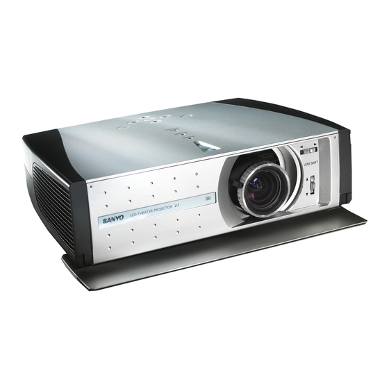
Page 9: Part Names And Functions
Part Names and Functions Front Back Bottom i o !0 !1 Exhaust Vent CAUTION Hot air is exhausted from the exhaust vent. Do not put heat-sensitive objects near this side. Air Intake Vent (The two arrows show air flow.) Top Controls and Indicators Front Cover Infrared Remote Receiver Projection Lens... -
Page 10: Terminal
Connect computer output (Digital/Analog DVI-I type), component video output, or RGB Scart 21-Pin video output to this terminal. (p16, 17) SERVICE PORT This jack is used to service this projector. VIDEO Connect the composite video output from video equipment to this jack. (p16) A built-in micro processor which controls this unit may occasionally malfunction and need to be reset. -
Page 11: Top
Turns the projector on or off. (p18) POWER indicator Flashes red until the projector gets ready to be turned on or when the front cover is closed. It lights red when the projector is in the stand-by mode. It remains green while the projector is under operation. -
Page 12: Remote Control
Displays the captured image. (p40) KEYSTONE button Corrects keystone distortion. (p20, 39) POWER ON-OFF button Turns the projector on or off. (p18) SELECT button Executes the item selected, or to expand or compress image in the Digital zoom mode. (p38) IMAGE ADJ. -
Page 13: Remote Control Operating Range
Remote Control Operating Range Point the remote control toward the projector (Infrared Remote Receiver) whenever pressing any button. Maximum operating range for the remote control is about 16.4’ (5m) and 60° in front of the projector. 16.4’ (5 m) Remote Control Batteries Installation Remove the battery compartment lid. -
Page 14: Installation
Positioning the Projector This projector is designed to project on a flat projection surface and can be focused from 3.9’(1.2m) - 20.0’(6.1m). Refer to the figure and the table below for the screen size and the distance between the projector and the screen. -
Page 15: Moving The Lens
Moving the Lens The projection lens can be moved up, down, left, and right with the manual lens shift function. This function makes it easy to provide a projected image where you want. Turn the lens shift ring (left/right) left/right to move the lens leftward / rightward. -
Page 16: Connecting To Video Equipment (Video, S-Video)
Use a DVI cable (option) for DVI compatible with HDCP. NOTE See page 55 for ordering optional cables. NOTE When connecting the cable, the power cords of both the projector and the external equipment should be disconnected from AC outlet. Video Equipment Composite S-VIDEO... -
Page 17: Connecting To Video Equipment (Rgb Scart)
Use a DVI-VGA cable (option) for analog. NOTE See page 55 for ordering optional cables. NOTE When connecting the cable, the power cords of both the projector and the external equipment should be disconnected from AC outlet. Installation Video Equipment RGB Scart... -
Page 18: Basic Operation
Do not use the projector for more than 24 hours continuously. Turn off the projector at least once in 24 hours and give it a rest. Continuous use may result in shortening the lamp lifetime. This projector monitors internal temperature and automatically controls the running speed of the cooling fans. -
Page 19: Zoom Adjustment
Zoom Adjustment Move the Zoom Lever to zoom in and out. Focus Adjustment Rotate the Focus Ring to adjust the projected picture focus. Aperture (Contrast) Adjustment Move the Aperture Lever to adjust contrast. Basic Operation Zoom Lever Focus Ring Aperture Lever... -
Page 20: Keystone Adjustment
Basic Operation Keystone Adjustment If a projected picture has keystone distortion, correct the image with KEYSTONE adjustment. Press the KEYSTONE L/M button on the remote control or select the Keystone in the Setting Menu (p39). The Keystone dialog box appears. Correct keystone distortion by pressing the KEYSTONE L/M button or the Point Up/Down button. -
Page 21: On-Screen Menu
On-Screen Menu You can control and adjust this projector through the On-Screen Menu. Refer to the following pages to operate each adjustment on the On-Screen Menu. Press the MENU button to display the On-Screen Menu (Main Menu). Select a menu from the main menu by pressing the Point Up/Down button, and press the Point Right button to enter the sub-menu. -
Page 22: Menus
Basic Operation Menus VIDEO MENUS Input Menu: selects video input source. (p23-25) AV System Menu: selects video system from AUTO, PAL, SECAM, NTSC, NTSC4.43, PAL-M, PAL-N, 1080i, 1035i, 720p, 575p, 480p, 575i, 480i. (p26) Image Select Menu: selects image level from Standard, Cinema, Game, and Image 1 ~ 4. (p27) Image Adjust Menu: adjusts Contrast, Brightness, Color, Tint, Color temp., White balance (R/G/B), Screen Menu: sets the screen size from Full, Full through, Zoom, Caption IN, Normal, Normal through, or Natural wide. -
Page 23: Video Input
Press the AUTO, VIDEO, S-VIDEO, or COMPO button on the remote control according to video input. It is convenient for you to select the AUTO as the projector automati- cally detects incoming video signal, and adjust itself to optimize its performance. - Page 24 Move the pointer to the source that you want to select and then press the SELECT button. Auto When selecting the AUTO button, the projector automati- cally detects incoming video signal, and adjusts itself to optimize its performance. However, the projector...
-
Page 25: Input Source Selection (Input 2 Terminal/Hdcp, Component, Scart)
Interface) from being copied. The specification of HDCP is decided and controlled by Digital Content Protection, LLC. Should the specification be changed, this projector may not display the digital content protected by HDCP. Component-DVI Cable and Scart-DVI Cable are options. See page 55 for order. -
Page 26: Video System Selection
When Video System is PAL-M or PAL-N, select system manually. PAL / SECAM / NTSC / NTSC4.43 / PAL-M / PAL-N If the projector cannot reproduce proper video image, it is necessary to select a specific broadcast signal format among PAL, SECAM, NTSC, NTSC 4.43, PAL-M, and PAL-N. -
Page 27: Image Level Selection
(Each time you press the PRESET IMAGE (P-IM) button, either Cinema or Game is selected.) Standard (STD) Normal picture level preset on this projector. Cinema [PRESET IMAGE (P-IM)] Picture level adjusted for the picture with fine tone. Game [PRESET IMAGE (P-IM)] Picture level suitable for playing a game. -
Page 28: Image Level Adjustment
Video Input Image Level Adjustment Select the Image Adjust Menu with the Point Up/Down button, and then press the Point Right button to enter the sub-menu. Select an item with the Point Up/Down button and press the Point Left/Right button to adjust the item. Contrast Press the Point Left button to decrease contrast and the Point Right button to increase contrast. - Page 29 Sharpness Press the Point Left button to soften the image and the Point Right button to sharpen the image. (From -7 to +7) Gamma Press the Point Left/Right button to obtain better balance of contrast. (From -7 to +7) Auto grayscale When this function is "ON", it automatically enhances contrast of bright and dark part of image.
-
Page 30: Screen Size Adjustment
Video Input Screen Size Adjustment This projector has a useful function to resize a projected screen. Select the Screen Menu with the Point Up/Down button, and then press the Point Right button to enter the sub-menu. Select an item with the Point Up/Down button and press the Point Left/Right button to set the screen size. -
Page 31: Computer Input
Computer Input Input Source Selection Direct Operation Choose INPUT 2 by pressing the INPUT button on the top control or on the remote control. Before using these buttons, correct input source should be selected through menu operation as described below. Menu Operation Select the Input Source Selection Menu with the Point Up/Down button, and then press the Point Right button to enter the sub-... -
Page 32: Computer System Selection
When selecting computer input, the projector automatically displays the most proper image for the input signal. One of the following four displays appears on the system menu icon. If the projector does not tune the input signal and the projected image is not displayed properly, or when you wish to adjust it manually, perform manual adjustment as described on page 34 and 35. -
Page 33: Computer Adjustment (Auto)
To store adjustment data Adjustment parameters from Auto PC Adjustment can be memorized in this projector. Once parameters are memorized, the setting can be done just by selecting Mode in the PC System Menu (p32). See “Store” on page 35. -
Page 34: Computer Adjustment (Manual)
Computer Input Computer Adjustment (Manual) Some computers employ special signal formats which may not be tuned by Multi-scan system of this projector. This projector has Manual PC Adjustment to enable you to precisely adjust several parameters to match those signal formats. - Page 35 Adjusts the horizontal area displayed by this projector. Press the Point Left/Right button to decrease/increase value and then press the SELECT button. Display area V Adjusts the vertical area displayed by this projector. Press the Point Left/Right button to decrease/increase value and then press the SELECT button. Full screen When this function is on, SXGA image is fully displayed at 4 : 3 aspect ratio.
-
Page 36: Image Level Selection
Image 3, and Image 4 by pressing the IMAGE buttons (STANDARD (STD), PRESET IMAGE (P-IM), and 1-4 buttons) on the remote control. Standard (STD) Normal picture level preset on this projector. Real [PRESET IMAGE (P-IM)] Picture level with improved halftone for graphics. -
Page 37: Image Level Adjustment
Image Level Adjustment Select the Image Adjust Menu with the Point Up/Down button, and then press the Point Right button to enter the sub-menu. Select an item with the Point Up/Down button and press the Point Left/Right button to adjust the item. Contrast Press the Point Left button to decrease contrast and the Point Right button to increase contrast. -
Page 38: Screen Size Adjustment
The True and Digital zoom cannot be selected when “480i”, “575i”, “480p”, or “575p” is selected in the PC System Menu (p32). This projector cannot display any resolution higher than 1280 X 720. If your computer’s screen resolution is higher than 1280 X 720, reset the resolution to the lower before connecting to the projector. -
Page 39: Setting
Correct keystone distortion by pressing the Point Up/Down button. Refer to Keystone Adjustment on page 20. Blue back When this function is “On,” the projector produces a blue image while input signal is not detected. Display This function decides whether to display On-Screen Displays. - Page 40 Logo function and set it as “User”. Then the captured image will be displayed when turning on the projector next time or pressing the MY PICTURE (MY-P) button on the remote control. (p12) To capture the image, select [Yes]. To cancel the Capture function, select [No].
- Page 41 ···· lowers brightness and reduces the lamp power consumption. Remote control This projector has two different remote control codes: Code 1 (initial code) and Code 2. This switching function prevents remote control interference when operating several projectors or video equipment together.
-
Page 42: Maintenance And Cleaning
Maintenance and Cleaning Warning Indicator The WARNING indicator shows the state of the function which protects the projector. Check the state of the WARNING indicator and the POWER indicator to take proper maintenance. The projector is shut down and the WARNING indicator is flashing red... -
Page 43: Cleaning The Air Filter
Cleaning the Air Filter The air filter prevents dust from accumulating on the surface of the optical elements inside the projector. Should the air filter become clogged with dust particles, it will reduce cooling fans’ effectiveness and may result in internal heat build up and adversely affect the life of the projector. -
Page 44: Cleaning The Projection Lens
Avoid using an excessive amount of cleaner. Abrasive cleaners, solvents, or other harsh chemicals might scratch the surface. When the projector is not in use, put the projector in the carry- ing case to protect it from dust and scratches. -
Page 45: Lamp Replacement
Lamp Replacement When the life of the projection lamp of this projector draws to an end, the LAMP REPLACE indicator lights yellow. If this indicator lights yellow, replace the lamp with a new one promptly. CAUTION Allow a projector to cool, for at least 45 minutes before you open the Lamp cover. -
Page 46: Lamp Replace Counter
Additionally, check carefully to ensure that there are no broken shards or pieces of glass around the projector or coming out from the cooling air circulation holes. Any broken shards found should be cleaned up carefully. No one should check the inside of the projector except those who are authorized trained technicians and who are familiar with projector service. -
Page 47: Appendix
Equipment” and "Connecting to a Computer" on page16 and 17. – Make sure all equipment is connected to AC outlet and the power is turned on. – When you operate the projector with a computer and it does not project an image, restart the computer. – Try these solutions. - Page 48 High voltages are used to operate this projector. Do not attempt to open the cabinet. If problems still persist after following all operating instructions, contact the dealer where you purchased the projector or the service center. Give the model number and explain about the problem. We will advise you how to obtain service.
-
Page 49: Indicators And Projector Condition
The projector detects an abnormal condition and cannot be turned on. Unplug the AC power cord and plug it again to turn on the projector. If the projector is turned off again, disconnect the AC power cord and contact the dealer or the service center for service and checkup. -
Page 50: Menu Tree
Appendix Menu Tree Video Input/Computer Input Input Input 1 Input 2 Video Input System Auto SECAM NTSC NTSC 4.43 PAL-M PAL-N System Auto 1080i 1035i 720p 575p 480p 575i 480i Image Select Auto Video S-Video Y, Pb/Pc, Pr/Cr RGB( Analog ) RGB( PC Digital ) RGB( AV HDCP ) Component... - Page 51 Computer Input System Mode 1 Mode 2 SVGA 1 - - - - ✽Systems displayed in the System Menu vary depending on an input signal. PC Adjust Auto PC Adj. Fine sync. Total dots Horizontal Vertical Current mode Clamp Display area Display area - H Display area - V Full screen...
-
Page 52: Compatible Computer Specifications
Appendix Compatible Computer Specifications Basically this projector can accept the signal from all computers with the V, H-Frequency below mentioned and less than 100 MHz of Dot Clock. ON-SCREEN RESOLUTION DISPLAY VGA 1 640 x 480 VGA 2 720 x 400... -
Page 53: Technical Specifications
Technical Specifications Projector Type Dimensions (W x H x D) Net Weight LCD Panel System Panel Resolution Number of Pixels Color System High Definition TV Signal Scanning Frequency Projection Image size (Diagonal) Projection Lens Throw Distance Projection Lamp Video Input Jacks... -
Page 54: Dimensions
Appendix Dimensions Unit : inch (mm) 4.52 (114.7) 14.13 (359) 11.8˚ (Max.) ON-OFF POWER WARNING 10.79 (274) LAMP REPLACE MENU INPUT SELECT 3.82 (97) -
Page 55: Configurations Of Terminal
Configurations of Terminal DVI-I RGB/COMPONENT TERMINAL (DIGITAL/ANALOG) Terminal : DVI-I Pin Configuration C1 C2 Optional Parts The parts listed below are optionally supplied. When ordering those parts, give the name and Type No. to the sales dealer. G Wall Anchor Kit G DVI Cable G DVI-VGA Cable G Component Cable (32.8’/10m) - Page 56 Printed in Japan Part No. 610 309 7923 (1AA6P1P4276-- M4KA) SANYO Electric Co., Ltd.