Table of Contents
Advertisement
Quick Links
ALINCO,INC.
Head Office: Yodoyabashi-Dai Building 13th Floor
4-9, 4-Chome, Koraibashi, Chuo-ku, Osaka 541-0043, Japan
Phone: +81-6-7636-2362 Fax: +81-6-6208-3802
http://www.alinco.com/
E-mail: export@alinco.co.jp
Printed in Japan
Copyright Alinco, Inc. PS0610
FNNM-EN
ALL MODE HF TRANSCEIVER
DX-SR8
Instruction Manual
Thank you for purchasing your new ALINCO transceiver.
This instruction manual (and addendum sheets) contains important safety and operating instructions.
Please read this manual carefully before using the product and keep it for future reference.
Advertisement
Table of Contents

Related Manuals for Alinco DX-SR8


Summary of Contents for Alinco DX-SR8
-
Page 1: Instruction Manual
Phone: +81-6-7636-2362 Fax: +81-6-6208-3802 http://www.alinco.com/ E-mail: export@alinco.co.jp Thank you for purchasing your new ALINCO transceiver. This instruction manual (and addendum sheets) contains important safety and operating instructions. Please read this manual carefully before using the product and keep it for future reference. - Page 2 The FCC Part 15 approval is not required for amateur-radio use of this device in USA/Canada. Copyright © All rights reserved. No part of this document may be reproduced, translated or transcribed in any form or by any means without the prior permission of Alinco. Inc., Osaka, Japan, English Edition Printed in Japan.
-
Page 3: Table Of Contents
Limited Power Source................9 Introduction ..................10 Chapter 1 Getting Started ............11 1.1 Features ......................11 DX-SR8 Features ..................11 1.2 Standard Accessories ..................12 Checking Accessories ................12 1.3 Installation and Connection (For Base Station) ..........13 Connection Diagram ................13 Procedure .................... - Page 4 Contents Procedure ....................35 2.4 Practical Techniques for SSB Operation ............36 Introduction....................36 Eliminating Interference (QRM) ............... 36 Communicating in Bad Conditions ............37 Communicating with Off-frequency Stations ........... 37 Communicating in Pile-ups ..............37 2.5 AM Operation ....................38 Procedure ....................
- Page 5 Contents Chapter 4 Scanning ..............55 4.1 Basics ......................55 Introduction....................55 Scan Types ....................55 Scanning conditions ................57 4.2 Band Scan ...................... 58 4.3 Programmed Scan ..................59 4.4 Search Scan ....................59 4.5 Memory Scan ....................60 4.6 Skip-channel Setting ..................60 4.7 Priority Scan ....................
- Page 6 7.3 Reset ......................87 Procedure ....................87 7.4 Cleaning ......................87 7.5 Troubleshooting ....................88 Appendix ..................90 Options ......................... 90 About Mounting Bracket and Carrying Handle ............. 91 External Antenna Tuner (Optional) ............... 92 ALINCO EDX-2 ..................92 Specifi cations ....................... 93...
-
Page 7: Warning
WARNING To prevent any hazard during operation of Alinco’s radio product, in this manual and on the product you may fi nd symbols shown below. Please read and understand the meanings of these symbols before starting to use the product. -
Page 8: Handling This Product
WARNING Risk of explosion if battery is replaced with an incorrect type. Dispose of, or recycle used batteries according to your local regulations. The manufacturer declines any responsibilities against loss of life and property due to a failure of this product when used with or as a part of a device made by third parties. Use of third party accessory may result in damage to this product. -
Page 9: In Case Of Emergency
WARNING In case of emergency: In case of the following situation(s), please turn off the product, switch off the source of power, then remove or unplug the power-cord. Please contact your local dealer of this product for service and assistance. Do not use the product until the trouble is resolved. Do not try to troubleshoot the problem by yourself. -
Page 10: About Transceiver
WARNING About transceiver Do not connect devices other than specifi ed ones to the jacks and ports on the product. It may result in damage to the devices. Turn off and remove the power-source (AC cable, DC cable, battery, cigar-cable, charger adapter etc) from the product when the product is not in use for extended period of time or in case of maintenance. -
Page 11: Before Operating The Transceiver
fi re within the device if the fi re starts under certain fault conditions. Alinco will not take responsibility for any fi re hazard associated with powering the transceiver or charging its batteries using a power source that does not belong to the limited power source in... -
Page 12: Introduction
Introduction Thank you very much for purchasing this excellent Alinco transceiver. Our products are ranked among the fi nest in the world. This radio has been manufactured with state of the art technology and it has been tested carefully at our factory. It is designed to operate to your satisfaction for many years under normal use. -
Page 13: Chapter 1 Getting Started
Each stores mode, fi lter, split frequencies, AGC, attenuator (or pre-amp), noise-blanker settings and more. Computer control The DX-SR8 can be controlled by a personal computer through the serial interface. Settings of frequency, mode, power, and memory channel can be controlled. (Optional PC interface cable required) -
Page 14: Standard Accessories
Manual The standard accessories may vary slightly depending on the version you have purchased. Please contact your local authorized Alinco dealer should you have any questions. ALINCO and authorized dealers are not responsible for any typographical errors there may be in this manual. Standard accessories may change without notice. -
Page 15: Installation And Connection (For Base Station)
Chapter 1 Getting Started 1.3 Installation and Connection (For Base Station) Connection Diagram This diagram shows the connections for a base station. 13.8V DC regulated power supply HF band antenna Microphone Stand EDX-2 (optional) Headphone Speaker Long-wire antenna optional Procedure 1. - Page 16 30A or more. Power supplies that do not meet those specifi cations may cause malfunction and/or damage to the radio and will void the warranty. Alinco offers excellent communication-grade power supplies as optional accessories. Please contact your local authorized Alinco dealer.
- Page 17 Chapter 1 Getting Started 6. Installing the control panel and body separately IMPORTANT: Be sure to disconnect the power cable before carrying out this procedure. Remove 2 screws above the main unit to separate the front-control panel. Disconnect the cable Remove other 2 screws at the bottom of the main unit.
-
Page 18: Installation And Connection (For Mobile Operation)
Chapter 1 Getting Started 1.4 Installation and Connection (For Mobile Operation) Connection Diagram This diagram shows the connections for mobile operation. DX-SR8 Co-ax Control cable Grounded Mobile whip antenna Grounded Mobile-base Single wire (Not Co-ax cable) Automatic antenna tuner EDX-2 (Options;... - Page 19 Chapter 1 Getting Started 2. Connecting the power cable IMPORTANT: Use a 12 V car battery to operate the transceiver. Connect the supplied power cable directly to Chassis the car battery. To engine room To passanger cabin Black Transceiver Fuse Chassis NOTE: If threading the cable through wiring...
-
Page 20: Controls, Connectors, And Display
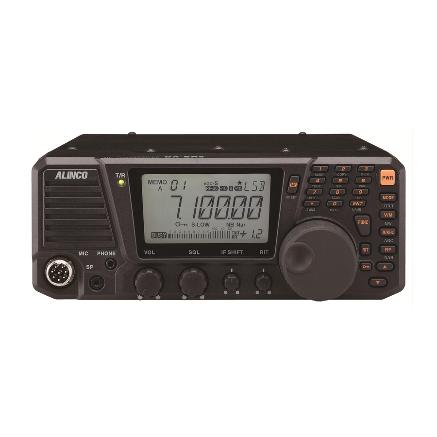
Chapter 1 Getting Started 1.5 Controls, Connectors, and Display Front Panel (22) (23) (12) (11) (21) (10) (20) (19) (18) (17) (16) (15) (14) (13) No. Key Principal Function (1) POWER SWITCH Turns the power on/off. [PWR] (2) [MODE] key Press to select the USB, LSB, CWU, CWL, AM, or FM modes. -
Page 21: Front Panel (Keypad)
Chapter 1 Getting Started No. Key Principal Function (18) PHONE jack [PHONE] For connecting external headphones. Takes 8 to 32 ohm impedance headphones. (19) SPEAKER jack [SP] For connecting an external speaker. Takes 8 to 16 ohm impedance speakers. Connect optional ERW-4C or ERW-7 cable for PC-interface. (20) Microphone connector For connecting a microphone. - Page 22 Chapter 1 Getting Started Connecting the Microphone Plug the microphone into the microphone connector on the body. Tighten the screw on the connector to secure the connection. Microphone Headphone Speaker NOTE: Please be sure that the connector is securely tightened, and check the connection from time to time.
-
Page 23: Rear Panel
Chapter 1 Getting Started Rear Panel No. Key Function (1) ANTENNA connector For connecting an HF band antenna. Takes a 50 ohm impedance coaxial cable with PL-259 connector. (2) RELAY (external relay) For connecting external equipment such as a linear amplifi er for jack switching between reception and transmission. -
Page 24: Microphone
Chapter 1 Getting Started Microphone (5); EMS-53 (5); EMS-64 No. Key Function (1) UP Increase the frequency, memory channel number, or setting channel. (2) DOWN Decrease the frequency, memory channel number, or setting channel. (3) PTT Press the [PTT (Push-To-Talk)] key to transmit. (4) Lock Switch Locks out the [UP] and [DOWN] keys. -
Page 25: Display
Chapter 1 Getting Started Display (10) (14) (12) (16) (11) (15) (13) (17) (18) (19) No. Key Function Appears in the MEMORY mode, indicating the selected memory channel. Indicates the selected VFO mode A or B. Appears while the external automatic antenna tuner is being tuned. - Page 26 Chapter 1 Getting Started Quick Reference of Control keys There are 3 types of key operations; simply press it, press it after [FUNC] key, or press and hold it for more than 1 second (*). NOTE: FUNC + this key: Press [FUNC] key, then press this key. (P.xx) refers to the page this operation is mentioned in this manual.
-
Page 27: Chapter 2 Communications
Chapter 2 Communications 2.1 Reception Basics Introduction Reception is a basic transceiver operation. In this section, you can familiarize yourself with the operation of controls used for reception. Procedure 1. Turning the unit power on and off. NOTE: Make sure that all antenna and power connections are correct before turning the power By pressing the [PWR] key the power turns on. - Page 28 • DX-SR8 remembers the last used mode. 5. Selecting amateur radio bands Amateur radio bands are frequency bands that hams are allowed to use. DX-SR8 covers all amateur radio bands ranging from 1.8 MHz to 29 MHz. Press the [M/KHz] key repeatedly until the cursor fl...
- Page 29 Chapter 2 Communications Each time the [M/KHz] key is pressed, shifts in the following manner: fl ashing above MHz frequency indication. Changes the BAND. above MHz frequency indication. Changes the 1 MHz digit. fl ashing above 1 kHz frequency indication. Changes the 100 kHz digit.
- Page 30 Press the [FUNC] key, then press the [1] key will switch between the VFO A and VFO B. Select either VFO. NOTE: DX-SR8 has the VFO and MEMORY modes (see page 51). In the VFO mode, different frequencies and settings can be set in each individual VFO A and VFO B. Using the main tuning dial •...
-
Page 31: Exercise
Chapter 2 Communications Exercise • Try receiving a 28.200 MHz signal in the AM mode. Make sure that antenna connection is correct. Turn the power on. Rotate the VOL knob to adjust the audio level. NOTE: Be sure that the SQL knob is fully turned to the left to unmute the squelch. -
Page 32: Direct Frequency Entry With Keypad
Chapter 2 Communications Direct Frequency Entry with Keypad The transceiver has a keypad for direct frequency entry as described below. Press the [ENT] key, then press the numeral keys on the keypad to enter the MHz digits for the desired frequency. If a key is mistakenly pressed, press any key except keypad and start again from the beginning. -
Page 33: Getting Familiar With Useful Functions
Chapter 2 Communications Getting Familiar with Useful Functions In HF band, receive conditions vary not only with bands and modes but with time and season. To obtain optimum signal reception, get familiar with and take full advantage of these versatile funcitons. - Page 34 Chapter 2 Communications RIT (Receiver Incremental Tuning) Press the [RIT] key. The “RIT” icon will appear on the LCD. Rotate the RIT control knob to adjust the frequency. * To exit from the RIT function, press the [RIT] key repeatedly until both “RIT/TXIT” icons disappear.
-
Page 35: Transmission Basics
Chapter 2 Communications 2.2 Transmission Basics Introduction This section explains the preparations and basic procedures for transmission. Procedure Transmitting in the voice mode (SSB, AM and FM) Make sure that all antenna, power, and microphone connections are correct. Turn the power on. Using the normal reception procedure, select a clear frequency free of other stations or select the frequency of a station to communicate with. - Page 36 Chapter 2 Communications Selecting output power level To select the output power, press [FUNC] key and then press [0] key while “FUNC” icon is on the display. As the [0] key is pressed, the output power changes among 3 levels. The “S-LOW”...
-
Page 37: Ssb Operation
Chapter 2 Communications 2.3 SSB Operation Introduction The SSB (Single Side Band) mode is most frequently used for voice communication in HF bands. Procedure NOTE: Make sure that all antenna, power, and microphone connections are correct. Trun the power on. Select the desired amateur radio band (see page 27). -
Page 38: Practical Techniques For Ssb Operation
Chapter 2 Communications Press and hold the [PTT] key and speak into the microphone. The red TX LED will be lit. The reading on the RF meter and brightness of the TX LED will change according to the intensity of your voice. -
Page 39: Communicating In Bad Conditions
Chapter 2 Communications Communicating in Bad Conditions In HF band, propagations depend on time, season, and propagation paths. For example, signals from the other station may fade or alternate between strong and weak. In this case, perform the following. 1: Using the RF preamplifi er Press the [RF] key repeatedly until [+10] appears. -
Page 40: Am Operation
Chapter 2 Communications 2.5 AM Operation Procedure NOTE: Make sure that all antenna, power, and microphone connections are correct. Turn the power on. Select the desired operating band (see page 27). Press the [MODE] key to select the AM mode. Tune in a station to communicate with. -
Page 41: General Coverage Receiver Operation
Chapter 2 Communications 2.6 General Coverage Receiver Operation Introducution This section explains procedures for receiving MW and SW broadcasts using the general coverage receiver function. Procedure Example: Receiving a 670 kHz (0.670 MHz) MW broadcasts Make sure that all antenna and power connections are correct. - Page 42 Chapter 2 Communications Press the [ ] key until 0 appears on 1MHz digit indication. Press the [MODE] key to select the AM mode. NOTE: You may operate [M/KHz] key to select MHz digit as you like fi rst, but depending on the frequency combination in relation to the band- plan programming, zero on the MHz order may not be shown.
-
Page 43: Fm Operation
Select the desired operating band (see page 27). NOTE: In the FM mode, DX-SR8 is designed to use the super narrow (±2.5 kHz deviation). Press the [MODE] key to select the FM mode. -
Page 44: Repeater Operation (Quick Offset)
Chapter 2 Communications 2.8 Repeater Operation (QUICK OFFSET) Introduction This section explains procedures of how to access to a repeater. The function explained in this section is referred to as a “QUICK OFFSET”. Procedure Example: Selecting 29.640 MHz for reception and 29.540 MHz for transmission Make sure that all antenna, power, and microphone connections are correct. -
Page 45: Cw Operation
Start keying. NOTE: DX-SR8 has the FULL BREAK-IN and SEMI BREAK-IN modes. For the SEMI BREAK-IN mode, you can select one of eight levels including the AUTO mode, in which the delay time is set automatically. -
Page 46: Practical Techniques For Cw Operation
Chapter 2 Communications 2.10 Practical Techniques for CW Operation Introduction In CW operation, you will encounter various problems such as poor propagations and interferences. This section explains how to use the special functions to overcome these problems. Reducing Interference 1: Activating IF SHIFT function This function eliminates interference by shifting the fi... -
Page 47: Split-Frequency Operation
Chapter 2 Communications 2.11 Split-Frequency Operation Introduction When communicating with a DX (long distance) station that is using a different operating band or is involved in a pile-up, they may be using one VFO for the receive frequency, and the other VFO for the transmit frequency. -
Page 48: Rtty Packet Operation (Fax/Sstv)
Chapter 2 Communications 2.12 RTTY Packet Operation (FAX/SSTV) Introduction DX-SR8 has no dedicated features for RTTY packet, FAX, and SSTV operations. However, these operations can be enabled by using the following procedures. Audio frequency IN (Microphone Connector) Audio frequency OUT Connecting Additional Equipment Pin (1) —... -
Page 49: Chapter 3 Memory Features
Chapter 3 Memory Features 3.1 Basics This transceiver has three memory banks. 200 memory channels are available in each bank, for a total of 600 channels. Each can retain different operating data such as receive and transmit frequencies mode, tone etc. It is useful to store regularly used frequencies in the memory and operate in the memory mode. -
Page 50: Simplex-Vfo-Frequency Programming
Chapter 3 Memory Features 3.2 Simplex-VFO-Frequency Programming Procedure Example: Storing 7.050.00 MHz and LSB into memory channel “188” in bank A. Please note that a symbol stands for “blank” bank and nothing appears on the display. Setting data Set the data to be stored in VFO made. Selecting a memory channel Press the [FUNC] key. -
Page 51: Split-Frequency Programming Using Quick Offset Function
Chapter 3 Memory Features 3.3 Split-Frequency Programming Using Quick Offset Function Procedure Example: Programming 14.275.00 MHz (transmit frequency) and 14.250.0 MHz (receive frequency) into memory channel “59” Setting data Set 14.250 MHz (receive frequency) in either VFO A or VFO B. Press the [FUNC] key, then press [5] key. -
Page 52: Split-Frequency Programming
Chapter 3 Memory Features 3.4 Split-frequency Programming Procedure Example: Programming 29.540.00 MHz (transmit frequency) and 29.640.00 MHz (receive frequency) into memory channel “03” Setting data Set 29.540.00 MHz (transmit frequency) in the VFO A. • Select FM mode by [MODE] key. Press [FUNC] then [4] key to activate CTCSS tone encoding. -
Page 53: Memory Mode Operation
Chapter 3 Memory Features 3.5 Memory Mode Operation Procedure Accessing the Memory Mode Press the [V/M] key to display the channel number and MEMO. The last-used memory channel will be recalled. NOTE: Memory channel will not appear if nothing has been programmed in the memory. -
Page 54: Memory Channel Data Erasing
Chapter 3 Memory Features 3.6 Memory Channel Data Erasing Erasing Data in a Selected Memory Channel Press the [V/M] key to access the Memory mode. Press the [ / ] keys or press [UP/DOWN] key of microphone to select a memory channel that you want to erase. -
Page 55: Memory To Vfo Data Transfer
Chapter 3 Memory Features 3.7 Memory To VFO Data Transfer Introduction This function copies data from any memory channel to the VFO. This is useful when you wish to tune in a station near the frequency stored in a memory channel. Procedure Example: Copying data in memory channel “06”... - Page 56 Chapter 3 Memory Features Enter the next character with the [ENT] key. (Repeat the same sequence) In order to store 6 letters for example, repeat the sequence until all 6 letters are entered by [ENT] key, and only 7th digit is fl ashing. To enter 7 letters, repeat until 1st digit fl...
-
Page 57: Chapter 4 Scanning
Chapter 4 Scanning 4.1 Basics Introduction Scanning lets you automatically search for signals across a specifi c frequency range or among programmed memory channels. There are fi ve types of scans; band, programmed, search, memory, and priority. Basically the squelch must be closed (muted) to run the scans. However, the following scan modes work regardless of the squelch level. - Page 58 Chapter 4 Scanning Programmed Scan This function scans an user-specifi ed range of frequencies. Before using this function, you need to specify the upper and lower frequency limits for programmed-scanning. These frequencies are called “Programmed scan channels”, and are available a pair in VFO A and VFO B separately.
-
Page 59: Scanning Conditions
Chapter 4 Scanning Priority Scan • The transceiver receives signals on a VFO or a memory channel for 5 seconds, and then scans a memory or a VFO you specifi ed for 0.5 seconds (2 seconds if squelch is unmuted). Display frequency Priority frequency (5 seconds) -
Page 60: Band Scan
Chapter 4 Scanning 4.2 Band Scan By setting the Band scan in the Set mode Menu 04 (Page 74): Enter to either the VFO A or B in the VFO mode. Press the [FUNC] key, then press the [8] key to start scanning. -
Page 61: Programmed Scan
Chapter 4 Scanning 4.3 Programmed Scan By setting the Programmed scan in the Set mode Menu 04: Enter to the VFO A or B in the VFO mode. Be sure that the P1/P2 channels are correctly programmed in the memory channels prior to use this scan mode. -
Page 62: Memory Scan
Chapter 4 Scanning 4.5 Memory Scan To scan the memory channels stored in the selected memory bank: Enter to either one of the memory banks. The memory indication appears like an example on upper left corner of the display. Press the [FUNC] key, then press the [8] key This is an example. -
Page 63: Priority Scan
Chapter 4 Scanning 4.7 Priority Scan You can monitor 2 frequencies every 5/0.5 seconds alternatively. Any combination of VFO and / or memory channel frequency can be coupled for priority monitoring. Stay tuned to the main frequency you wish to monitor for 5seconds, and select the priority frequency (or channel) to monitor 0.5 seconds (and stay there for 2 seconds if a signal is picked up). -
Page 64: Chapter 5 Special Functions
Chapter 5 Special Functions 5.1 Interference Reducers Introduction As explained in previous chapters, this transceiver has built-in functions to reduce interferences. This section explains how to use these functions to reduce interference in detail, although you may be already familiar with these features. IF SHIFT The IF SHIFT function is used to shift the IF pass band without changing the receive frequency. -
Page 65: Narrow Filter
Chapter 5 Special Functions Narrow Filter The narrow fi lter can be used in AM, SSB and CW mode. This allows you to effectively reduce interference. Standard filter Narrow filter • If there are interference signals (A) and (B) when the standard fi lter is used, using the narrow fi... -
Page 66: Cw Bfo Reverse
Chapter 5 Special Functions CW BFO REVERSE The CW mode has CWU (upper sideband) and CWL fBFO (lower sideband) options. Selecting the CWU or CWL can help reduce interference. When your receive frequency is zeroed-in with the other station's transmit frequency, this function would not affect the receive tone or transmit frequency. -
Page 67: Other Useful Functions
Chapter 5 Special Functions 5.2 Other Useful Functions RIT/TXIT Function RIT/TXIT Function Once the communication is established, instead of using the main dial, RIT and TXIT are used to fi ne-tune the operating frequencies during the communication. RIT is the feature to vary your receiving frequency only without changing the transmitting frequency, TXIT is vice versa. -
Page 68: F (Plus-Minus Delta F) Function
Chapter 5 Special Functions ± f (Plus-Minus Delta F) Function This feature adds current RIT/TXIT values to the original operating frequency and exits from the RIT/TXIT function. This is useful when your communication frequency is established and RIT/TXIT is no longer necessary. Procedure While operating RIT/TXIT, press [FUNC] key. -
Page 69: Multi Function Feature
Chapter 5 Special Functions MULTI FUNCTION Feature Any key operation can be assigned to the [MF] key as a short-cut. * All key functions and Set mode parameters can be assigned to this feature except [PTT] key operation. Example: Assign the scan speed setting in the Set mode to the [MF] key. Press the [FUNC] key, then press the [MF] key. -
Page 70: Dial Lock Function
Chapter 5 Special Functions DIAL LOCK Function This function locks the main tuning dial to prevent accidental frequency changes. NOTE: This function is useful in mobile operation where the main tuning dial may be rotated by car vibrations, etc. While this function is activated, tuning is still possible with the [ / ] keys and RIT control knob. -
Page 71: Cable Clone
Chapter 5 Special Functions CABLE CLONE This feature will copy the programmed data and parameters in the master unit to slave units. It copies the parameters and memory program settings. Plug configuration (both for Master/Slave) DATA TX/RX 3.5 mm stereo-mini plug Master side Slave side Connection... -
Page 72: Chapter 6 Parameter Setting Mode (Set Mode)
Chapter 6 Parameter Setting Mode (Set mode) IMPORTANT: Please read the following pages thoroughly prior to the change of any parameters. THE PARAMETERS CANNOT BE SET WITHOUT ENTERING THE SET MODE. By entering the Parameter Setting mode, some of the radio’s operating parameters can be changed to suit your preferences. -
Page 73: Menu 00. Frequency Step Of The [ / ] Keys Setting
Chapter 6 Parameter Setting Mode (Set mode) Press [ / ] or [UP/DOWN] keys again to set the selected parameter and move to the next programming. Press any key other than [ / ] or [UP/DOWN] keys to set the selected parameter and exit from the Parameter setting mode. -
Page 74: Fm Mode
Chapter 6 Parameter Setting Mode (Set mode) • FM Mode While the unit is in FM mode, enter into the Set mode and select menu 00. The current frequency step will be displayed. You can change the frequency step as below by rotating the main dial. -
Page 75: Menu 02. Memory Frequency Access Protection
Chapter 6 Parameter Setting Mode (Set mode) Menu 02. Memory Frequency Access Protection Memory frequencies can be temporary changed by using main dial etc. during the operation. However, by selecting ACCS-OF here, the memory frequency can’t be changed except by using RIT/TXIT. -
Page 76: Menu 04. Select Scan Types
Chapter 6 Parameter Setting Mode (Set mode) B10S: The scan stops regardless of a signal by all means, and will resume scanning after 10 seconds. B20S: The scan stops regardless of a signal by all means, and will resume scanning after 20 seconds. B30S: The scan stops regardless of a signal by all means, and will resume scanning after 30 seconds. -
Page 77: Menu 05. Search Range Setting For Search Scan
Chapter 6 Parameter Setting Mode (Set mode) Menu 05. Search range setting for Search scan This is to set the scanning range applied to Search scanning. 50, 100 and 200 kHz are available as parameters. Default range is [SSC-50]. Rotate the main dial to select the scanning range. -
Page 78: Menu 07. Dimmer
Chapter 6 Parameter Setting Mode (Set mode) Menu 07. Dimmer The LCD illumination dimmer is available to adjust the luminosity of the display as you prefer. The [DIMR-32] appears on the display. (Default) By rotating the main dial, the display changes as shown and the luminosity changes. -
Page 79: Menu 09. Automatic Usb/Lsb Selection
Chapter 6 Parameter Setting Mode (Set mode) Menu 09. Automatic USB/LSB Selection This function automatically selects the USB or LSB mode depending on which amateur radio band has been selected in SSB mode. If “OFF” in selected, the last-used SSB mode is recalled regardless of the band. -
Page 80: Menu 11. Txit Function Setting
Chapter 6 Parameter Setting Mode (Set mode) Menu 11. TXIT Function Setting This is to allow/prohibit the access to TXIT. If “OF”(OFF) in selected, only an RIT function works. The [TXIT-ON] appears on the display. (Default) Turn the main dial counterclockwise, the display changes into the [TXIT-OF] and only an RIT function works. -
Page 81: Menu 14. Electronic Keyer Reverse Setting
Chapter 6 Parameter Setting Mode (Set mode) Menu 14. Electronic Keyer Reverse Setting When Electronic Keyer setting is ON (Refer to menu 12), you can change the dots and the dash keying positions (left and right strokes). Default is [PADDL-N] and operates in normal position. -
Page 82: At (Auto)
Chapter 6 Parameter Setting Mode (Set mode) • AT (AUTO) The delay time for the SEMI BREAK-IN mode will be set automatically according to the code speed being transmitted. • 1 to 7 Select the desired delay time for the SEMI BREAK-IN mode (“1” is the shortest, and ‘’7” is the longest). -
Page 83: Menu 18. Ctcss Tone Encoding Setting
Chapter 6 Parameter Setting Mode (Set mode) Menu 18. CTCSS Tone Encoding Setting The CTCSS tone, sometimes called PL tone, is a sub-audible tone superimposed on your voice. It is used for repeater uplink on 29 MHz FM band. There are 39 types of tones. The tone setting is activated only in FM mode. -
Page 84: Menu 20. Ptt Key Lock
Chapter 6 Parameter Setting Mode (Set mode) Menu 20. PTT Key Lock This is to deactivate the PTT key. Default is [PTT.L-OF]. Turn the main dial clockwise, select [PTT. L-ON] to use DX-SR8 as a receiver. counterclockwise clockwise PTT.L-OF PTT.L-ON Menu 21. -
Page 85: Menu 22. Up/Down Keys Function Setting
Chapter 6 Parameter Setting Mode (Set mode) MENU 22. UP/DOWN keys function setting Function for pressing [ / ] and UP/DOWN keys on the microphone can be set to starting scanning or a key-repeat to increase/decrease values continuously (and faster) while holding down the key. -
Page 86: Chapter 7 Maintenance
7.1 Adjustment Introduction DX-SR8 has been strictly tested and completely adjusted at the factory prior to shipment. When adjusting, therefore, be careful not to touch the non-user-servisable components such as the preset resistors/pots, and trimmers inside. Off-alignments caused by an user voids warranty. -
Page 87: Procedure
The adjustments are strictly at users' risks and any damage to the unit due to failure of adjustments void the warranty. If you are not familiar with the radio maintenance, please consult your local Alinco dealer for technical assistance. S-Low setting requires a power- meter. Use only ceramic driver to deal with the potentiometers. -
Page 88: Fuse Replacement
30 A CIRCUITRY FUSE REPLACEMENT The 13.8V DC from the power cable is applied to all circuits in the DX-SR8 through the circuitry fuse. This fuse is installed in the PA unit. Remove the top cover as shown on P.84. -
Page 89: Reset
• It is recommended to use reset features whenever you get lost with the explanation of this manual until you get familiar with the functions of DX-SR8. All LCD segments 7.4 Cleaning... -
Page 90: Troubleshooting
Chapter 7 Maintenance 7.5 Troubleshooting If a problem should occur, fi rst try the troubleshooting procedure given below. If the problem persists, contact your nearest ALINCO dealer for technical assistances. Symptom Possible Cause Remedy Power does not 1. DC power cable is incorrectly 1. - Page 91 * Reduce output power. A fi rmware update may be available from our web site at alinco.com, and it may alter the function of the product after the update is performed. Please refer to the information given on the same site for details. It is recommended that you tell the version of fi...
-
Page 92: Appendix
Appendix Options Following accessories are available at your ALINCO dealer. • EDX-2 automatic Long-wire antenna tuner [Not RoHS compliant] • EDS-17 Front control remote kit (Comes with 5 m Cable, front-panel bracket, unit-cover and hardwares) • Regulated DC power supply •... -
Page 93: About Mounting Bracket And Carrying Handle
Appendix About Mounting Bracket and Carrying Handle CAUTION: Use only specifi ed screws otherwise may cause damages to the components inside and voids warranty. Screw holes for mounting bracket Use a third-party mounting bracket for mobile operation. recommended recommended screw M5 × 6 screw M4 ×... -
Page 94: External Antenna Tuner (Optional)
Appendix External Antenna Tuner (Optional) ALINCO EDX-2 • Connection Example Radiating element DX-SR8 EDX-2 Coax Cable * Although EDX-2 has been designed to be water-proof, it is strongly suggested to shelter from rain and/or direct sunlight. Radiating element (antenna wire) -
Page 95: Specifi Cations
Appendix Specifi cations General DX-SR8 ALL MODELS Operating mode J3E (USB, LSB), A3E (AM), A1A (CW), F3E (FM) Number of memory channels 600 channels simplex Antenna impedance unbalanced Frequency stability ± 1ppm Power requirement 13.8 V DC ±15 % (11.7 to 15.8 V) - Page 96 Appendix DX-SR8T DX-SR8E Microphone impedance Transmit Frequency 160m band (1.8 M) 1.80000 - 1.99999 MHz 1.80000 - 1.99999 MHz coverage 80m band (3.5 M) 3.50000 - 3.99999 MHz 3.40000 - 3.99999 MHz * 60m band (5.3 M) 5.33050 MHz 5.34650 MHz 5.36650 MHz 5.37150 MHz 5.40350 MHz...
- Page 97 Appendix Quick references of keys and parameters Quick Reference of control keys setting mode. * You may make copies of this page, cut M→V M Erase BANK (1.9M) (3.5M) (5.3M) the charts and carry them with the unit for MF SET your references.
Need help?
Do you have a question about the DX-SR8 and is the answer not in the manual?
Questions and answers