Table of Contents
Advertisement
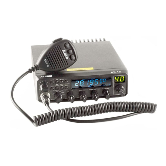
DX-10
Thank you for purchasing your new Alinco transceiver.
Please read this manual carefully before using the product
to ensure full performance, and keep this manual for future
reference as it contains information on after-sales services. In
case addendum or errata sheets are included with this product,
please read those materials and keep them together with this
Instruction Manual
instruction manual for future reference.
Advertisement
Table of Contents
Troubleshooting

Related Manuals for Alinco DX-10


Summary of Contents for Alinco DX-10
- Page 1 DX-10 Thank you for purchasing your new Alinco transceiver. Please read this manual carefully before using the product to ensure full performance, and keep this manual for future reference as it contains information on after-sales services. In case addendum or errata sheets are included with this product,...
- Page 2 DX-10 Thank you for purchasing your new Alinco transceiver. Please read this manual carefully before using the product to ensure full performance, and keep this manual for future reference as it contains information on after-sales services. In case addendum or errata sheets are included with this product,...
- Page 3 Hereby, ALINCO, INC. declares that the radio equipment type DX-10 is in compliance with Directive 2014/53/EU. The full text of the EU declaration of conformity is available at the following internet address: http://www.alinco.com/Ce/ ALINCO, INC. Y odoyabashi Dai-bldg 13F 4-4-9 Koraibashi, Chuo-ku, Osaka 541-0043 Japan Phone: +81-6-7636-2362 Fax: +81-6-6208-3802 http://www.alinco.com...
- Page 4 INTRODUCTION Thank you very much for purchasing this excellent Alinco transceiver. Our products are ranked among the finest in the world. This radio has been manufactured with state of the art technology and it has been tested carefully at our factory.
- Page 5 All other trademarks are the properties of their respective holders. ALINCO and authorized dealers are not responsible for any typographical errors there may be in this manual. The contents of this manual may be updated without any notice or obligation.
- Page 6 WARNING To prevent any hazard during operation of Alinco’s radio product, in this Do not use this product in close proximity to other electronics manual and on the product you may find symbols shown below. Please devices, especially medical ones. It may cause interference read and understand the meanings of these symbols before starting to to those devices.
- Page 7 WARNING Handling this product: Do not plug the power-supply into the wall outlet if the contacts are dirty and/or dusty. Be sure to reduce the audio output level to minimum before Short circuiting and/or overheating may result in fire, electric using an earphone or a headset.
- Page 8 WARNING About power-supply CAUTION Use only reliable power supply of specific DC output range and Environment and condition of use: be mindful of the polarity of the cables and DC jack. Do not use the product in proximity to a TV or a radio. It may Always turn off the power supply when connecting or cause interference or receive interference.
- Page 9 Check with your local waste officials for details on recycling or proper disposal in your area. PC PROGRAMMING NOTE: The utility software may be available to distributors/dealers only. USB programming cable is required. The manufacturer will not release the software to unauthorized party so please contact your dealer for details. Available features in this product may not be usable in your country due to your local regulations.
- Page 10 CONTENTS STANDARD ACCESSORIES ................................1 FUNCTIONS & FEATURES ................................1 WARNING ......................................1 RESET FUNCTION (Resume Factory Default) ..........................1 INSTALLLATON ....................................2 HOW TO USE YOUR RADIO ................................4 FUNCTION MENU SETUP ................................8 OPERATING PROCEDURE TO RECEIVE............................11 OPERATING PROCEDURE TO TRANSMIT .............................11 SPECIFICATIONS ....................................12 TROUBLE SHOOTING ..................................13...
- Page 11 STANDARD ACCESSORIES 、S/RF、DC Voltage display function The following accessories are supplied with this product. Please confirm that nothing is missing before using. TOT function * Main unit * DC-cable * Microphone EMS-70 * Cradle and fixing HI-CUT FUNCTION hardware EMG CALL * Instruction manual (this booklet) SWR PROTECTION NOTE: Included accessories may vary depending on the market of...
- Page 12 INSTALLATION ANTENNA INSTALLATION a) Choosing your antenna: WHERE AND HOW TO MOUNT YOUR RADIO For radios, the longer the antenna, the better its results. Your a) You should choose the most appropriate setting from a simple and dealer will help you with your choice of antenna. practical point of view.
- Page 13 IMPORTANT: RF Hazard Warning The electro-magnetic exposure of this device may exceed the European standards of the hazard level depending on the conditions of the combination of the antenna gain, distance from the operator, output setting and installation environment. For safety purpose, it is recommended that the antenna be installed outside of, and as far as possible from, the operator’s area.
- Page 14 FUNC: Appears after pressing FUNC key. - Change the switch to position SWR (reading of the SWR level). The reading on the meter should be as near as possible to 1. If RB: Appears when Roger beep function is started (enabled). this is not the case, re-adjust your antenna to obtain a reading NB/ANL: Appears when NB/ANL function is started (enabled).
- Page 15 <FRONT PANEL> RF GAIN. The normal position of this function is set to maximum, fully OFF/ON/VOLUME(Inner Dual Concentric) clockwise. Turn clockwise to switch on the radio and set desired volume level. Under normal operating state, the VOLUME control is used to adjust BAND SELECTOR the output volume obtained either by the transceiver speaker or the Rotate this knob to select A, B, C, D, E, F band of operation...
- Page 16 FUNC (2)FUNC+NB/ANL This is functional key. Press and hold this key for 2seconds to enter Press FUNC+NB/ANL to realize the Keyboard Lock function. When into Functions Menu Setup (refer to Functions Menu for more details). this function is enabled, all keys are invalid except PTT, BAND Press FUNC key and other individual key to realize the second SWITCH, and MODE SWITCH.
- Page 17 (2)FUNC + 10KHz OFF(LCD OFF). Press FUNC+10KHz to realize HI-CUT function. Once this function is Repeat this operation to switch ON/ OFF the function. enabled, the radio would cut out high frequency interference. Its use depends on reception conditions. SCAN OR Scan.list When this function is enabled, "HI-CUT"...
- Page 18 (2)FUNC + S/RF Programming This jack is for PC program, accept programming cable to be S/RF is the key of TX's or RX's S/RS indicating bar. When this connected. function is enabled, "SRF"icon would display on the LCD. Repeat ② the this operation to key ON/OFF the function.
- Page 19 (1) STP (Frequency Tuning Step) When pressing this key, "2" icon will appear on far left of the LCD. Under this condition, rotate the CLARIFIER knob to change This menu is to set tuning step when adjusting frequency by CLARIFIER knob. frequency of both transmitting and receiving.
- Page 20 TI: When TI is selected, scan would stop when a valid signal is OFF: When OFF is selected, the Power Supplying Voltage is disabled. detected. The radio would resume scanning 5 seconds later, Default: ON (DC 10.5V-16V) whether signal disappears or not. (8) TLD (Content displayed on the LCD when transmitting) Default: SQ (6) TSR (Transmitting SWR Protection)
- Page 21 (16) BEU (11) CFR (CW Side Tone Frequency) This menu is to set the volume of beep. 64 grades in total(OFF,0-63). Default: 31 This menu is to select CW Side Tone Frequency from 300Hz -3kHz , the shift step is 10Hz. Default: 1050Hz.
- Page 22 SPECIFICATIONS General RECEIVE Frequency Range 28.000MHz—29.700MHz Double conversion superheterodyne Circuitry Operating mode SSB/CW/AM/FM SSB: 0dBu(1uV) Channel Up to 60ch per bank, 6 banks CW: -12dBu(0.25uV) Sensitivity AM: +6dBu(2uV) Frequency Step 10Hz 100Hz 1KHz 10KHz FM: -6dBu(0.5uV) Frequency Stability ±1ppm SSB, CW, AM(narrow): 2.4KHz/-6dB Temperature Range -30℃...
- Page 23 • Microphone connection is poor. Connect microphone properly. transmission does not occur. • Antenna connection is poor. Connect antenna properly. If a problem should occur, first try the troubleshooting procedure given above. If the problem persists, contact your nearest ALINCO dealer for technical assistances.
- Page 24 Hereby, ALINCO, INC. declares that the radio equipment type DX-10 is in compliance with Directive 2014/53/EU. The full text of the EU declaration of conformity is available at the following internet address: http://www.alinco.com/Ce/ ALINCO, INC. Y odoyabashi Dai-bldg 13F 4-4-9 Koraibashi, Chuo-ku, Osaka 541-0043 Japan Phone: +81-6-7636-2362 Fax: +81-6-6208-3802 http://www.alinco.com...
- Page 25 INTRODUCTION Thank you very much for purchasing this excellent Alinco transceiver. Our products are ranked among the finest in the world. This radio has been manufactured with state of the art technology and it has been tested carefully at our factory.
- Page 26 All other trademarks are the properties of their respective holders. ALINCO and authorized dealers are not responsible for any typographical errors there may be in this manual. The contents of this manual may be updated without any notice or obligation.
- Page 27 WARNING To prevent any hazard during operation of Alinco’s radio product, in this Do not use this product in close proximity to other electronics manual and on the product you may find symbols shown below. Please devices, especially medical ones. It may cause interference read and understand the meanings of these symbols before starting to to those devices.
- Page 28 WARNING Do not plug the power-supply into the wall outlet if the Handling this product: contacts are dirty and/or dusty. Be sure to reduce the audio output level to minimum before Short circuiting and/or overheating may result in fire, electric using an earphone or a headset.
- Page 29 WARNING About power-supply CAUTION Use only reliable power supply of specific DC output range and Environment and condition of use: be mindful of the polarity of the cables and DC jack. Do not use the product in proximity to a TV or a radio. It may Always turn off the power supply when connecting or cause interference or receive interference.
- Page 30 Check with your local waste officials for details on recycling or proper disposal in your area. PC PROGRAMMING NOTE: The utility software may be available to distributors/dealers only. USB programming cable is required. The manufacturer will not release the software to unauthorized party so please contact your dealer for details. Available features in this product may not be usable in your country due to your local regulations.
- Page 31 CONTENTS STANDARD ACCESSORIES ................................1 FUNCTIONS & FEATURES ................................1 WARNING ......................................1 RESET FUNCTION (Resume Factory Default) ..........................1 INSTALLLATON ....................................2 HOW TO USE YOUR RADIO ................................4 FUNCTION MENU SETUP ................................8 OPERATING PROCEDURE TO RECEIVE............................11 OPERATING PROCEDURE TO TRANSMIT .............................11 SPECIFICATIONS ....................................12 TROUBLE SHOOTING ..................................13...
- Page 32 STANDARD ACCESSORIES 、S/RF、DC Voltage display function The following accessories are supplied with this product. Please confirm that nothing is missing before using. TOT function * Main unit * DC-cable * Microphone EMS-70 * Cradle and fixing HI-CUT FUNCTION hardware EMG CALL * Instruction manual (this booklet) SWR PROTECTION NOTE: Included accessories may vary depending on the market of...
- Page 33 INSTALLATION ANTENNA INSTALLATION a) Choosing your antenna: WHERE AND HOW TO MOUNT YOUR RADIO For radios, the longer the antenna, the better its results. Your a) You should choose the most appropriate setting from a simple and dealer will help you with your choice of antenna. practical point of view.
- Page 34 IMPORTANT: RF Hazard Warning The electro-magnetic exposure of this device may exceed the European standards of the hazard level depending on the conditions of the combination of the antenna gain, distance from the operator, output setting and installation environment. For safety purpose, it is recommended that the antenna be installed outside of, and as far as possible from, the operator’s area.
- Page 35 FUNC: Appears after pressing FUNC key. - Change the switch to position SWR (reading of the SWR level). The reading on the meter should be as near as possible to 1. If RB: Appears when Roger beep function is started (enabled). this is not the case, re-adjust your antenna to obtain a reading NB/ANL: Appears when NB/ANL function is started (enabled).
- Page 36 <FRONT PANEL> RF GAIN. The normal position of this function is set to maximum, fully OFF/ON/VOLUME(Inner Dual Concentric) clockwise. Turn clockwise to switch on the radio and set desired volume level. Under normal operating state, the VOLUME control is used to adjust BAND SELECTOR the output volume obtained either by the transceiver speaker or the Rotate this knob to select A, B, C, D, E, F band of operation...
- Page 37 FUNC (2)FUNC+NB/ANL This is functional key. Press and hold this key for 2seconds to enter Press FUNC+NB/ANL to realize the Keyboard Lock function. When into Functions Menu Setup (refer to Functions Menu for more details). this function is enabled, all keys are invalid except PTT, BAND Press FUNC key and other individual key to realize the second SWITCH, and MODE SWITCH.
- Page 38 (2)FUNC + 10KHz OFF(LCD OFF). Press FUNC+10KHz to realize HI-CUT function. Once this function is Repeat this operation to switch ON/ OFF the function. enabled, the radio would cut out high frequency interference. Its use depends on reception conditions. SCAN OR Scan.list When this function is enabled, "HI-CUT"...
- Page 39 (2)FUNC + S/RF Programming This jack is for PC program, accept programming cable to be S/RF is the key of TX's or RX's S/RS indicating bar. When this connected. function is enabled, "SRF"icon would display on the LCD. Repeat ② the this operation to key ON/OFF the function.
- Page 40 (1) STP (Frequency Tuning Step) When pressing this key, "2" icon will appear on far left of the LCD. Under this condition, rotate the CLARIFIER knob to change This menu is to set tuning step when adjusting frequency by CLARIFIER knob. frequency of both transmitting and receiving.
- Page 41 TI: When TI is selected, scan would stop when a valid signal is OFF: When OFF is selected, the Power Supplying Voltage is disabled. detected. The radio would resume scanning 5 seconds later, Default: ON (DC 10.5V-16V) whether signal disappears or not. (8) TLD (Content displayed on the LCD when transmitting) Default: SQ (6) TSR (Transmitting SWR Protection)
- Page 42 (16) BEU (11) CFR (CW Side Tone Frequency) This menu is to set the volume of beep. 64 grades in total(OFF,0-63). Default: 31 This menu is to select CW Side Tone Frequency from 300Hz -3kHz , the shift step is 10Hz. Default: 1050Hz.
- Page 43 SPECIFICATIONS General RECEIVE Frequency Range 28.000MHz—29.700MHz Double conversion superheterodyne Circuitry Operating mode SSB/CW/AM/FM SSB: 0dBu(1uV) Channel Up to 60ch per bank, 6 banks CW: -12dBu(0.25uV) Sensitivity AM: +6dBu(2uV) Frequency Step 10Hz 100Hz 1KHz 10KHz FM: -6dBu(0.5uV) Frequency Stability ±1ppm SSB, CW, AM(narrow): 2.4KHz/-6dB Temperature Range -30℃...
- Page 44 • Microphone connection is poor. Connect microphone properly. transmission does not occur. • Antenna connection is poor. Connect antenna properly. If a problem should occur, first try the troubleshooting procedure given above. If the problem persists, contact your nearest ALINCO dealer for technical assistances.
Need help?
Do you have a question about the DX-10 and is the answer not in the manual?
Questions and answers