Table of Contents
Advertisement
F C C I n f o rm ati o n
Federal Communications Commission Radio Frequency Interference Statement
This equipment has been tested and found to comply with the limits for a Class B Digital Device, pursuant to Part
15 of the FCC Rules. These limits are designed to provide reasonable protection against harmful interference in a
residential installation. This equipment generates, uses and can radiate radio frequency energy and, if not installed
and used in accordance with the instructions, may cause harmful interference to radio communication. However,
there is no guarantee that interference will not occur in a particular installation. If this equipment does cause
harmful interference to radio or television reception, which can be determined by turning the equipment off and on,
the user is encouraged to try to correct the interference by one or more of the following measures:
• Reorient or relocate the receiving antenna.
• Increase the distance between the equipment and receiver.
• Connect the equipment to an outlet on a circuit different from that to which the receiver is connected.
• Consult the dealer or an experienced radio/TV technician for help.
Changes or modifications not expressly approved by the mainboard manufacturer could void the user' s authority to
operate this equipment. To ensure compliance the subject device must use shielded interface cables.
Advertisement
Table of Contents

Related Manuals for Abit PR5


Summary of Contents for Abit PR5
- Page 1 F C C I n f o rm ati o n Federal Communications Commission Radio Frequency Interference Statement This equipment has been tested and found to comply with the limits for a Class B Digital Device, pursuant to Part 15 of the FCC Rules. These limits are designed to provide reasonable protection against harmful interference in a residential installation.
- Page 2 Version 1.01 Copyright © September 1996 All rights reserved This publication may not be copied, reproduced, translated, transmitted or reduced to any printed or electronic medium or to any machine readable form, or stored in a retrieval system, either in whole or in part without the written consent of the copy- right holders.
-
Page 3: Table Of Contents
Keyboard & PS/2 Mouse Connectors ........................... 2 –1 4 IDE Activity LED Connector ..............................2 –1 4 CPU Fan Power Connector ..............................2 –1 4 PR5 Hardware Configuration ................................. 2 –1 6 CPU Options & Installation ................................2 –1 6 Related Terminology ................................. 2 –1 6 CPU Settings .................................... - Page 4 JP3: Clear CMOS Memory ..............................2 –3 9 JP8: Flash ROM Type ................................2 –4 0 Software Configuration....................................... 3 –1 The BIOS CMOS Setup Utility .................................. 3 –1 Accessing The CMOS Setup Utility..............................3 –1 Standard CMOS Setup ..................................3 –4 BIOS Features Setup ....................................
-
Page 5: Introduction
This manual has the information you will need to install, configure and use your PR5 mainboard. This section cov- ers manual features, what is included in the PR5 package and a summary of the PR5’ s features. M an u al F e atu re s... - Page 6 P ac k ag e C o n t e n ts If your PR5 is already installed in a system you can skip this section. If you are installing the PR5 yourself, please check and make sure that all items listed are present and undamaged.
- Page 7 The PR5’ s feature list includes: CPU Support – Socket 7 ZIF socket for Pentium and com- patible CPUs as follows: • Intel Pentium 75 – 200MHz CPUs • AMD AMD-K5 75 – 100MHz CPUs • Cyrix 6x86 P120+, 133+, 150+ and 166+ CPUs •...
-
Page 8: Static Electric Discharge Precautions
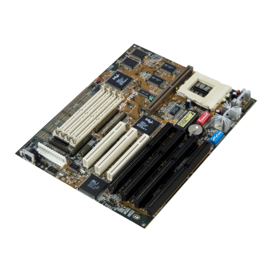
If you don’ t have a wrist strap or pad, make sure to touch a metallic object such as the system case to ground yourself before handling any compo- nents. PR5 Mainboard Layout Key 1. ISA Bus Expansion Slots 2. PCI Bus Expansion Slots 3. USB Port Connector 4. - Page 9 AB–PR5 PCI Mainboard Layout Ultra 8 2 3 7 1 PIIX3 8 2 4 3 7 V X PB SRAM 4 3 8 V X Pe ntium C P U 4 3 8 V X PB SRAM...
- Page 10 System Block Diagram...
-
Page 11: Hardware Configuration
H a r d w a r e C o n f i g u r a t i o n This chapter is about how to configure the PR5. The first section is a summary for the experienced user. The sec- ond explains the same material in detail. - Page 12 Intel Pentium CPU Vcore/Vio Settings Vcore/Vio V C 1 V C 2 V C 3 V C 4 V C 5 V C 6 V C 7 V C 8 2 . 7 V / 3 . 3 V O F F O F F O F F O F F...
-
Page 13: External Clock Frequency & External Clock Factor
Clock Generator Chip Important Note The PR5 uses one of several clock generator chips. The DS DIP switch block settings vary depending on which chip is installed. To determine the correct settings you need to know which clock chip is installed. The position of the chip on the mainboard is noted above. -
Page 14: Intel Pentium Cpus
Intel Pentium CPUs Clock Chip: PLL52C61-01 or PLL52C61-21 Ext. Clock Factor Ext. Clock Freq.: Normal/Turbo ISA Spd Refresh CPU:Ext/Int Clock D S 1 D S 2 D S 3 D S 4 D S 7 D S 5 D S 6 P 7 5 : 5 0 / 7 5 MH z O F F O F F... - Page 15 AMD–K5 CPUs (AMD-SSA/5 & AMD-K5) Clock Chip: PLL52C61-01 or PLL52C61-21 Ext. Clock Factor Ext. Clock Freq.: Normal/Turbo ISA Spd Refresh CPU:Ext/Int Clock D S 1 D S 2 D S 3 D S 4 D S 7 D S 5 D S 6 P R 7 5 : 5 0 / 7 5 M H z O F F O F F...
-
Page 16: Cyrix 6X86 Cpus
Cyrix 6x86 CPUs Clock Chip: PLL52C61-01 or PLL52C61-21 Ext. Clock Factor Ext. Clock Freq.: Normal/Turbo ISA Spd Refresh CPU:Ext/Int Clock D S 1 D S 2 D S 3 D S 4 D S 7 D S 5 D S 6 P 1 2 0 + : 5 0 / 1 0 0 M H z O F F O N O N / —... -
Page 17: Dram Installation
DRAM Installation The PR5 has numerous possible system memory configu- rations using the four 72-pin SIMM sockets and the two 168-pin DIMM sockets. The SIMM sockets work in banks of two to provide a 64-bit data path. SIMM1/SIMM2 are one bank, SIMM3/SIMM4 are another. The DIMM sock- ets are each a bank, for a total of four banks. -
Page 18: Dimm Voltage Settings
DIMM Voltage Settings The DIMM sockets support both 5-volt and 3.3-volt un- buffered DRAM. The voltage setting for both DIMM sockets is controlled by jumper JP11. The socket voltage setting must match the voltage of the DRAM on any DIMM modules you install. The jumper settings are shown below. -
Page 19: Onboard Connectors
O n b o a rd C o n n e c to rs The PR5 has onboard connector headers for the disk con- trollers, I/O ports, system enclosure connections and sev- eral other features. Pin 1 locations are noted for cable ori- entation. - Page 20 I/O Port Connectors The PR5 has two serial, one parallel, a connector for an IrDA-compatible Infrared port and a dual-port USB con- nector onboard. Combination ribbon cable to external port cables are supplied for each connector except the Infrared port. W hen installing ports, make sure the col- ored edge of the ribbon cable is at the Pin 1 end of the onboard connector.
- Page 21 Infrared & USB Port Connectors Pin Function IR Port Pin 1 +5-Volts DC Pin 2 Not used Pin 3 Receive Data Pin 4 Ground Pin 5 Transmit Data USB Ports: USB 1 – Pins 1-8, USB 2 – Pins 9-16 Pin 1 +5-Volts Pin 2...
-
Page 22: System Enclosure Connectors
System Enclosure Connectors The system enclosure (case) connections are in a header block which includes the Hardware Reset, Suspend Switch, Turbo LED, Speaker and Keylock connectors. Your system case may or may not have all of these fea- tures. The location of the connector block and the pin assignments are shown below. - Page 23 Enclosure Features Connector Block Feature Pin Function Hardware Reset Connector Pin 1 Ground Pin 2 Reset signal Suspend Switch Connector Pin 6 Ground Pin 7 Suspend Enclosure Features Connectors Turbo LED Connector Not every pin in the connector block for Pin 8 –...
-
Page 24: Other Connectors
Other Connectors There are several other connectors on the PR5, including the power input, keyboard, PS/2 mouse, IDE LED activ- ity light and CPU fan connectors. Their locations and pin assignments are shown below and at right. Power Input Connector The system power supply connector is a 12-pin connec- tor, divided into two sections, P8 and P9. - Page 25 Other Onboard Connectors Pin Function Power Input Connector J1 Pin 1 Powergood Pin 2 +5-Volts DC Pin 3 +12-Volts DC Pin 4 –12-Volts DC Power Supply Lead Connectors Pin 5 Ground Some system power supplies have two Pin 6 Ground leads that connect to the J1 power in- Pin 7 Ground...
-
Page 26: Pr5 Hardware Configuration
Quick Reference at the beginning of this section. It is in- tended for users who are less familiar with computer hardware. If your PR5 is already installed in a system you will not need much of this information unless you need to reconfigure your system. - Page 27 ISA expansion cards. Newer ISA ex- pansion cards may be able to operate at faster speeds, which provide increased performance. The PR5 can be set for slower or faster ISA Bus clock speeds. The slower speed ensures maximum com- patibility.
- Page 28 CPU. CPU Settings To configure the PR5 for the CPU you will install you have to set the switches on the two CPU configuration DIP switch blocks DS and VC. The procedure is as fol- lows: 1.
- Page 29 DS & VC DIP Switch Block Locations DS Block VC Block DS5 ISA Bus Clock Settings External Clock D S 5 Bus Clock 5 0Mh z 6 . 2 5 M H z 8 . 3 3 M H z 6 0 M H z 7 .
- Page 30 Intel Pentium CPU Clock Multiplier Factor Clock Factor D S 1 D S 2 Clock Factor x External Clock=Internal Clock Speed (in MHz) 1 . 5 O F F O F F 1.5 x 5 0 =7 5 ; 1 .5 x 6 0 =9 0 ; 1.5 x 6 6 =10 0 O F F 2 x 6 0 =1 2 0 ;...
- Page 31 Intel Pentium CPUs Clock Chip: PLL52C61-01 or PLL52C61-21 Ext. Clock Factor Ext. Clock Freq.: Normal/Turbo ISA Spd Refresh CPU:Ext/Int Clock D S 1 D S 2 D S 3 D S 4 D S 7 D S 5 D S 6 P 7 5 : 5 0 / 7 5 MH z O F F O F F...
- Page 32 AMD K5 CPU Clock Multiplier Factor Clock Factor D S 1 D S 2 Clock Factor x External Clock=Internal Clock Speed (in MHz) 1 . 5 O F F O F F 1 . 5 x 5 0 = 7 5 * ; 1 . 5 x 6 0 = 9 0 * ; 1 . 5 x 6 6 = 1 0 0 * O F F 2x60=120 (PR150);...
- Page 33 AMD–K5 CPUs (AMD-SSA/5 & AMD-K5) Clock Chip: PLL52C61-01 or PLL52C61-21 Ext. Clock Factor Ext. Clock Freq.: Normal/Turbo ISA Spd Refresh CPU:Ext/Int Clock D S 1 D S 2 D S 3 D S 4 D S 7 D S 5 D S 6 P R 7 5 : 5 0 / 7 5 M H z O F F O F F...
- Page 34 Cyrix 6x86 CPU Clock Multiplier Factor Clock Factor D S 1 D S 2 Clock Factor x External Clock=Internal Clock Speed (in MHz) O F F 2 x5 0=100 ( P 12 0+ ) ; 2x 5 5=110 ( P 13 3+ ) ; 2x 6 0=12 0 (P150+);...
- Page 35 Cyrix 6x86 CPUs Clock Chip: PLL52C61-01 or PLL52C61-21 Ext. Clock Factor Ext. Clock Freq.: Normal/Turbo ISA Spd Refresh CPU:Ext/Int Clock D S 1 D S 2 D S 3 D S 4 D S 7 D S 5 D S 6 P 1 2 0 + : 5 0 / 1 0 0 M H z O F F O N O N / —...
- Page 36 32-bit, they have to be used in pairs to create a 64- bit data path. This means that SIMM modules have to be installed in pairs. The four SIMM sockets on the PR5 are therefore divided into “ banks” of two sockets each, re- sulting in two banks.
- Page 37 The PR5 has numerous possible system memory configu- rations using the four 72-pin SIMM sockets and the two 168-pin DIMM sockets. Please note these guidelines: • Installed memory is auto-detected by the BIOS • Minimum installation 2 SIMMs or 1 DIMM mod- ule for a 64-bit data path •...
- Page 38 PR5 Memory Configuration Examples S I M M 1 / 2 S I M M 3 / 4 Total SIMM Banks 4 M B / 4 M B 8 M B You can install memory in bank 8 M B / 8 M B...
-
Page 39: Dimm Voltage Settings
DIMM Voltage Settings The DIMM sockets support both 5-volt and 3.3-volt un- buffered DRAM. The voltage setting for both DIMM sockets is controlled by jumper JP11. The socket voltage setting must match the voltage of the DRAM on any DIMM modules you install. The jumper settings are shown below. -
Page 40: Installing Memory Modules
Installing Memory Modules Installing memory modules is easy, but there are a few important precautions you should take whether you are installing SIMM or DIMM modules. The most important is to guard against damage to the modules from static discharge. A strong enough discharge can make a module unusable and ruin your investment. - Page 41 Installing DIMMs To install any kind of DIMM module do as follows: 1. Orient the short section of the edge connector so that it is at the upper end of the socket. 2. Insert the module edge into the socket at a 90° angle so that the contacts insert as far as they will go.
-
Page 42: Level 2 Cache Options
Level 2 Cache Options The Level 2 cache on the PR5 greatly speeds up system operation. There will be at least 256KB of very fast Pipe- line Burst Static RAM (SRAM) cache memory mounted either on the mainboard or on a cache module that in- stalls in the cache socket. -
Page 43: Onboard Connectors
The Floppy Disk Drive Controller connects to your sys- tem floppy drive or drives with the floppy drive ribbon cable that comes with the PR5. One end of the cable at- taches to the FDC connector on the mainboard and the other attaches to the floppy disk drive. - Page 44 The location of the connectors and their Pin 1 positions are shown in the Configuration Quick Reference. I/O Port Connectors The PR5 has two serial ports, a parallel port, an infrared port and a dual-port USB connector onboard. Combina- tion ribbon cable-to-external port cables are supplied for each connector except the infrared port.
-
Page 45: System Enclosure Connectors
The system enclosure is your system case. There are usu- ally several features built-in to the case that connect to the mainboard. The PR5 has connections for a number of these in a connector block which includes connectors for a Reset button, Suspend switch, Turbo LED, Speaker and Keyboard lock. - Page 46 AT Keyboard & PS/2 Port Pin Assignments Pin Function AT Keyboard Pin 1 Keyboard Clock Pin 2 Keyboard Data Pin 3 Not used Pin 4 Ground Pin 5 +5-Volts DC PS/2 Port Pin 1 Mouse Data Pin 2 Not used Pin 3 Ground Pin 4...
-
Page 47: Ide Activity Led Connector
IDE Activity LED Connector The IDE activity LED connector is a 4-pin connector which will accept either a 2-pin or 4-pin IDE LED activ- ity light connector. This light comes on when an IDE device in your system is being accessed. If you are con- necting a lead from an LED activity light on your case, make sure you identify which wire is the positive wire and orient the lead’... -
Page 48: Dip Switch & Jumper Summary
DIP Switch & Jumper Summary This section lists the function of all the DIP switches and jumpers on the board for your reference. DIP Switch & Jumper Functions Function DS DIP Block Switch 1 External Clock Factor Switch 2 External Clock Factor Switch 3 External Clock Frequency Switch 4... -
Page 49: Jp3: Clear Cmos Memory
Other Jumper Functions There are two other jumpers on the PR5 which have not been mentioned yet. One is JP3 (Clear CMOS Memory) and the other is JP8 (Flash ROM Type). JP3: Clear CMOS Memory The onboard CMOS memory is where the system con- figuration information set by the BIOS Setup program is stored. -
Page 50: Jp8: Flash Rom Type
JP8: Flash ROM Type This jumper is set at the factory for the type of Flash ROM chip installed. You should not change the setting and it is shown here for reference only. This jumper may be re- placed by hardwiring directly onboard on some boards. There are two types of Flash ROM chip, 5-Volt and 12- Volt. - Page 51 T e c h n i c a l I n f o r m a t i o n This section covers three topics: • CPU Specifications Detailed information on CPU specifications to help you identify precisely the CPU you want to install, so that you can determine the correct configura- tion settings.
- Page 52 Intel CPUs This section lists the specifications for Intel Pentium CPUs. The following tables use some abbreviations as follows: Power STD – 3.15V ~ 3.465V (Suggested setting 3.38V) VR – 3.3V ~ 3.465V (Suggested setting 3.38V) VRE – 3.45V ~ 3.6V (Suggested setting 3.52V) Ti m i n g STD –...
-
Page 53: Software Configuration
BIOS CMOS Setup Utility T he B I OS CM OS Se tu p U til ity Updating the BIOS The PR5 uses the Award system BIOS. The BIOS (Basic IDE Driver Disk Input Output System) is the basic software the computer needs to enable the system hardware components to operate together. - Page 54 After you press the Del key the program menu screen will appear, displaying the various sections of the Setup utility and some commands. ROM PCI/ISA BIOS(XXXXXXXX) CMOS SETUP UTILITY AWARD SOFTWARE,INC. LOAD SETUP DEFAULTS STANDARD CMOS SETUP BIOS FEATURES SETUP PASSWORD SETTING CHIPSET FEATURES SETUP IDE HDD AUTO DETECTION...
-
Page 55: Standard Cmos Setup
• Chipset Features Setup record is stored in CMOS memory which Autom atic or required settings for the PR5’ s is maintained by a battery backup. If chipset. Memory configuration feature for special- the record is lost or corrupted, or if you ized add-on cards requiring custom address space. - Page 56 Standard CMOS Setup To enter this section of the Setup program, highlight this menu item in the main menu and press the Enter key. The following screen will appear. ROM PCI/ISA BIOS(XXXXXXXX) STANDARD CMOS SETUP AWARD SOFTWARE, INC. Date (mm:dd:yy) : Wed, Aug 21 1996 Time (hh:mm:ss) : 30: 00...
- Page 57 M o d i f y To change the setting of a highlighted selection you can press either the Page Up (PU) and Page Down (PD) keys or the Plus (+) and Minus (–) keys. Press- ing a key once will switch to the next setting op- tion for the selected item.
- Page 58 Large Hard Disk Modes The last of the drive parameter entries – Mode – has three options, Normal, LBA and Large. The Mode settings are for IDE hard disks only, and it is important to understand their function. N or m a l For IDE hard disks of 528MB or less.
- Page 59 Floppy 3Mode Support 3Mode is a Japanese 3.5-inch floppy disk drive specifica- tion. If this type of drive is installed you should enable this feature. The default setting is Disabled. Video Display Types You set this according to the type of display card in your system.
- Page 60 BIOS Features Setup To enter this section of the Setup program, highlight this menu item in the main menu and press the Enter key. The following screen will appear. ROM PCI/ISA BIOS(XXXXXXXX) BIOS FEATURES SETUP AWARD SOFTWARE INC. Virus Warning : Disabled Video BIOS Shadow...
- Page 61 M o d i f y To change the setting of a highlighted selection you can press either the Page Up (PU) and Page Down (PD) keys or the Plus (+) and Minus (–) keys. Press- ing a key once will switch to the next setting op- tion for the selected item.
- Page 62 Quick Power On Self Test This feature speeds up the Power On Self Test (POST) by skipping some parts of the POST. If your system is func- tioning normally, you can enable this feature to speed the boot process. The default setting is Enabled. Boot Sequence This determines the order in which the computer checks drives for an operating system.
- Page 63 IDE HDD Block Mode This mode improves performance by making multi-sec- tor transfers from the hard disk instead of one sector per transfer. Older IDE drives may not support this feature. The default setting is Enabled. Typematic Rate Setting When enabled, you can set the two keyboard typematic controls that follow.
- Page 64 OS Select For DRAM >64MB If your system has more than 64MB of system memory installed and you are using the OS/2 operating system, set this to the OS2 setting. The default setting, Non-OS2, is for all other operating systems. Video BIOS Shadow This copies the video display card BIOS into system DRAM to increase display speed and is required for sys-...
-
Page 65: Auto Configuration
Chipset Features Setup To enter this section of the Setup program, highlight this menu item in the main menu and press the Enter key. The following screen will appear. ROM PCI/ISA BIOS(XXXXXXXX) CHIPSET FEATURES SETUP AWARD SOFTWARE INC. Auto Configuration : Enabled DRAM Timing : 70ns... - Page 66 Power Management Setup To enter this section of the Setup program, highlight this menu item in the main menu and press the Enter key. The following screen will appear. ROM PCI/ISA BIOS (XXXXXXXX) POWER MANAGEMENT SETUP AWARD SOFTWARE INC. ** Power Down & Resume Event ** Power Management : User Define IRQ3...
- Page 67 Power Management This controls the entire power management scheme. There are four settings: User Defined You set the power saving options manually Disable Turns off all power management Max Saving Maximizes power saving by activating maximum power saving settings after one minute of system inactivity Min Saving Produces less power saving by activating moder-...
- Page 68 Video Off Option This governs in what modes the video display gets turned off. The options are: Susp,Stby-> Off (Off in Suspend & Standby) Susp-> Off (Off in Suspend) All Modes Off (Off in Doze, Suspend & Standby) Always On (No video shut off) Modem Use IRQ If you have a modem installed in your system you can...
- Page 69 HDD Power Down This shuts down IDE hard disks that support a power saving mode after a specified time period. The settings range from 1 to 15 minutes and can be set manually when power management is in User Define mode. HDD Power Down does not affect SCSI hard disks.
- Page 70 PCI & Onboard I/O Setup To enter this section of the Setup program, highlight this menu item in the main menu and press the Enter key. The following screen will appear. ROM PCI/ISA BIOS(XXXXXXXX) PCI & ONBOARD I/O SETUP AWARD SOFTWARE INC. Onboard FDD Controller : Enable PCI PnP BIOS Auto-Config...
- Page 71 PCI IDE Card 2nd Channel This turns the onboard IDE controller’ s second channel on and off. If you disable this it makes IRQ15 available to the ISA expansion bus. The default setting is Enabled. PCI IDE Card IRQ Map To This item sets how the system assigns IRQs to a PCI IDE controller card installed in one of the PCI expansion slots.
- Page 72 Onboard IDE-1 Controller This turns the onboard IDE controller’ s Primary channel on and off. The default is Enabled. The two sub-items set the PIO transfer modes for the Master and Slave de- vices. The Auto setting automatically determines the best mode for the device.
- Page 73 IR Infrared Settings The next three items configure Serial Port 2 as an Infra- red port as follows: Onboard IR Function This sets the IR mode. The options are: HPSIR – HP IrDA compatibility ASKIR – Amplitude Shift Key IR Disable –...
- Page 74 Load BIOS Defaults To invoke this command highlight it in the main menu and press Enter. A message will appear asking if you want to load the BIOS defaults. Press the Y key and then the Enter key. The BIOS default settings will load. Press the N key if you want to cancel.
- Page 75 Load Setup Defaults To invoke this command highlight it in the main menu and press Enter. A message will appear asking if you want to load the Setup defaults. Press the Y key and then the Enter key. The Setup default settings will load. Press the N key if you want to cancel.
-
Page 76: Password Setting
Password Setting To invoke this command highlight it in the main menu and press Enter. A message will appear prompting you to enter a password. ROM PCI/ISA BIOS(PI-55SP4) CMOS SETUP UTILITY AWARD SOFTWARE,INC. STANDARD CMOS SETUP LOAD SETUP DEFAULTS BIOS FEATURES SETUP PASSWORD SETTING CHIPSET FEATURES SETUP IDE HDD AUTO DETECTION... -
Page 77: Ide Hdd Auto Detection
U p d at i n g T h e B I O S The PR5’ s BIOS chip is programmable and can be up- dated when new BIOS versions are released. IDE Driver Disk The PR5 comes with a floppy disk of IDE Bus master drivers for the PIIX IDE controller. -
Page 78: Technical Information
T e c h n i c a l I n f o r m a t i o n This section covers three topics: • CPU Specifications Detailed information on CPU specifications to help you identify precisely the CPU you want to install, so that you can determine the correct configura- tion settings. -
Page 79: Intel Cpus
Intel CPUs This section lists the specifications for Intel Pentium CPUs. The following tables use some abbreviations as follows: Power STD – 3.15V ~ 3.465V (Suggested setting 3.38V) VR – 3.3V ~ 3.465V (Suggested setting 3.38V) VRE – 3.45V ~ 3.6V (Suggested setting 3.52V) Ti m i n g STD –... - Page 80 75MHz Pentium C P U Internal Bus External Power C P U C P U Type Spec. Clock Factor Clock Vcore/Vio Timing Supp. Step C o mme n t P 5 4 C S Q 0 6 4 9 7 5 M H z 1 . 5 5 0 M H z STD/STD P 5 4 C S x 7 5 3 7 5 M H z 1 .
- Page 81 100MHz Pentium C P U Internal Bus External Power C P U C P U Type Spec. Clock Factor Clock Vcore/Vio Timing Supp. Step C o mme n t P 5 4 C S x 8 8 8 1 0 0 M H z 1 . 5 6 6 M H z STD/STD B - 1 P 5 4 C S x 9 1 0 1 0 0 M H z 1 .
- Page 82 120MHz Pentium C P U Internal Bus External Power C P U C P U Type Spec. Clock Factor Clock Vcore/Vio Timing Supp. Step C o mme n t P 5 4 C S S k 1 1 0 1 2 0 M H z 6 0 M H z STD/STD B - 1 Convert to P54C...
- Page 83 133MHz Pentium C P U Internal Bus External Power C P U C P U Type Spec. Clock Factor Clock Vcore/Vio Timing Supp. Step C o mme n t P 5 4 C S Q 0 7 7 2 1 3 3 M H z 6 6 M H z STD/STD B - 1 P 5 4 C S Q 0 7 7 3 1 3 3 M H z...
- Page 84 150MHz Pentium C P U Internal Bus External Power C P U C P U Type Spec. Clock Factor Clock Vcore/Vio Timing Supp. Step C o mme n t P 5 4 C S Q 0 8 3 5 1 5 0 M H z 2 . 5 6 0 M H z STD/STD P 5 4 C S S Y 0 1 5 1 5 0 M H z 2 .
- Page 85 166MHz Pentium C P U Internal Bus External Power C P U C P U Type Spec. Clock Factor Clock Vcore/Vio Timing Supp. Step C o mme n t P 5 4 C S S Y 0 1 6 1 6 6 M H z 2 . 5 6 6 M H z VRE/VRE P 5 4 C S Q 0 8 4 1 1 6 6 M H z 2 .
-
Page 86: Amd K5 Cpus
AMD K5 CPUs The diagram below shows how to interpret AMD CPU markings to determine CPU type. AMD K5 CPU Markings Package Type P–Rating: 75, 90, 100, 120, 133, 150, 166 A=SPGA (296-pin) AMD – K5 – PR100 A B Q xx Reserved 1 0 0 M H z Case Temperature... -
Page 87: Cyrix Cpus
Cyrix CPUs The diagram below shows how to interpret Cyrix CPU markings to determine CPU type. Cyrix 6x86 CPU Markings P–Rating: 90+, 120+, 133+, 150+, 166+, 200+ 6x86 – P166+ GP CPU Model 6 x 8 6 Internal Clock Speed (Core Frequency) 1 3 3 M H z 6x86L 100, 110, 120, 133, 150... -
Page 88: Ide Installation Guide
IDE Installation Guide This section is a guide to installing IDE devices in your computer system. It covers installing devices you con- nect to the mainboard’ s onboard Enhanced IDE control- ler. The main hard disk drive used in most systems is an IDE device. -
Page 89: Installing Ide Devices
IDE Cables The PR5 comes with two IDE ribbon cables to connect devices to the mainboard. Note that one edge of the cable is colored to indicate the Pin 1 side. W hen you connect... - Page 90 4. Connect the Master end of the other IDE ribbon Attach to middle of 1st IDE cable. cable to the CD-ROM drive aligning the Pin 1 po- Attach other end of 1st IDE cable to PR5 sitions and install it in the system case. IDE1 connector.
- Page 91 Pin 1 positions. Attach to end of 1st IDE cable, attach other end to PR5 IDE1 connector. 4. Plug the other end of the IDE cable onto the IDE1 connector on the mainboard with the Pin 1 posi- Hard Disk 2: Secondary Master tions aligned.
- Page 92 3. Install the Slave drive in the system case and con- Attach to end of 1st IDE cable, attach nect the IDE ribbon cable’ s Slave connector to it, other end to PR5 IDE1 connector. aligning the Pin 1 positions. Hard Disk 2: Secondary Master 4.
- Page 93 Example 6: Three Hard Disks & One CD-ROM Drive To install this configuration: 1. Make sure two hard disks are configured as Mas- ter drives and the other as a Slave drive. Most drives are set to Master at the factory. 2.
-
Page 94: Bios Setup
BIOS Setup W hen you install hard disk drives you must enter their parameters in the Standard CMOS Setup section of the BIOS CMOS Setup Utility as explained in Section 3. For new drives you should use the IDE HDD Auto Detection feature to automatically determine the drive parameters and enter them in the required locations. -
Page 95: Technical Support
Technical Support In order to help solve any problems that might arise in the course of using your PR5 mainboard we have included a few troubleshooting guidelines and some pointers about collecting information on your system to aid the techni- cal support process. -
Page 96: The Troubleshooting Form
This information makes it easier to answer questions and help solve problems. The form is on the next page. 1. Product Model: This mainboard is the PR5 2. Product Revision Number: The product version. The format is x.xx e.g. 2.11 3. - Page 97 9. System DRAM Specifications: The manufacturer, type, size and speed of the installed DRAM. For example: Panasonic, SIMM-FP DRAM, 4MB-06 or NpNX, SIMM- EDO DRAM, 8MB-06 or SEC, DIMM-S DRAM, 8MB-G12 1 0 . Coast Cache Module Specifications: The manufacturer, size and product num- ber of the installed COAST cache module.
Need help?
Do you have a question about the PR5 and is the answer not in the manual?
Questions and answers