Table of Contents
Advertisement
Quick Links
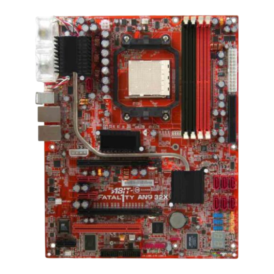
AN9 32X
Motherboard
AMD Socket AM2
User's Manual
About this Manual:
This user's manual contains all the information you may
need for setting up this motherboard. To read the user's
manual of PDF format (readable by
the "Driver & Utility CD" into the CD-ROM drive in your
system. The auto-run screen will appear, click the
"Manual" tab to enter its submenu. If not, browse the
root directory of the CD-ROM via the File Manager, and
double click the "AUTORUN" file.
Adobe
Reader), place
AMD Socket AM2
ATX Motherboard
NB: NVIDIA C51XE
SB: NVIDIA MCP55PXE
2GHz HT
Dual DDR2 800 DIMM Slots
NVIDIA SLI Technology
Dual PCI-E X16 Slots
Dual GbE LAN
IEEE 1394a
8x SATA 3Gb/s with RAID
ABIT Guru™ Technology
ABIT Silent OTES™ Technology
7.1 Channel HD Audio
Advertisement
Table of Contents

Related Manuals for Abit AN9 32X


Summary of Contents for Abit AN9 32X
- Page 1 AN9 32X Motherboard AMD Socket AM2 User’s Manual About this Manual: This user’s manual contains all the information you may need for setting up this motherboard. To read the user’s manual of PDF format (readable by Adobe the “Driver & Utility CD” into the CD-ROM drive in your system.
- Page 2 AN9 32X User’s Manual English, 1 Edition June, 2006 Copyright and Warranty Notice The information in this document is subject to change without notice and does not represent a commitment on part of the vendor, who assumes no liability or responsibility for any errors that may appear in this manual.
-
Page 3: Table Of Contents
2.7 Onboard Status Display ... 2-22 2.7.1 POST Code Displayer... 2-22 2.7.2 Power Source Indicators ... 2-23 2.8 Connecting I/O Devices... 2-24 3. BIOS Setup... 3-1 ™ 3.1 µGuru Utility...3-2 3.1.1 OC Guru ...3-2 3.1.2 ABIT EQ ...3-4 3.2 Standard CMOS Features... 3-10 AN9 32X... - Page 4 5.1 POST Code Definitions ...5-1 5.1.1 AWARD POST Code Definitions...5-1 5.1.2 AC2005 POST Code Definitions...5-4 5.2 Troubleshooting (How to Get Technical Support?) ...5-5 5.2.1 Q & A ...5-5 5.2.2 Technical Support Form ...5-8 5.2.3 UNIVERSAL ABIT Contact Information ...5-9 AN9 32X...
-
Page 5: Introduction
1. Introduction 1.1 Features & Specifications • Supports Socket 940 AM2 Processor with 2GHz system bus using Hyper-Transport™ Technology • Supports AMD CPU Cool ‘n’ Quiet Technology Chipset • Northbridge: NVIDIA • Southbridge: NVIDIA Memory • Four 240-pin DIMM slots •... - Page 6 • 2x RJ-45 Gigabit LAN ports • 4x USB 2.0 ports RoHS Compliancy • 100% Lead-free process and RoHS compliancy Miscellaneous • ATX form factor (305mm x 245mm) ※ Specifications and information contained herein are subject to change without notice. AN9 32X...
-
Page 7: Motherboard Layout
1.2 Motherboard Layout AN9 32X... - Page 8 AN9 32X...
-
Page 9: Hardware Setup
After doing this to all the slots, you can slide the board into position aligned with slots. After the board has been positioned, check to make sure everything is OK before putting the chassis back on. AN9 32X allow... -
Page 10: Checking Jumper Settings
(reserved for future use) will leave it at OPEN position. SHORT For 3-pin jumper, pin 1~2 or pin 2~3 can be shorted by plugging the jumper cap in. Pin 1~2 SHORT them OPEN Pin 2~3 SHORT OPEN AN9 32X... -
Page 11: Cmos Memory Clearing Header And Backup Battery
4. For incorrect CPU ratio/clock settings in the BIOS, press <Del> key to enter the BIOS setup menu right after powering on system. 5. Set the CPU operating speed back to its default or an appropriate value. 6. Save and exit the BIOS setup menu. AN9 32X... - Page 12 CAUTION: ※ Danger of explosion may arise if the battery is incorrectly renewed. ※ Renew only with the same or equivalent type recommended by the battery manufacturer. ※ Dispose of used batteries according to the battery manufacturer’s instructions. AN9 32X...
-
Page 13: Wake-Up Headers
Pin 1-2 shorted (Default): Disable wake-up function support at FP-USB2 port. Pin 2-3 shorted: Enable wake-up function support at FP-USB2 port • FP-PWR3: Pin 1-2 shorted (Default): Disable wake-up function support at FP-USB3 port. Pin 2-3 shorted: Enable wake-up function support at FP-USB3 port AN9 32X... -
Page 14: Connecting Chassis Components
ATX 12V 4-Pin Power Connector: This connector supplies power to CPU. The system will not start without connecting power to this one. Auxiliary 12V Power Connector: This connector provides an auxiliary power source for devices added on PCI Express slots. AN9 32X... -
Page 15: Front Panel Switches & Indicators Headers
Connects to the Suspend LED cable (if there is one) of chassis front panel. • PWR (Pin 6, 8): Connects to the Power Switch cable of chassis front panel. • PLED (Pin 16, 18, 20): Connects to the Power LED cable of chassis front panel. AN9 32X... -
Page 16: Fan Power Connectors
These connectors each provide power to the cooling fans installed in your system. • CPUFAN1: CPU Fan Power Connector • SYSFAN1: System Fan Power Connector • AUXFAN1~4: Auxiliary Fan Power Connector ※ These fan connectors are not jumpers. DO NOT place jumper caps on these connectors. AN9 32X... -
Page 17: Installing Hardware
3. The heatsink for CPU may have thermal interface material attached bottom. If not, applying a few squeeze of thermal paste to the CPU die will help to increase the contact. AN9 32X only. For detailed information on how to install the one... - Page 18 ※ A higher fan speed will be helpful for better airflow and heat-dissipation. Nevertheless, stay alert to touch any heatsink since the high temperature generated by the working system is still possible. 2-10 socket AN9 32X...
-
Page 19: Ddr2 Memory Slots
[DIMM3] and [DIMM4] are made of another same color. Usually there is no hardware or BIOS setup required after adding or removing memory modules, but you will have to clear the CMOS memory first if any memory module related problem occurs. AN9 32X 2-11... -
Page 20: Pci Express X16 Add-On Slots (Install Graphics Card)
These slots support the connections of graphics cards that comply with PCI Express specifications. This motherboard provides dual PCI-Express X16 slots for one or two graphics cards installation: One PCIE graphics card installation (Normal Mode): Insert your PCIE graphics card into [PCIEXP1] slot. 2-12 AN9 32X... - Page 21 PCIEXP1 and PCIEXP2 slots. ※ The NVIDIA SLI technology currently supports the Windows XP operating system only. 2. Bridge connecting two graphics cards with the “SLI Connector Card” (fit in both direction). Insert and secure the SLI supporting bracket. AN9 32X 2-13...
-
Page 22: Audiomax Connection Slot
• S.L./S.R. (Surround Left / Surround Right): Connects to the surround left and surround right channel in the 7.1-channel audio system. • CD1: This connector connects to the audio output of internal CD-ROM drive or add-on card. 2-14 AN9 32X... - Page 23 HD Audio. For AC’97 audio connection, you may: 1. Right-click the “Realtek HD Audio Manager” icon in system tray. 2. Click “Audio I/O” tab, and then click “Connector Settings”. AN9 32X Pin Assignment (HD AUDIO) MIC2 L AGND MIC2 R AVCC...
- Page 24 1. Remove the rubber protection-cap. Plug one end of the optical cable into the [SPDIF-Out] jack on this daughter-card. 2. Connect the other end of the optical cable to the [Digital-In] (SPDIF-In) jack on your digital multimedia device. 2-16 AN9 32X...
-
Page 25: Connecting Peripheral Devices
※ Make sure to configure the “Master” and “Slave” relation before connecting two drives by one single ribbon cable. The red line on the ribbon cable must be aligned with pin-1 on both the IDE port and the hard-drive connector. AN9 32X 2-17... -
Page 26: Serial Ata Connectors
SATA device and connect the other end from the power supply. ※ The motherboard in this illustration is served for DEMO only, may not be the same type or model as the one described in this user’s manual. 2-18 AN9 32X... -
Page 27: Additional Ieee1394 Port Headers
Each header supports 1x additional IEEE1394 port by connecting bracket or cable to the rear I/O panel or the front-mounted IEEE1394 port of your chassis. ※ Make sure the connecting cable bears the same pin assignment. AN9 32X Pin Assignment Data0 -... -
Page 28: Pci Express X1 Add-On Slots
2.6.5 PCI Express X1 Add-on Slots These slots provide the connection of add-on cards that comply with PCI Express specifications. 2.6.6 PCI Add-on Slot This slot provides the connection of add-on cards that comply with PCI specifications. 2-20 AN9 32X... -
Page 29: Guru Panel Connection Header
2.6.7 GURU Panel Connection Header This header is reserved for connecting ABIT’s exclusive GURU Panel. For more information, please refer to the included GURU Panel Installation Guide. AN9 32X 2-21... -
Page 30: Onboard Status Display
This LED device also displays the “POST” Code of AC2005, an “uGuru” chipset developed exclusively by ABIT computer. ※ The decimal point lights up during the AC2005 POST action. See Appendix for both AWARD and AC2005 POST Code definitions. 2-22 AN9 32X... -
Page 31: Power Source Indicators
Lights On: The system power is on. Lights Off: The system power is off. • SLI_PWR1: Lights On: The system power is on. Lights Off: The “ATX4P1” connector is connected with power source from your ATX power supplier. AN9 32X 2-23... -
Page 32: Connecting I/O Devices
Keyboard: Connects to PS/2 keyboard. • LAN1/LAN2: Connects to Local Area Network. • USB1/USB2: Connects to USB devices such as scanner, digital speakers, monitor, mouse, keyboard, hub, digital camera, joystick etc. 2-24 ™ (Silent Outside Thermal Exhaust System) is a device AN9 32X... -
Page 33: Bios Setup
BIOS menu. The BIOS setup screens and descriptions illustrated in this manual are for your reference only, and may not completely match with what you see on your screen. AN9 32X ► PnP/PCI Configurations Load Fail-Safe Defaults... -
Page 34: Μguru Utility
There are two setup menus in this µGuru utility. You may switch between these two by clicking the left or right arrow key on keyboard: 3.1.1 OC Guru OC Guru AMD Athlon(tm) 64 X2 Dual Core Processor 3800+ Frequency : 2000MHz CPU Operating Speed X - Multiplier Factor... - Page 35 PC Reset Button Cycles PC Power Cycles AC Power On Total Time AC Power Cycles ↓↑→←:Move Enter:Select +/-/PU/PD:Value These items display the power cycle statistics for each element. AN9 32X µGuru Utility V1.00 0 Hours 119 Hours 123 Cycles 538 Cycles...
-
Page 36: Abit Eq
µGuru Utility V1.00 Reading Shutdown Shutdown Enable Temp. 34°C/93°F (*) 85°/185°F 29°C/84°F ( ) 65° 36°C/96°F ( ) 90° Item Help ► F10:Save ESC:Exit Beep Beep Enable Temp. 75°C/167°F ° C/149°F (*) 55°C/131°F ° C/194°F (*) 88°C/176°F F10:Save ESC:Exit AN9 32X... -
Page 37: Voltage Monitoring
These items display the voltage of each element. Shutdown Enable Use <Space> key to enable system shutdown function. If the voltage of corresponding element is higher/lower than the high/low limit, the system will automatically shutdown. AN9 32X µGuru Utility V1.00 Reading Shutdown... -
Page 38: Fan Speed Monitoring
Low Limit These items set the low limit of fan speed. µGuru Utility V1.00 Reading Shutdown Enable 7440 RPM Beep Enable Limit 300 RPM 300 RPM 300 RPM 300 RPM 300 RPM 300 RPM F10:Save ESC:Exit AN9 32X... - Page 39 This item selects the reference point for taking temperature among the available options of CPU, SYS, and PWM Temperature, but there is only one “CPU Temperature” item to choose for the “CPU FanEQ Control”. AN9 32X µGuru Utility V1.00 Press Enter...
- Page 40 These items set the high and low voltage limit that you want to provide the fan with. ※ The value of high limit must be set above the one of low limit. µGuru Utility V1.00 Enabled System Temperature 40°C/104°F 30°C/86°F 12.0 V 8.0 V Item Help ►►► F10:Save ESC:Exit AN9 32X...
- Page 41 DC Fan Voltage High/Low These items set the high and low voltage limit that you want to provide the fan with. ※ The value of high limit must be set above the one of low limit. AN9 32X µGuru Utility V1.00 Enabled System Temperature 40°C/104°F...
-
Page 42: Standard Cmos Features
Standard CMOS Features Thu. May 25 2006 12 : 34 : 56 None None None None None None None None 1.44M, 3.5 in. None Disabled All, But keyboard 640K 1046520K 1047552K F6: Fail-Safe Defaults Item Help F7: Optimized Defaults AN9 32X... - Page 43 This item displays the approximate capacity of the disk drive. Usually the size is slightly greater than the size of a formatted disk given by a disk-checking program. Cylinder This item configures the number of cylinders. AN9 32X IDE Channel 1 Master Press Enter Auto...
- Page 44 640K for system with 640K or more memory size installed on the motherboard. Extended Memory This item displays the amount of extended memory detected during system boot-up. Total Memory This item displays the total memory available in the system. 3-12 AN9 32X...
-
Page 45: Advanced Bios Features
Enabled, if the BIOS detects no floppy drive, it will display a floppy disk drive error message. If this item is disabled, the BIOS will skip this test. The default setting is Disabled. AN9 32X Advanced BIOS Features... - Page 46 MPS Version Ctrl For OS This item specifies which version of MPS (Multi-Processor Specification) this motherboard will use. Leave this item at its default setting. Full Screen LOGO Show This item determines if the full screen logo is shown when booting. 3-14 AN9 32X...
-
Page 47: Advanced Chipset Features
This item adjusts the bus clock for “PCIEXP2” slot. NB<->SB Reference clock This item adjusts the bus clock between NB and SB. PCI Express bus(NB) This item adjusts the bus clock for “PCIEXP1” slot. AN9 32X Advanced Chipset Features Auto Auto Auto... - Page 48 105 ns 75 ns 75 ns 75 ns 4 Clocks 2 Clocks 17 Clocks 4 Clocks 2 Clocks 4 Clocks 12 Clocks Enabled Disabled Disabled Disabled Disabled Disabled Disabled Disabled Enabled F6: Fail-Safe Defaults Item Help F7: Optimized Defaults AN9 32X...
-
Page 49: Integrated Peripherals
Click <Enter> key to enter its submenu: Phoenix – Award BIOS CMOS Setup Utility ► IDE Function Setup ► RAID Configuration ↓↑→←:Move Enter:Select +/-/PU/PD:Value F10:Save ESC:Exit F1:General Help F5: Previous Values AN9 32X Integrated Peripherals Press Enter PCIEXP1 V1.1+V2.0 Auto... -
Page 50: Ide Function Setup
This item enables or disables the IDE HDD Block Mode. Serial-ATA Controller This item enables or disables the on-chip SATA controller. 3-18 IDE Function Setup Enabled Enabled Enabled All Enabled F6: Fail-Safe Defaults Item Help F7: Optimized Defaults AN9 32X... -
Page 51: Raid Configuration
Select the type of USB controller. Three options are available: Disabled The default setting is V1.1+V2.0. If you choose to disable this item, the “USB Keyboard Support” and “USB Mouse Support” items will not be available to select in Integrated Peripherals menu. AN9 32X RAID Configuration Disabled Disabled... - Page 52 [RAID]: The on-chip Serial ATA served as RAID mode. SATA Option ROM This item allows you to use the boot ROM of onboard Serial ATA RAID to boot up system. Onboard 1394 Controller: This option enables or disables the IEEE 1394 controller. 3-20 AN9 32X...
-
Page 53: Power Management Setup
Wakeup by PME# of PCI When set to [Enabled], access through the add-on PCI card can remotely wake up the system that was in Soft-Off condition. The PCI card must support the wake up function. AN9 32X Power Management Setup S3(Suspend-To-RAM) - Page 54 This item sets the time you would like the system to power-on. Cool ’n’ Quiet Technology: This option enables or disables the AMD K8 cool and quiet function. Power On Function This item selects the way you want your system to power on.
- Page 55 If the system’s power is off when AC power failure occurs, it will remain off when power returns. If the system’s power is on when AC power failure occurs, the system will power-on when power returns. AN9 32X 3-23...
-
Page 56: Pnp/Pci Configurations
This item configures all of the boot and Plug-and-Play compatible devices. [Auto(ESCD)]: The system will automatically detect the settings. [Manual]: Choose the specific IRQ resources in the “IRQ Resources” menu. 3-24 PnP/PCI Configurations Auto(ESCD) Press Enter Disbaled 4096 F6: Fail-Safe Defaults Item Help F7: Optimized Defaults AN9 32X... - Page 57 [Disabled]: MPEG ISA/VESA VGA cards do not work with PCI/VGA. [Enabled]: MPEG ISA/VESA VGA cards work with PCI/VGA. Maximum Payload Size This item sets the maximum TLP payload size for the PCI Express devices. AN9 32X - IRQ Resources Reserved PCI Device...
-
Page 58: Load Fail-Safe Defaults
This option protects the BIOS configuration or restricts access to the computer itself. 3.11 Save & Exit Setup This option saves your selections and exits the BIOS setup menu. 3.12 Exit Without Saving This option exits the BIOS setup menu without saving any changes. 3-26 AN9 32X... -
Page 59: Driver & Utility Cd
[ABIT Utility]: Click on this tab to enter the menu for installing utilities exclusively developed by ABIT. • Browse CD]: Click to browse the contents of this “Driver & Utility CD”. • Close]: Click to exit this installation menu. AN9 32X... -
Page 60: Nvidia Nforce Chipset Driver
Click the [nVidia nForce Chipset Driver]. The following screen appears: Follow the prompts on the screen to complete installation. Restart the system for the driver to take effect. ※ Please install this nVidia nForce Chipset Driver first after having installed the Windows operating system. AN9 32X... -
Page 61: Realtek Hd Audio Driver
Click the [Realtek HD Audio Driver] item. The following screen appears: Follow the prompts on the screen to complete installation. Restart the system for the driver to take effect. ※ Install this Driver after having installed the “AudioMAX” daughter-card. AN9 32X... -
Page 62: Silicon Image 3132 Raid Driver
Click on the [Drivers] tab in the installation menu screen. Click the [Silicon Image 3132 RAID Driver] item. The following screen appears: Follow the prompts on the screen to complete installation. Restart the system for the driver to take effect. AN9 32X... -
Page 63: Cool'n'quiet Driver
To install this driver: Click on the [Drivers] tab in the installation menu screen. Click the [Cool’n’Quiet Driver] item. The following screen appears: Follow the prompts on the screen to complete installation. Restart the system for the driver to take effect. AN9 32X... - Page 64 “Minimal Power Management” to enable Cool ‘n’ Quiet. ※ For Windows 2000 or ME system, an AMD Cool ‘n’ Quiet tab will appear under “Power Options” when the Cool ‘n’ Quiet software for Windows 2000 and ME is installed.
-
Page 65: Usb 2.0 Driver
Click on the [ABIT Utility] tab in the installation menu screen. Click the [ABIT Guru] item. The following screen appears: Follow the prompts on the screen to complete installation. Restart the system for the driver to take effect. AN9 32X... -
Page 66: Nvraid Floppy Disk
Insert one blank floppy disk to the selected floppy drive and click [Build]. Click [OK] to finish building the SATA Driver Disk. ※ If you are using a windows 2000 operating system, please update your system to Service Pack 4 before starting to setup the NVIDIA RAID. AN9 32X... -
Page 67: Appendix
1. Check validity of RTC value: e.g. a value of 5Ah is an invalid value for RTC minute. 2. Load CMOS settings into BIOS stack. If CMOS checksum fails, use default value instead. Prepare BIOS resource map for PCI & PnP use. If ESCD is valid, take into consideration of the ESCD’s legacy information. AN9 32X... - Page 68 Initialize EISA slot 1. Calculate total memory by testing the last double word of each 64K page 2. Program writes allocation for AMD K5 CPU 1. Program MTRR of M1 CPU 2. Initialize L2 cache for P6 class CPU & program CPU with proper cacheable range 3.
- Page 69 Update keyboard LED & typematic rate 1. Build MP table 2. Build & update ESCD 3. Set CMOS century to 20h or 19h 4. Load CMOS time into DOS timer tick 5. Build MSIRQ routing table Boot attempt (INT 19h) AN9 32X E8POST.ASM starts...
-
Page 70: Ac2005 Post Code Definitions
9.7. Check CPU core voltage 9.8. De-Assert ATX power supply 9.9. Complete power off sequence F.0. Button reset F.1. SoftMenu reset F.2. Power on sequence timeout F.3. Power off sequence timeout Power On Sequence Power Off Sequence Others AN9 32X... -
Page 71: Troubleshooting (How To Get Technical Support?)
If the situation remains the same, try Step 3. Step 3. The same procedure as Step 2, but while discharging the CMOS data, pull out the ATX power connectors from motherboard and remove the button battery during CMOS discharge. AN9 32X... - Page 72 CPU: Type in the brand name and the speed (MHz) of your CPU. (Illustrate the over-clocking status if you had done so.) Example: Intel 650 3.4GHz (OC FSB=220MHz) • Memory brand: Type in the brand and model name of your memory module. Example: Memory brand: Kingston (KVR533D2N4/1G) AN9 32X...
- Page 73 Q. Is the motherboard dead? Do I need to return it to where I bought from or go through an RMA process? A: After you had gone through the troubleshooting procedures, yet the problem still exists, or you find an evident damage on the motherboard. Please contact our RMA center. (http://www2.abit.com.tw/page/en/contact/index.php?pFUN_KEY=18000&pTITLE_IMG) AN9 32X...
-
Page 74: Technical Support Form
5.2.2 Technical Support Form Country: First name: Last Name: Subject: Motherboard: BIOS Version: CPU: Memory brand: Memory size: Memory configuration: Graphics card: Graphics driver version: Power supply maker: Power supply wattage: Storage devices: Optical devices: Other devices: Operating system: Problem description: AN9 32X... -
Page 75: Universal Abit Contact Information
Website: http://www.abit.com.cn Poland ABIT Computer (Poland) Co. Ltd. Przedstawicielstwo w Polsce, ul. Wita Stwosza 28, 50-149 Wrocław Tel: 48 71 780 78 65 (Technical support/RMA) Tel: 48 71 718 19 70 (PR/Marketing) Fax: 48 71 780 78 66 AN9 32X... - Page 76 http://www.abit.com.tw P/N: 4310-0000-18 Rev. 1.00...
Need help?
Do you have a question about the AN9 32X and is the answer not in the manual?
Questions and answers