Table of Contents
Advertisement
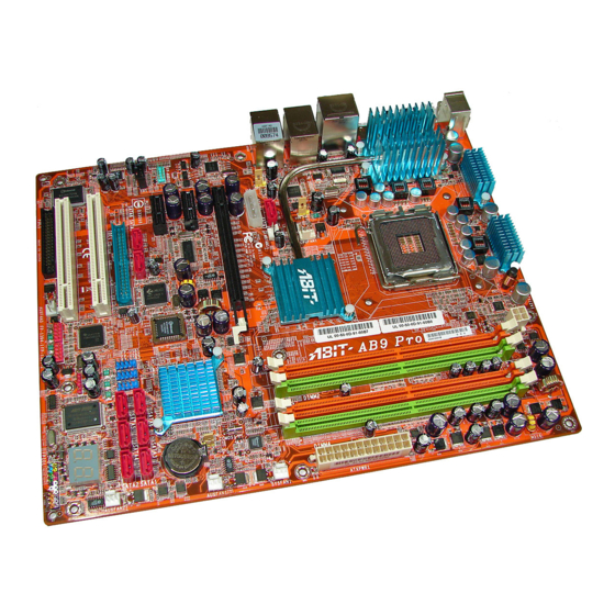
AB9 Pro/AB9
Motherboard
Socket 775
Intel Core 2 Duo
Intel Pentium 4
Intel Pentium D
User's Manual
About this Manual:
This user's manual contains all the information you may
need for setting up this motherboard. To read the user's
manual of PDF format (readable by
the "Driver & Utility CD" into the CD-ROM drive in your
system. The auto-run screen will appear, click the
"Manual" tab to enter its submenu. If not, browse the
root directory of the CD-ROM via the File Manager, and
double click the "AUTORUN" file.
Adobe
Reader), place
LGA775 ATX Motherboard
Intel 965 / ICH8R (AB9 Pro)
1066MHz FSB
Dual DDR2 800
Dual GbE LAN (AB9 Pro)
IEEE 1394
10x SATA 3Gb/s (AB9 Pro)
HD 7.1
Silent OTES™ Technology
uGuru™ Technology
Advertisement
Table of Contents

Related Manuals for Abit AB9 Pro


Summary of Contents for Abit AB9 Pro
- Page 1 “Manual” tab to enter its submenu. If not, browse the root directory of the CD-ROM via the File Manager, and double click the “AUTORUN” file. LGA775 ATX Motherboard Intel 965 / ICH8R (AB9 Pro) 1066MHz FSB Dual DDR2 800 Dual GbE LAN (AB9 Pro)
- Page 2 No part of this manual may be reproduced, transmitted or transcribed without the expressed written permission of the manufacturer and authors of this manual. If you do not properly set the motherboard settings, causing the motherboard to malfunction or fail, we cannot guarantee any responsibility.
-
Page 3: Table Of Contents
Contents 1. Introduction ... 1-1 1.1 Features & Specifications ...1-1 1.2 Motherboard Layout...1-3 1.2.1 AB9 Pro ...1-3 1.2.2 AB9...1-4 2. Hardware Setup ... 2-1 2.1 Choosing a Computer Chassis ...2-1 2.2 Installing Motherboard ...2-1 2.3 Checking Jumper Settings ...2-2 2.3.1 CMOS Memory Clearing Header and Backup Battery ...2-3 2.3.2 Wake-up Header ...2-5... - Page 4 5.1 POST Code Definitions ...5-1 5.1.1 AWARD POST Code Definitions...5-1 5.1.2 AC2005 POST Code Definitions...5-4 5.2 Troubleshooting (How to Get Technical Support?) ...5-5 5.2.1 Q & A ...5-5 5.2.2 Technical Support Form ...5-8 5.2.3 Universal ABIT Contact Information ...5-9 AB9 Pro, AB9...
-
Page 5: Introduction
® • Support Intel Core 2 Duo, Pentium 1066/800/533MHz FSB Chipset • Intel P965 / ICH8R (AB9 Pro) • Intel P965 / ICH8 (AB9) Memory • 4x 240-pin DIMM slots • Supports Dual Channel DDR2 800/667/533 Un-buffered Non-ECC memory • Supports maximum memory capacity up to 8GB •... - Page 6 • 4x SATA 3Gb/s offered by Intel ICH8 (AB9) • 2x SATA 3Gb/s offered by JMicron JMB363 supports up to 0, 1, JBOD RAID function • 2x SATA 3Gb/s offered by Silicon Image 3132 (AB9 Pro) ABIT Engineered • ABIT SoftMenu ™...
-
Page 7: Motherboard Layout
1.2 Motherboard Layout 1.2.1 AB9 Pro AB9 Pro, AB9... -
Page 8: Ab9
1.2.2 AB9 AB9 Pro, AB9... -
Page 9: Hardware Setup
2.1 Choosing a Computer Chassis • This motherboard carries an ATX form factor of 305 x 245 mm. Choose a chassis big enough to install this motherboard. • As some features for this motherboard are implemented by cabling connectors on the motherboard to indicators and switches or buttons on the chassis, make sure your chassis supports all the features required. -
Page 10: Checking Jumper Settings
(reserved for future use) will leave it at OPEN position. SHORT For 3-pin jumper, pin 1~2 or pin 2~3 can be shorted by plugging the jumper cap in. Pin 1~2 SHORT them OPEN Pin 2~3 SHORT OPEN AB9 Pro, AB9... -
Page 11: Cmos Memory Clearing Header And Backup Battery
4. For incorrect CPU ratio/clock settings in the BIOS, press <Del> key to enter the BIOS setup menu right after powering on system. 5. Set the CPU operating speed back to its default or an appropriate value. 6. Save and exit the BIOS setup menu. AB9 Pro, AB9... - Page 12 ※ Danger of explosion may arise if the battery is incorrectly renewed. ※ Renew only with the same or equivalent type recommended by the battery manufacturer. ※ Dispose of used batteries according to the battery manufacturer’s instructions. AB9 Pro, AB9...
-
Page 13: Wake-Up Header
Pin 1-2 shorted (Default): Disable wake-up function support at USB1 port. Pin 2-3 shorted: Enable wake-up function support at USB1 port. • USB-PWR2: Pin 1-2 shorted (Default): Disable wake-up function support at USB2 port. Pin 2-3 shorted: Enable wake-up function support at USB2 port AB9 Pro, AB9... -
Page 14: Connecting Chassis Components
ATX 12V 4-Pin Power Connector: This connector supplies power to CPU. The system will not start without connecting power to this one. Auxiliary 12V Power Connector: This connector provides an auxiliary power source for devices added on PCI Express slots. AB9 Pro, AB9... -
Page 15: Front Panel Switches & Indicators Headers
Connects to the Suspend LED cable (if there is one) of chassis front panel. • PWR (Pin 6, 8): Connects to the Power Switch cable of chassis front panel. • PLED (Pin 16, 18, 20): Connects to the Power LED cable of chassis front panel. AB9 Pro, AB9... -
Page 16: Fan Power Connectors
CPUFAN1: CPU Fan Power Connector • NBFAN1: Chipset Fan Power Connector • SYSFAN1: System Fan Power Connector • AUXFAN1~3: Auxiliary Fan Power Connector ※ These fan connectors are not jumpers. DO NOT place jumper caps on these connectors. AB9 Pro, AB9... -
Page 17: Installing Hardware
2.5 Installing Hardware ※ DO NOT scratch the motherboard when installing hardware. An accidentally scratch of a tiny surface-mount component may seriously damage the motherboard. ※ In order to protect the contact pins, please pay attention to these notices: 1. A maximum 20 cycles of CPU installation is recommended. - Page 18 PUT ON the cap after operation or testing. 6. Lower the plate onto the CPU package. Engage the load lever while gently pressing down the load plate. 7. Secure the lever with the hook under retention tab. 2-10 AB9 Pro, AB9...
- Page 19 ※ A higher fan speed will be helpful for better airflow and heat-dissipation. Nevertheless, stay alert to touch any heatsink since the high temperature generated by the working system is still possible. AB9 Pro, AB9 2-11...
-
Page 20: Ddr2 Memory Slots
2.5.2 DDR2 Memory Slots This motherboard provides four 240-pin DIMM slots for Dual Channel DDR2 800/667/533 memory modules with memory expansion size up to 8GB. • To reach the optimum performance in dual-channel configurations, install identical DDR2 DIMM pairs for each channel. - Page 21 ※ Static electricity can damage the electronic components of the computer or optional boards. Before starting these procedures, ensure that you are discharged of static electricity by touching a grounded metal object briefly. AB9 Pro, AB9 Channel B DIMM2 DIMM3...
-
Page 22: Connecting Peripheral Devices
※ During the OS installation, you will have to install the third-party driver for devices connected to “SATA8”, “SATA9”, and “IDE1” connector. Press <F6> key, and then insert its driver disk into floppy disk drive when the screen instruction prompts you to install a third-party SCSI or RAID driver. 2-14 AB9 Pro, AB9... -
Page 23: Serial Ata Connectors
• SATA1~SATA6: Available for RAID 0, RAID 1, RAID 5, or RAID 10 configuration. (Supports up to 4 disks for RAID 0/10/5, or up to 2 disks for RAID 1) (For model “AB9 Pro”) • SATA8~SATA9: Available for RAID 0, RAID 1, or JBOD configuration. -
Page 24: Additional Usb 2.0 Port Headers
2.6.3 Additional USB 2.0 Port Headers Besides the 4x USB 2.0 ports located at rear I/O part, this motherboard also features 2x more USB 2.0 headers onboard. Each header supports 2x additional USB 2.0 ports by connecting bracket or cable to the rear I/O panel or the front-mounted USB ports of your chassis. -
Page 25: Internal Audio Connectors
Audio, yet for AC’97 Audio CODEC connection, you must carefully check the pin assignment before connecting from the front panel module. An incorrect connection may cause malfunction or even damage the motherboard. ※ Please do not connect the “Ground” cable or “USB VCC” cable from the front panel module to the Pin 4 “AVCC”... - Page 26 The audio driver is originally configured to support HD Audio. For AC’97 audio connection, you may: 1. Right-click the “Realtek HD Audio Manager” icon in system tray. 2. Click “Audio I/O” tab, and then click “Connector Settings”. 3. Click “Disabled front panel jack detection”, and then click “OK” to confirm. 2-18 AB9 Pro, AB9...
-
Page 27: Pci And Pci Express X16, X1 Slots
2.6.7 PCI and PCI Express X16, X1 Slots Install PCI Express X16 graphics card into slot “PCIEXP1”. Install PCI Express X1 cards into slots “PCIE1” and/or “PCIE2”. Install PCI cards into slots “PCI1” and/or “PCI2”. AB9 Pro, AB9 2-19... -
Page 28: Guru Panel Connection Header
2.6.8 GURU Panel Connection Header This header is reserved for connecting ABIT’s exclusive GURU Panel. For more information, please refer to the included GURU Panel Installation Guide. 2-20 AB9 Pro, AB9... -
Page 29: Onboard Status Display
POST Code in address 80h to find out where the problem lies. This LED device also displays the “POST” Code of AC2005, an “uGuru” chipset developed exclusively by Universal ABIT. ※ The decimal point lights up during the AC2005 POST action. -
Page 30: Power Source Indicators
2.7.2 Power Source Indicators These indicators work as a reminding device to display the power status of this motherboard with power source connected. • 5VSB: This LED lights up when the power supply is connected with power source. • VCC: This LED lights up when the system power is on. -
Page 31: Connecting Rear Panel I/O Devices
OPT-IN1: This connector provides an S/PDIF-In connection through optical fiber to digital multimedia devices. • OPT-OUT1: This connector provides an S/PDIF-Out connection through optical fiber to digital multimedia devices. • eSATA1: This connector supports the external SATA connection. (For model “AB9 Pro”) AB9 Pro, AB9 2-23... - Page 32 Mic-In: Connects to the plug from external microphone. • LAN1: Connects to Local Area Network. • LAN2: Connects to Local Area Network. (For model “AB9 Pro”) • USB1/USB2: Connects to USB devices such as scanner, digital speakers, monitor, mouse, keyboard, hub, digital camera, joystick etc.
-
Page 33: Bios Setup
3. BIOS Setup This motherboard provides a programmable EEPROM so that you can update the BIOS utility. The BIOS (Basic Input/Output System) is a program that deals with the basic level of communication between processor and peripherals. Use the BIOS Setup program only when installing motherboard, reconfiguring system, or prompted to “Run Setup”. -
Page 34: Μguru Utility
This item displays the CPU model name installed on this motherboard. Frequency This item displays the processor speed of the CPU installed on this motherboard. CPU Operating Speed This item displays the CPU operating speed according to the type and speed of your CPU. You can also select the [User Define] option to enter the manual option. - Page 35 The option “User Define” enables you to select the following voltages manually. CPU Core Voltage DDR2 Voltage MCH 1.25V Voltage ICHIO 1.5V Voltage AB9 Pro, AB9...
-
Page 36: Power Cycle Statistics
↓↑→←:Move Enter:Select +/-/PU/PD:Value These items display the power cycle statistics for each element. 3.1.2 ABIT EQ Click right-arrow <→> key to switch from OC Guru setup menu to ABIT EQ setup menu: ABIT EQ ABIT EQ Beep Control ► Temperature Monitoring ►... -
Page 37: Temperature Monitoring
CPU/System/PWM’s temperature exceeded the beep temperature limit, warning beeps will sound. Beep Temp. This item selects the warning temperature limit. ※ The shutdown temperature must be set above the warning temperature. AB9 Pro, AB9 µGuru Utility v1.00C Reading Shutdown Shutdown Enable Temp. -
Page 38: Voltage Monitoring
1.45 V 0.95 V 1.50 V 1.00 V 1.80 V 1.20 V 1.25 V 0.85 V 14.40 V 9.60 V 14.40 V 9.60 V 6.00 V 4.00 V 3.95 V 2.65 V 6.00 V 4.00 V F10:Save ESC:Exit AB9 Pro, AB9... -
Page 39: Fan Speed Monitoring
Use <Space> key to enable warning beeps function. If the fan speed is lower than the low limit value, warning beeps will sound. Low Limit These items set the low limit of fan speed. AB9 Pro, AB9 µGuru Utility v1.00C Reading Shutdown... - Page 40 Enabled CPU Temperature 76°C/168°F 66°C/150°F 100 % 60 % Enabled SYS Temperature 40°C/104°F 30°C/86°F 12.0 V 8.0 V Enabled SYS Temperature 40°C/104°F 30°C/86°F 12.0 V 8.0 V Item Help ►► F10:Save ESC:Exit Item Help ►►► F10:Save ESC:Exit AB9 Pro, AB9...
- Page 41 This item selects the reference point for taking temperature among the available options of CPU, SYS, and PWM Temperature, but there is only one “CPU Temperature” item to choose for the “CPU FanEQ Control”. AB9 Pro, AB9 µGuru Utility V1.00 Enabled SYS Temperature 40°C/104°F...
- Page 42 DC Fan Voltage High/Low These items set the high and low voltage limit that you want to provide the fan with. ※ The value of high limit must be set above the one of low limit. 3-10 AB9 Pro, AB9...
-
Page 43: Standard Cmos Features
This item sets the date you specify (usually the current date) in the format of [Month], [Date], and [Year]. Time (hh:mm:ss) This item sets the time you specify (usually the current time) in the format of [Hour], [Minute], and [Second]. AB9 Pro, AB9 Standard CMOS Features Tue. Aug 1 2006 12 : 34 : 56 None... - Page 44 Cylinder This item configures the numbers of cylinders. 3-12 IDE Channel 1 Master Press Enter Auto Auto 0 MB F6: Fail-Safe Defaults Item Help F7: Optimized Defaults AB9 Pro, AB9...
- Page 45 640K for system with 640K or more memory size installed on the motherboard. Extended Memory This item displays the amount of extended memory detected during system boot-up. Total Memory This item displays the total memory available in the system. AB9 Pro, AB9 3-13...
-
Page 46: Advanced Bios Features
Press Enter Press Enter Enabled Floppy Hard Disk SATA CDROM Enabled Disabled Setup Enabled F6: Fail-Safe Defaults Advanced BIOS Features Disabled Auto Enabled Enabled Enabled F6: Fail-Safe Defaults Item Help F7: Optimized Defaults Item Help F7: Optimized Defaults AB9 Pro, AB9... - Page 47 Set [Boot Other Device] to [Enabled] if you wish to boot from another device other than these three items. Boot Up Floppy Seek When set to [Enabled], the BIOS will check whether the floppy disk drive is installed or not. AB9 Pro, AB9 3-15...
- Page 48 But by doing this, you will have to reset all previously set options. MPS Version Ctrl For OS This item specifies which version of MPS (Multi-Processor Specification) this motherboard will use. Leave this item at its default setting.
-
Page 49: Advanced Chipset Features
This item controls the number of DRAM clocks used for the DRAM parameters. PCI-E Compliancy Mode This item selects the mode for PCI Express add-on card. Init Display First This item allows you to choose the primary display card. AB9 Pro, AB9 Advanced Chipset Features By SPD Auto Auto... -
Page 50: Integrated Peripherals
:Move Enter:Select +/-/PU/PD:Value F10:Save ESC:Exit F1:General Help F5: Previous Values 3-18 Integrated Peripherals Press Enter Press Enter Press Enter Press Enter F6: Fail-Safe Defaults OnChip IDE Device Enabled F6: Fail-Safe Defaults Item Help F7: Optimized Defaults Item Help F7: Optimized Defaults AB9 Pro, AB9... -
Page 51: Onchip Pci Device
USB 2.0 Controller This option enables or disables the USB 2.0 controller. USB Keyboard Support via Select [BIOS] for the legacy operating system (such as DOS) that does not support USB keyboard. AB9 Pro, AB9 OnChip PCI Device Enabled Enabled Enabled... -
Page 52: Onboard Pci Device
F5: Previous Values Onboard LAN 1 Controller This option enables or disables the LAN1 controller. Onboard LAN 2 Controller (For model “AB9 Pro”) This option enables or disables the LAN2 controller. Invoke Boot Agent This item allows you to use the boot ROM (instead of a disk drive) to boot up the system and access the local area network directly. -
Page 53: Power Management Setup
When set to [Enabled], this item allows you to use a USB device to wake up a system that is in the S3 (STR - Suspend To RAM) state. This item can be configured only if the item “ACPI Suspend Type” is set to [S3(STR)]. AB9 Pro, AB9 Power Management Setup S3(Suspend-To-RAM) - Page 54 When set to [Enabled], access through the onboard LAN1 port can remotely wake up the system that was in Soft-Off condition. Wake Up by Onboard LAN2 (AB9 Pro) When set to [Enabled], access through the onboard LAN2 port can remotely wake up the system that was in Soft-Off condition.
- Page 55 If the system’s power is off when AC power failure occurs, it will remain off when power returns. If the system’s power is on when AC power failure occurs, the system will power-on when power returns. AB9 Pro, AB9 3-23...
-
Page 56: Pnp/Pci Configurations
This item configures all of the boot and Plug-and-Play compatible devices. [Auto(ESCD)]: The system will automatically detect the settings. [Manual]: Choose the specific IRQ resources in the “IRQ Resources” menu. 3-24 PnP/PCI Configurations Auto(ESCD) Press Enter Disbaled F6: Fail-Safe Defaults Item Help F7: Optimized Defaults AB9 Pro, AB9... - Page 57 [Enabled]: MPEG ISA/VESA VGA cards work with PCI/VGA. [Disabled]: MPEG ISA/VESA VGA cards do not work with PCI/VGA. Maximum Payload Size This item sets the maximum TLP payload size for the PCI Express devices. AB9 Pro, AB9 IRQ Resources PCI Device PCI Device...
-
Page 58: Load Fail-Safe Defaults
This option protects the BIOS configuration or restricts access to the computer itself. 3.11 Save & Exit Setup This option saves your selections and exits the BIOS setup menu. 3.12 Exit Without Saving This option exits the BIOS setup menu without saving any changes. 3-26 AB9 Pro, AB9... -
Page 59: Driver & Utility Cd
[Manual]: Click to enter the user’s manual menu. • [Utility]: Click to enter the utilities installation menu. • [ABIT Utility]: Click to enter the installation menu of utilities exclusively developed by ABIT. • Browse CD]: Click to browse the contents of this “Driver & Utility CD”. -
Page 60: Intel Chipset Software Installation Utility
Click on the [Drivers] tab in the installation menu screen. Click the [Intel Chipset Software Installation Utility] item. The installation screen appears: Follow the prompts on the screen to complete installation. Restart the system for the driver to take effect. AB9 Pro, AB9... -
Page 61: Intel Matrix Storage Technology Driver
Click on the [Drivers] tab in the installation menu screen. Click the [Intel Matrix Storage Technology Driver] item. The installation screen appears: Follow the prompts on the screen to complete installation. Restart the system for the driver to take effect. AB9 Pro, AB9 SATA Mode Select “RAID”. -
Page 62: Realtek Audio Driver
Click on the [Drivers] tab in the installation menu screen. Click the [Audio Driver] item. The installation screen appears: Follow the prompts on the screen to complete installation. Restart the system for the driver to take effect. AB9 Pro, AB9... -
Page 63: Realtek Lan Driver
Click on the [Drivers] tab in the installation menu screen. Click the [LAN Driver] item. The installation screen appears: Follow the prompts on the screen to complete installation. Restart the system for the driver to take effect. AB9 Pro, AB9... -
Page 64: Silicon Image 3132 Sata Driver
Click on the [Drivers] tab in the installation menu screen. Click the [Sil3132 SATA Driver] item. The installation screen appears: Follow the prompts on the screen to complete installation. Restart the system for the driver to take effect. AB9 Pro, AB9... -
Page 65: Jmicron Sata Driver
Click on the [Drivers] tab in the installation menu screen. Click the [JMicron SATA Driver] item. The installation screen appears: Follow the prompts on the screen to complete installation. Restart the system for the driver to take effect. AB9 Pro, AB9... -
Page 66: Usb 2.0 Driver
To install this utility: Click on the [ABIT Utility] tab in the installation menu screen. Click the [ABIT Guru] item. The installation screen appears: Follow the prompts on the screen to complete installation. -
Page 67: Intel Sata Raid Driver Disk Maker
This procedure is necessary if you want to install operating system to a RAID configuration connected among “SATA1~SATA6” connectors: Prepare a 3.5” floppy disk drive and connect it to “FDC1” connector on this motherboard. Start install operating system. Insert this driver disk into floppy disk drive when the screen instruction prompts you to install a third-party SCSI or RAID driver. -
Page 68: Sil3132 Sata Raid Driver Disk Maker
This procedure is necessary if you want to install operating system to a RAID configuration connected between “SATA7” and “eSATA1” connectors: Prepare a 3.5” floppy disk drive and connect it to “FDC1” connector on this motherboard. Start install operating system. -
Page 69: Jmicron Sata Raid Driver Disk Maker
This procedure is necessary if there is access to the devices connected to connectors “SATA8”, “SATA9”, and “IDE1” during the OS installation: Prepare a 3.5” floppy disk drive and connect it to “FDC1” connector on this motherboard. Start install operating system. - Page 70 4-12 AB9 Pro, AB9...
-
Page 71: Appendix
1. Check validity of RTC value: e.g. a value of 5Ah is an invalid value for RTC minute. 2. Load CMOS settings into BIOS stack. If CMOS checksum fails, use default value instead. Prepare BIOS resource map for PCI & PnP use. If ESCD is valid, take into consideration of the ESCD’s legacy information. AB9 Pro, AB9... - Page 72 Okay to enter Setup utility; i.e. not until this POST stage can users enter the CMOS setup utility Reset keyboard if Early_Reset_KB is not defined Initialize PS/2 Mouse Prepare memory size information for function call: INT 15h ax=E820h Turn on L2 cache AB9 Pro, AB9...
- Page 73 Update keyboard LED & typematic rate 1. Build MP table 2. Build & update ESCD 3. Set CMOS century to 20h or 19h 4. Load CMOS time into DOS timer tick 5. Build MSIRQ routing table Boot attempt (INT 19h) AB9 Pro, AB9 E8POST.ASM starts...
-
Page 74: Ac2005 Post Code Definitions
Check CPU core voltage 9.8. De-Assert ATX power supply 9.9. Complete power off sequence F.0. Button reset F.1. SoftMenu reset F.2. Power on sequence timeout F.3. Power off sequence timeout Power On Sequence Power Off Sequence Others AB9 Pro, AB9... -
Page 75: Troubleshooting (How To Get Technical Support?)
5.2 Troubleshooting (How to Get Technical Support?) 5.2.1 Q & A Q: Do I need to clear the CMOS before I use a new motherboard to assemble my new computer system? A: Yes, we highly recommend that you clear the CMOS before installing a new motherboard. - Page 76 Motherboard: Type in the model name and revision number of your motherboard. Example: AA8XE REV: 1.00 • BIOS Version: Type in the BIOS version of your motherboard. (You can find it on the screen during the POST sequence.) • CPU: Type in the brand name and the speed (MHz) of your CPU. (Illustrate the over-clocking status if you had done so.)
- Page 77 See the next page for a blank Technical Support Form, or visit our website to fill in the form on line (http://www.abit.com.tw/page/en/contact/technical.php). Q. Is the motherboard dead? Do I need to return it to where I bought from or go through an RMA process? A: After you had gone through the troubleshooting procedures, yet the problem still exists, or you find an evident damage on the motherboard.
-
Page 78: Technical Support Form
E-mail: First name: Last Name: Subject: Motherboard: BIOS Version: CPU: Memory brand: Memory size: Memory configuration: Graphics card: Graphics driver version: Power supply maker: Power supply wattage: Storage devices: Optical devices: Other devices: Operating system: Problem description: AB9 Pro, AB9... -
Page 79: Universal Abit Contact Information
5.2.3 Universal ABIT Contact Information Taiwan Head Office Universal ABIT Co., Ltd. No. 323, Yang Guang St., Neihu, Taipei, 114, Taiwan Tel: 886-2-8751-3380 Fax: 886-2-8751-3381 Sales: sales@abit.com.tw Marketing: market@abit.com.tw North America, South America Universal ABIT (USA) Corporation 2901 Bayview Drive, Fremont, CA 94538, U.S.A. - Page 80 P/N: 4310-0000-38 Rev. 2.00...
Need help?
Do you have a question about the AB9 Pro and is the answer not in the manual?
Questions and answers