Table of Contents
Advertisement
Quick Links
Advertisement
Table of Contents

Related Manuals for Baumatic BT9.3BGL


Summary of Contents for Baumatic BT9.3BGL
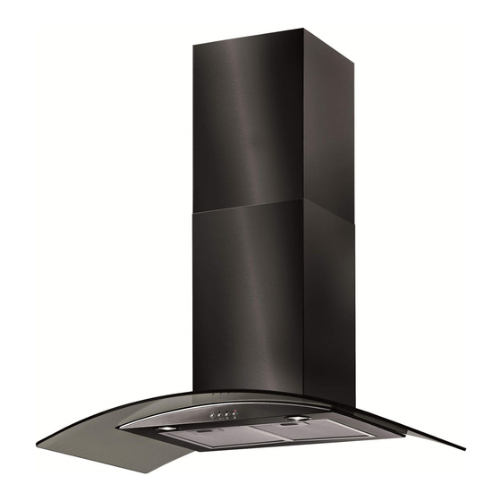
- Page 1 BT9.3GL/BT9.3BGL 90 cm Glass chimney hood waeady...
- Page 2 User Manual for your Baumatic BT9.3GL/BT9.3BGL Cooker Hood 90 cm Glass chimney hood NOTE : This User Instruction Manual contains important information, including safety & installation points, which will enable you to get the most out of your appliance. Please keep it in a safe place so that it is easily available for future reference;...
-
Page 3: Table Of Contents
Contents Page Environmental note MPORTANT SAFETY INFORMATION 5 – 7 pecifications of your cooker hood sing your Baumatic cooker hood 8 - 9 leaning your Baumatic cooker hood The grease filter aintenance Removing and cleaning the grease filter Changing a light bulb... -
Page 4: Environmental Note
NVIRONMENTAL NOTE Note: Before discarding an old appliance, switch off and disconnect it from the power supply. Cut off and render any plug useless. Cut the cable off directly behind the appliance to prevent misuse. This should be undertaken by a competent person. -
Page 5: Important Safety Information
MPORTANT SAFETY INFORMATION Your safet y is of the utmost importance to Baumatic. Please make sure that you read this instruction bookl before attempting to install or use the appliance. If you are unsure of any of the information contained i this booklet, please contact the Baumatic Technical Department. - Page 6 o The edges of the cooker hood are sharp – be mindful of this a you handle your appliance, es pecially during installation and cleaning. DO NOT CLEAN IN BEHIND THE GREASE FILTERS If the room where the cooker hood is to be used contains a fuel burning appliance such as a central heating boiler then its flue must be of the sealed or balanced flue type.
- Page 7 Remember that when in extraction mode, your cooker hood removing air f rom your room. Ensure that proper ventilation measures are being observed. Note that the cooker hood rem oves odours from your kitchen, not steam. Warning - Always en sure that the cooker hood has been disconnected from the power supply before carrying out any wor...
-
Page 8: S Pecifications Of Your Cooker Hood
Congratulations on purchasing a Baumatic Cooker ood! DIMENS IONS: Width (canopy 900 mm Depth (canopy): 500 mm Height (with chimney) 583 mm – 1083 mm DIMENSIONS OF CHIMNEY SECTION: 308 mm x 275 mm Your stainless stee... - Page 9 Make sure that it has been installed by a suitably qualified person, as per the information contained in Baumatic’s installation instructions. Find the control panel, which is located at the front right of the canopy. o There are several buttons on the control panel, which perform separate functions.
-
Page 10: C Leaning Your Baumatic Cooker Hood
Baumatic cooker hood IMPORTANT: BEFORE CLEANING, ALWAYS ENSURE THAT YOU HAVE SWITCHED YOU R COOKER HOOD AT THE OMNI-POLAR SWITCH, SET AT THE WALL FROM THE CABLE. Cleaning o Clean the external parts of your cooker hood with mild liquid deter gent and a new damp cloth. -
Page 11: Maintenance
Maintenance m ving and cleaning the grease filters o First remove the grease filter by pulling down on the handle, and then pull it upwards away from the main body of the cooker hood. o Soak the grease filt ers in hot water and washing up liquid for about an hour. -
Page 12: Changing A Light Bulb
anging a light bulb IMPORTANT: BEFORE ATTEMPTING TO CHANGE A LIGHT BULB, YOU MUS T ENSURE THAT YOU HAVE D ISCONNECTED THE COOKER HOOD FROM YOUR MAINS S UPPLY. o Remove the grease filters (as described on page 11). o Prior to touching the light bul bs ensure that they have cooled down. -
Page 13: Fitting The Carbon Filters
itting the carbon filter If h t e appliance is going to be used in recirculation mode then it is ecessary to fit carbon filters. This will help to absorb unpleasant odours caused by cooking. IMPORTANT: BEFORE ATTEMPTING TO FIT OR REMOVE THE CARBON FILTERS, YOU MUST ENSURE T HAT YOU HAVE DISCONNECTED THE... -
Page 14: I Nstallation
nstallation IMPORTANT: Bef ore installation and usage read all the instructions and make sure that the voltage (V) and the frequency (Hz) indicated on the rating plate are exactly the same as the voltage and frequency in your home. The rating plate can be found behind the grease filters The manufacturer de lines all responsibility in the event of the installer iling to observe all the accident prevention regulations in force,... -
Page 15: Before Beginning Installation
As the colours of the wires in the appliance’s mains lead may correspond with the coloured markings identifying the terminals in your spur box, please proceed as follows: o The blue wire must be connected to the terminal marked “N” (neutral), or coloured black. -
Page 16: Installing Your Cooker Hood
o Rawl plugs are provided to secure the hood to most types of walls and ceilings. However a qualified technician must verify the suitability of the materials, in accordance with the type of wall and ceiling. The wall and ceiling must be strong enough to tak the weight of the hood. - Page 17 2 Position the hood against the wall that you are intending to stall it on and mark the position of the support holes that are be drilled (as shown in the figure below). a) The support screw holes are indicated by figure A in this drawing nd the anchoring screw holes are indicated by figure B.
- Page 18 4) Insert rawl plugs into all of the holes that you have drilled. 5) Fasten the support screws halfway in, leaving them 10 mm out of the wall. ) Hang the hood onto the support crews. 7) Fully tighten the support screws (A) and then screw the anchoring screws (B) through the relevant holes in the cooker hood.
-
Page 19: Connecting To External Ducting
Connecting to external ducting 8) Connect the coupling to the top of the cooker hood, and then connect a 125 mm ducting hose to the coupling (please note that the ducting hose is not supplied with the appliance). o The other end of the ducting ho se should be connected to a discharge outlet that is suitab le for cooking vapours. - Page 20 10) Lift chimney section D upwards until it reaches the ceiling. You must ensure that it is perpendicular to the hood. o Mark the side measurements of both sides of chimney section D on the wall with a pencil and then remove chimney section D. ) Take the fixing bracket (E) and place it between the two pencil ma s rk that you made in step 9.
- Page 21 2) Using an 8 mm drill bit, drill out two holes on the pencil markings at you made in step 11. Insert rawl plugs into the holes and then se a screwdriver to secure the fixing bracket to the wall. o Refit chimney section C to the hood and fix it onto the hood using the two screws that a re supplied.
-
Page 22: Completing The Installation
mpleting the installation you are setting the appliance to recirculation mode, then you should now fit the two carbon filters. See the “Fitting the carbon filters” ection on page 13. he electrical connection must correspond to the electrical requirement oted on the rating plate, which is placed inside the cooker hood. The ppliance should now be connected to the electrical supply. -
Page 23: Troubleshooting
Troubleshooting IMPORTANT: If your cooker hood ap pears not to be operating properly, before contacting the Baumatic Service Department, please refer to the checklist below. My cooker hood will not start. o Check that the hood is connected to the electricity supply o Check that the fan speed control is set correctly. - Page 24 Or any installation other an the one specified by Baumatic Ltd. has been completed. Please refer to the conditions of guarantee that appear on the warranty card that you receive with the appliance when it is delivered.
-
Page 25: C Ontact Details
Republic of Ireland 01- 6266 798 Czech Republic Baumatic CR SPOL. S.R.O. 46215, Librec nited Kingdom The Czech Republic aumatic Ltd., aumatic Buildings, +4204 8357 7200 Bennet Road, eading, Berkshire www.baumatic.cz G2 0QX nited Kingdom Germany Baumatic GMBH ales Telephone... - Page 28 28 28...
Need help?
Do you have a question about the BT9.3BGL and is the answer not in the manual?
Questions and answers