Table of Contents
Advertisement
Quick Links
Advertisement
Table of Contents

Related Manuals for Euphonix CS3000


Summary of Contents for Euphonix CS3000
- Page 1 CS3000 CS2000 Operation Manual Version 3.0 Revision 1...
- Page 2 CS3000, CS2000, MixView, Crescendo, Total Automation, SnapShot Recall, Audio CUBE, Digital Studio Controller, DSC, GainBall and GainCurve are trademarks of Euphonix Inc. ©1996 Euphonix Inc. All rights reserved worldwide. No part of this publication may be reproduced, transmitted, transcribed, stored in a retrieval system, or translated into any language in any form by any means without written permission of Euphonix Inc.
-
Page 3: Table Of Contents
CS2000 I/O Audio Block Diagram (Rev E) ........1 - 25 CS3000 Master Audio Block Diagram (Stereo Outputs) ....1 - 26 CS3000 Master Audio Block Diagram (Aux & Monitor Outputs) 1 - 27 SECTION 2 : GETTING STARTED ......2 - 1 The Screen Display ................ - Page 4 Isolate During SnapShot Recall ............3 - 12 Items NOT Stored as part of SnapShot Recall ......3 - 12 SECTION 4 : TUTORIAL ........4 - 1 Signal Flow Diagram Symbols ............4 - 3 Channel Blocks ..................4 - 4 Euphonix CS3000/2000 Operation Manual...
- Page 5 Mono Insert Point ....................4 - 24 Sound! ........................4 - 24 Exercise 4 Multitrack Routing ............4 - 25 Source ........................4 - 25 Assign ........................4 - 25 Mode ........................4 - 25 Bus Summing Amps ....................4 - 26 Euphonix CS3000/2000 Operation Manual...
- Page 6 Oscillator ....................... 4 - 50 CLIP Indicator Options ................... 4 - 52 D Monitor/Phones ....................4 - 53 Monitor SET Options ................. 4 - 54 Monitor AutoMute ....................4 - 54 Monitor Link ......................4 - 54 Euphonix CS3000/2000 Operation Manual...
- Page 7 Fader Names ..................4 - 70 SECTION 5 : THE PATCHBAY ........ 5 - 1 Half-Normalling ..................5 - 4 The Euphonix Patchbay System ............5 - 5 Patchbay Layout .................. 5 - 6 Channel Patch Unit ....................5 - 7 User Connections ....................
- Page 8 Talkback In/Out (TB Out, TB In) ................5 - 13 Mults ........................5 - 13 Tie-Line Patch Unit ................5 - 14 System Supplied Without Euphonix Patchbays ......5 - 14 SECTION 6 : MOVING FADERS ......6 - 1 Moving Faders (DSC) ................6 - 3 Moving Faders (Channel) ..............
- Page 9 Edit Descriptions ....................7 - 26 Edit Region ..................7 - 26 Manual Timecode entry ..................7 - 26 Using Cue/Locate points ..................7 - 27 On-The-Fly ......................7 - 27 Offline Trim ......................7 - 27 Euphonix CS3000/2000 Operation Manual...
- Page 10 Fast Access to Group Control ............8 - 11 Deleting Groups ................. 8 - 11 Delete an Individual Group ..................8 - 11 Delete All Groups ....................8 - 12 Storage & Recall of Group Data ............8 - 12 Euphonix CS3000/2000 Operation Manual...
- Page 11 Page 2 Numeric Keypad Select Filters ..............9 - 35 Key Inputs ................... 9 - 36 Filters ....................9 - 37 Filters Pre-Compressor/Gate ................. 9 - 37 Filters Only ......................9 - 37 Filter Types..................9 - 38 Euphonix CS3000/2000 Operation Manual...
- Page 12 Pan Bus Masters ....................10 - 16 Bus Kill ........................10 - 16 SECTION 11 : HYPER-SURROUND ......11 - 1 Overview ..................... 11 - 3 Panner Rotary Control Set ..................11 - 3 Panner Assignable Key Set ................... 11 - 3 Euphonix CS3000/2000 Operation Manual...
- Page 13 Rear ....................... A - 8 Outside....................A - 8 Surface ....................A - 8 Model # ....................A - 9 CS3000-2-40 ..................A - 9 CS3000-3-72 ..................A - 9 CS3000-4-104 ..................A - 9 Audio Tower Dimensions ..............A - 10...
- Page 14 Table of Contents This page intentionally left blank Euphonix CS3000/2000 Operation Manual...
-
Page 15: Section 1 : Introduction
Section 1: Introduction INTRODUCTION EUPHONIX MIXING SYSTEMS Euphonix CS3000/2000 Operation Manual 1 - 1... - Page 16 Section 1: Introduction This page intentionally left blank 1 - 2 Euphonix CS3000/2000 Operation Manual...
-
Page 17: System Component
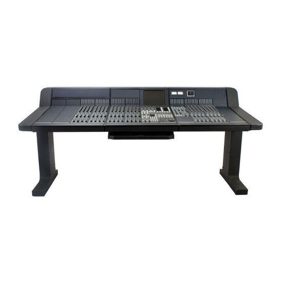
Section 1: Introduction SECTION 1 : INTRODUCTION he Euphonix CS3000 & CS2000 are digitally controlled analog audio mixing systems. The system foundation consists of four component parts: the digital Mix Controller, the Audio Tower, the patchbay, and the support computer. -
Page 18: The Audio Tower
The result is an electronically well-managed audio control system. Since all of the analog audio circuitry is in a remote Tower, the Euphonix Mix Controller is sleek and compact, freeing up valuable control room real estate. The remote location of the... -
Page 19: The Support Computer
All Euphonix systems are compatible so you can track in one city and instantly reconfigure a CS3000/ 2000 on the other side of the globe to exactly match where you left off. -
Page 20: I/O Channel Module
PAN BAL ovld Fader Null indicators EQ•Dyn EQ•Dyn1 Attention key EQ•Dyn2 Attention key Fader Assignment display Lower Fader Block Attention key Motorized Long-Throw AFL/Kill Solo Automated fader Group Master indicator Fader ON (Mute) 1 - 6 Euphonix CS3000/2000 Operation Manual... -
Page 21: Master Module
A7•8 Ext 1 Ext 2 Monitor Source Selection keys Each stereo output has a fader ON key Left Right Stereo Mono and Attention key Stereo Output 1 & 2 Blocks Monitor Mode keys Euphonix CS3000/2000 Operation Manual 1 - 7... -
Page 22: The Dsc
Numeric Keypad 32 Dedicated Keys for use Safe Safe during routing and automation Solo Solo SpinKnob for data entry upper to speed up access time. and list scroll Enter lower Dedicated Keys 1 - 8 Euphonix CS3000/2000 Operation Manual... -
Page 23: This Manual
ES108A Dynamics unit. Section 10 describes the operation of the software- integrated Euphonix Audio Cube and various available multi-format bus options and functions. The fastest way to become a fully-functional Euphonix user is to go through the Tutorial section while sitting in front of the console. - Page 24 Note: Throughout this manual, keys to be pressed are represented toggle [F4] through the options to choose either PLF (Post Lower by bold type and brackets as shown in this example: [Esc]. Fader) or PUF (Post Upper Fader). 1 - 10 Euphonix CS3000/2000 Operation Manual...
-
Page 25: The Dsc (Digital Studio Control) Module
The use of this technology enables the Euphonix to build on traditional console interfaces and at the same time introduces a new and exciting way of controlling an entire studio as an integrated system. -
Page 26: Master Control Panel
EQ, and snapshot functions will operate normally. Numeric keypad, SpinKnob, +/– keys, and other keys in this area are used to navi- gate through SmartDisplay menus and perform menu- specific functions. Enter 1 - 12 Euphonix CS3000/2000 Operation Manual... -
Page 27: Dedicated Keys
Routing Keys. operate only in M1, M2, L1, L2, L3, L4 allow Template and fast source selection. upper Punch menus. ST1, ST2, and DIR allow fast access when assigning faders to their sources. lower Euphonix CS3000/2000 Operation Manual 1 - 13... -
Page 28: Using The Dedicated Keys
W out Mutes, and Aux ABCD Selects Trim mode when Write In, Write Out, Write running automation system Through automation. See the Automation section for a full description of the key functions labelled above. 1 - 14 Euphonix CS3000/2000 Operation Manual... -
Page 29: Assignable Rotary Control Set
More detailed examples are given in the following pages. Automation Status Indication: Iso, Dynamic, Trim (if applicable) i d t i d t i d t i d t Automation Punch key Assignable for the assignable switch Function key Euphonix CS3000/2000 Operation Manual 1 - 15... -
Page 30: Mode Select Keys
Selects Audio Cube control mode Aux Send control mode Bus Master control mode for auxes or multi-format pans Selects ES108A Selects Audio Cube Not yet Dynamics/Filters Multi-Format Bus implemented control mode Panning screens & controls 1 - 16 Euphonix CS3000/2000 Operation Manual... -
Page 31: Equalizers
Pg 1 accesses EQ1 and Pg 2 i d t i d t i d t i d t accesses EQ2 Pg 1 Pg 2 Pg 3 Pg 4 List EQ key accesses the EQ screen Chan Assign Master Euphonix CS3000/2000 Operation Manual 1 - 17... -
Page 32: Dynamics
Page 2 key switches to the Pg 1 Pg 2 Pg 3 Pg 4 List Filters screen; Page 1 back to the Compress/Gate screen Chan Assign Master Selects the Dynamics screen 1 - 18 Euphonix CS3000/2000 Operation Manual... -
Page 33: Assignable Keys
Assignable Key is used to tell the operator what the function of the key is. Its function depends on what mode or page is currently selected. Software-defined controls enable Euphonix to add new features to any of the control sections of the console. -
Page 34: Channel/Route Select Keys
The hidden-til-lit multitrack indicators on the faders of a standard 12-bus console will show appropriate numbering for the buses (1-12 for upper and lower faders instead of 1-24 for upper faders only). 1 - 20 Euphonix CS3000/2000 Operation Manual... -
Page 35: Track Assign Keys
Play, Record, Stop, Forward, Rewind, Cycle, Shuttle, Locate to Cue, Next Cue, Last Cue, and RollBack. The Euphonix VTM is effectively an internal timecode generator. When the DSC Mstr Ctrl and T/C Slave keys are off, then internal timecode can be generated. -
Page 36: Assignable Moving Faders
(Iso, Dyn, Trim) Mute Punch Key Safe Safe Solo Solo Mute Note: The Assignable Moving Faders currently only work in Absolute mode. Future software releases will enable the use of other automa- tion modes. 1 - 22 Euphonix CS3000/2000 Operation Manual... -
Page 37: Cs3000D I/O Block Diagram (Rev F)
Section 1: Introduction CS3000D I/O Block Diagram (Rev F) Euphonix CS3000/2000 Operation Manual 1 - 23... -
Page 38: Cs3000P/B I/O Block Diagram (Rev F)
Section 1: Introduction CS3000P/B I/O Block Diagram (Rev F) 1 - 24 Euphonix CS3000/2000 Operation Manual... -
Page 39: Cs2000 I/O Audio Block Diagram (Rev E)
Section 1: Introduction CS2000 I/O Audio Block Diagram (Rev E) Euphonix CS3000/2000 Operation Manual 1 - 25... -
Page 40: Cs3000 Master Audio Block Diagram (Stereo Outputs)
Section 1: Introduction CS3000 Master Audio Block Diagram (Stereo Outputs) STEREO 1 BUS ST1L(A) ST1R(A) Stereo pre-fader ST1L(B) insert relays linked together Pre-fader feed to ST1 C ST1 feed to Mon Select & Meters ST1R(B) ST1L(C) ST1L(INS) External Stereo Comp... -
Page 41: Cs3000 Master Audio Block Diagram (Aux & Monitor Outputs)
Section 1: Introduction CS3000 Master Audio Block Diagram (Aux & Monitor Outputs) Aux Bus Talkback Select and Aux Masters AUX 1 1 - 8 Feeds to Buses Sine AUX 2 EXT TB IN AUX 3 AUX 4 TB OUT AUX 5... - Page 42 Section 1: Introduction This page intentionally left blank 1 - 28 Euphonix CS3000/2000 Operation Manual...
-
Page 43: Section 2 : Getting Started
Section 2: Getting Started GETTING STARTED EUPHONIX MIXING SYSTEMS Euphonix CS3000/2000 Operation Manual 2 - 1... - Page 44 Section 2: Getting Started This page intentionally left blank 2 - 2 Euphonix CS3000/2000 Operation Manual...
-
Page 45: The Screen Display
659 1.3K 2.6K 5.3K 11K Startup Screen When you first start up the CS3000/2000 you will notice the screen below. The thin window bar at the top of any window list is highlighted in blue indicating when it is active. According to this screen, there is no title or mix currently loaded into the console. -
Page 46: Status Bar
Gray <90 Passes Last Recalled Snapshot Red >90 Passes (includes Automated SnapShots) During RECORD Start Time Position # of Moves (of first punch-in) Total number of moves recorded End Time Position (of last move) 2 - 4 Euphonix CS3000/2000 Operation Manual... -
Page 47: The Smartdisplay And Master Control Panel
As with any computer-based system, regular and complete backups are essential to protect your system files. Euphonix CS3000/2000 Operation Manual 2 - 5... -
Page 48: File Hierarchy
Mounting Disks The Euphonix support computer can address a SCSI drive attached to it for storage. Normally, all computer hard disks (C: drive, etc.) appear in the Drive list window when accessed. If you insert a DOS (IBM-compatible) formatted removable cartridge into the D: drive, the list does not show the disk immedi- ately. -
Page 49: System Data Organization
Section 2: Getting Started System Data Organization Euphonix CS3000/2000 Operation Manual 2 - 7... -
Page 50: List Selection
Although you can operate the system without saving, it is so easy to save and retrieve your work that it makes no sense to operate without having named a project and title into which your valuable mixes and snapshots can be stored. 2 - 8 Euphonix CS3000/2000 Operation Manual... -
Page 51: New Project
QWERTY keyboard. You can type in up to 4 lines of remarks in the Comments field. Pressing [Tab] again gets you back to the Project list. You can return to the Comments field at any time to update your comments. Euphonix CS3000/2000 Operation Manual 2 - 9... -
Page 52: Rename Project
If you want to copy the entire project to the same drive, press [F4] ([OK]). If you want to copy to a different drive, select the drive in the Disk list using the SpinKnob or DSC [+]/[–] keys and then press [F4]. 2 - 10 Euphonix CS3000/2000 Operation Manual... -
Page 53: Titles
An example of a typical Title window, showing the titles contained in a project is shown below. (See “Titles and Files” in the Appendix section for a breakout of all system files found on the CS3000 system hard disk.) Title Window:... -
Page 54: Title Hierarchy
Load? Save? Utils A window will appear on the screen display allowing you to name your new title. Enter the name of the title by typing in the keyboard and then press [Enter]. 2 - 12 Euphonix CS3000/2000 Operation Manual... -
Page 55: Title Comments
Audio Cube - Bus allocations, bus names, bus linking and inserts, and I/O switch settings. Dynamics - Assignments of CS3000/2000 channels to ES108A channels. MX464 Master Expander - GPI relay assignments. Mixes - Up to 200 mixes can be stored within a title. -
Page 56: Title Utilities Menu
Copy, you will be prompted to select the destination disk and project folder for the copy in exactly the same way as you had to select the disk for copying a project. 2 - 14 Euphonix CS3000/2000 Operation Manual... -
Page 57: Backing Up Title Onto A Removable Cartridge
End times in relation to the Film o/s - Sets a TC offset number which is applied to film’s incoming Head and Tail of the title. feet|frames reference in order to sync your mixes to film. Euphonix CS3000/2000 Operation Manual 2 - 15... -
Page 58: Mixes
Mixes contain all automation data. The file management menus for mixes are Mixes similar to those for projects and titles; you will find Utility menus allowing mixes to be renamed, copied, and deleted. (See the Automation section for more about mixing.) 2 - 16 Euphonix CS3000/2000 Operation Manual... -
Page 59: Section 3 : Snapshot Recall
Section 3: SnapShot Recall SNAPSHOT RECALL EUPHONIX MIXING SYSTEMS Euphonix CS3000/2000 Operation Manual 3 - 1... - Page 60 Section 3: SnapShot Recall This page intentionally left blank 3 - 2 Euphonix CS3000/2000 Operation Manual...
-
Page 61: The Master Control Panel
Main menu shown in the Master Control Panel’s SmartDisplay below: Pass Pass Grps Mtrs Ctrl Setup Snap System Grps Returns you step by step back up the menu Enter hierarchy Master Control Panel on DSC Euphonix CS3000/2000 Operation Manual 3 - 3... -
Page 62: Interactive Screen Display
DSC SnapShot keys or the DSC [+]/[–] keys is a destructive process that Mode key “clears” all console settings by loading another SnapShot. For non-destructive SnapShot list scrolling, use the SpinKnob to highlight a stored SnapShot location on the screen and press [F4]. 3 - 4 Euphonix CS3000/2000 Operation Manual... -
Page 63: Snapshot Mode
F4. The only difference with these keys is that each time you press the key, the SnapShot memory resets the console without having to press F4. This is invaluable for sequential SnapShot recall in live performance work. Enter Euphonix CS3000/2000 Operation Manual 3 - 5... -
Page 64: Storing (Sto) A Snapshot
Momentary display: ...SnapShot STORED Then: **SS=16 The current desk has now been stored to 16. Note that the left number now indicates that 16 is the active SnapShot and [F3] has returned to RCL. 3 - 6 Euphonix CS3000/2000 Operation Manual... -
Page 65: Rename A Snapshot
Notice that the number following the “SS” updates to show that SnapShot 10 SnapShot location #10. is now active in channel 5. Press [F1] to return to Global SnapShot mode. Euphonix CS3000/2000 Operation Manual 3 - 7... -
Page 66: Nulling Controls
Null mode. When you move the faders away from the null they will automati- cally activate. In some instances, nulling does not operate as described above when used Motorized Faders with motorized faders. See the motorized faders portion of the Automation Section for more information. 3 - 8 Euphonix CS3000/2000 Operation Manual... -
Page 67: Auto Null Selected (A)
Fader has been moved by the green to the fader. All indicators so RED indicator indicator. go out. shows direction the fader has to be moved to reach the null point. Fader is disconnected from audio. Euphonix CS3000/2000 Operation Manual 3 - 9... -
Page 68: Zeroing The Desk
Pg 3 Pg 4 Faders Faders Store Store Match Pg 1 Pg 2 Pg 3 Pg 4 Null Mode Preset Preset Studio Studio Macro Macro Snap Snap Select Select Cnfg Cnfg Shot Shot 3 - 10 Euphonix CS3000/2000 Operation Manual... -
Page 69: Auto-Backup
Auto-Backup console, you might lose changes made since you last saved your settings. However, the Euphonix has a built-in automatic backup system which stores the entire console to battery-backed RAM on a regular basis. You can set the frequency of this auto-backup procedure from the Console Backup menu. If you ever need to recall the backup SnapShot it is also done via this menu. -
Page 70: Isolate During Snapshot Recall
Monitor Levels, KillSolo/Afl, Intercancel Solo, Dim Level, Mono Level, Monitor SnapShot Recall Set On/Off, T/B On/Off, Monitor Link, Clip Level & Monitor Left/Right selec- tion. Groups are not stored with a SnapShot, but with each mix and with the title. 3 - 12 Euphonix CS3000/2000 Operation Manual... -
Page 71: Section 4 : Tutorial
Section 4: Tutorial TUTORIAL EUPHONIX MIXING SYSTEMS Euphonix CS3000/2000 Operation Manual 4 - 1... - Page 72 Section 4: Tutorial This page intentionally left blank 4 - 2 Euphonix CS3000/2000 Operation Manual...
-
Page 73: Signal Flow Diagram Symbols
1 Bus Summing Amp - Takes the multitrack bus associated with that channel Summing and amplifies it to line level. Busing - Each channel strip can access 2 sets of Stereo buses, 24 Multitrack buses, 8 Aux send buses, Stereo Solo (PFL/AFL) bus. Euphonix CS3000/2000 Operation Manual 4 - 3... -
Page 74: Channel Blocks
12 from upper and lower faders depending on Audio Tower jumper configuration - see technical manual for details), Direct Outputs (Dirs 1 & 2), and Aux buses 1 - 8 (from the aux blocks only). 4 - 4 Euphonix CS3000/2000 Operation Manual... -
Page 75: Exercise 1 Stereo Source/Stereo Fader/Stereo Bus/Monitor
[ST2] as the destination. ST2 is a completely separate stereo bus with its own master fader, insert and patch points. Re-select only ST1. The signal path we have set up now looks like this: STEREO 1 BUS Euphonix CS3000/2000 Operation Manual 4 - 5... -
Page 76: Mode
We will show how to set the meter modes globally for all channel I/O meters and then for individual channels via the SmartDisplay Meter menus. We will also set the meters for the Master Module. 4 - 6 Euphonix CS3000/2000 Operation Manual... -
Page 77: Metering Presets
Starting with unconfigured meters, attention is initially directed to the right channel meter as indicated by the arrow between Aud and OFF shown above. Press [F2] to direct attention to the left meter: ovld 1CH->Aud->OFF Aud:OFF Euphonix CS3000/2000 Operation Manual 4 - 7... -
Page 78: Master Module Meter Selection
“unity gain”. Press the ST1 [ON] button and bring the master fader to the 8 (unity gain) mark. Assuming you have successfully setup the Master meters and your audio source is playing, you should now see the audio levels on ST1 output. 4 - 8 Euphonix CS3000/2000 Operation Manual... -
Page 79: Save That Console
Section 4: Tutorial The CS3000/2000 is equipped with 3 monitor speaker outputs labelled A, B & Monitor A monitor C. Each monitor section has its own Level control, DIM, and SET keys. We will Source assume there are amplified speakers connected to the “A” Output. We will Selection listen to ST1 through Monitor A. -
Page 80: Universal Input Amplifiers (Uias) M1 & M2
[F2] below the SmartDisplay. If the multitrack return is Multitrack Return normalled into M2 then [F2] acts as a bus/tape switch. 16M2–> Bus/ 4.0dB Cnfg From Bus Summing Amp Acts as bus/tape switch 4 - 10 Euphonix CS3000/2000 Operation Manual... -
Page 81: Equalizers
Also the source M1 is shown in the DSC screen and SmartDisplay: The EQ1 and EQ2 keys are located in the lower fader block for 16E1–> 0.0dB –>M1>- convenience. They are not necessarily part of the lower fader signal path. Euphonix CS3000/2000 Operation Manual 4 - 11... -
Page 82: Stereo Linking Eqs
[*ST] key, EQ2’s curve is copied into EQ1. STEREO 1 BUS 4 Band EQ Signal path after Stereo Links stereo linking EQs 4 Band EQ 4 - 12 Euphonix CS3000/2000 Operation Manual... -
Page 83: Adjusting Eq With The Dsc
EQ. The list below shows the default values: Band Frequency Note High 10.5kHz High Mid 2.64kHz 0.51 Lower Mid 330Hz 0.51 82.4Hz EQ 1 (M1) Default values with no routing selected 659 1.3K 2.6K 5.3K 11K Euphonix CS3000/2000 Operation Manual 4 - 13... -
Page 84: Eq Screen Display
When you select a source for the EQ (M1, M2, L1, L2, L3, L4), that source appears in the EQ graph info bar. If the source is selected but the EQ is by- passed (“out”), the source appears in parentheses as seen in the diagram above. 4 - 14 Euphonix CS3000/2000 Operation Manual... -
Page 85: Eq Curves
@2.64kHz. With the Q value at 0.51, the EQ graph will look like this: EQ 1 Adjusting Upper-Mid Gain +12dB @ 2.64kHz 659 1.3K 2.6K 5.3K 11K The SmartDisplay shows the parameter values changing in real time as you adjust the EQ. Euphonix CS3000/2000 Operation Manual 4 - 15... -
Page 86: Q Range
SmartDisplay in Musical Note mode 16E1–> –>M1>- The range of the Q on the mid bands is variable from 0.32 at its broadest to Q Range 11.6 at its narrowest. The default Q value is 0.51. 4 - 16 Euphonix CS3000/2000 Operation Manual... -
Page 87: Adjusting The Eq Using Keypad
F1 asking where to copy the EQ values. Press any EQ attention key and the whole EQ curve will be copied into that EQ. ????<–16EQ1 Gs/Fs/Qs The SmartDisplay is showing you that the Gains, the Frequencies and the Qs will be copied across. Euphonix CS3000/2000 Operation Manual 4 - 17... -
Page 88: Cascading 2 Eqs To Produce An 8-Band Eq
Insert Points Unlike conventional consoles which provide 1 fixed insert point, the CS3000/ 2000 allows you to build insert points into the signal path when and where they are required. Each channel can have up to 3 insert points. This could provide a pair of insert points for a stereo fader and the third insert point could be used for a mono fader. -
Page 89: Exercise 2 Stereo Inserts Into Audio Path
OUT1 Press [Esc] once to return to the Output menu and then F3 to select the Source menu for Output 2. Select [M2] as the source for Output 2. Dedicated Source Assign keys Euphonix CS3000/2000 Operation Manual 4 - 19... -
Page 90: Insert Diagrams, Pre- & Post-Eq
To bypass the insert point, select M1 and M2 rather than L1 & L2 as the sources for both the EQ and the fader (this can be done with one button press using the SnapShot Recall system). This concludes Exercise 2. 4 - 20 Euphonix CS3000/2000 Operation Manual... -
Page 91: Exercise 3 Multitrack Monitoring
If no keys are pressed after F1, the copy function will copied with block copy. They must time out and the SmartDisplay will revert to the Channel/Block menu. be copied using a channel’s attention key and subsequent ASGN menu item. Euphonix CS3000/2000 Operation Manual 4 - 21... -
Page 92: Clear/Copy Objects
Sure ? [No] Remember that when you recall the default Snapshot, you lose the current settings on the desk. If you don’t want to lose the settings, save them to a SnapShot location first. 4 - 22 Euphonix CS3000/2000 Operation Manual... -
Page 93: Construct Signal Path
Slct onln Slct As a convenient alternative, you can use the DSC’s Channel/Route Select keys onln to direct attention and carry out your copy operations. Slct Solo shft onln Route Euphonix CS3000/2000 Operation Manual 4 - 23... -
Page 94: Add Eq
In systems outfitted with 2 dynamics processors per channel, the insert send/return pairs Out1/L1 and Out2/L2 are usually normalled through the ES108A processors. The normalling is done at the patchbay. 4 - 24 Euphonix CS3000/2000 Operation Manual... -
Page 95: Exercise 4 Multitrack Routing
“Mono Pan”. If you have a mono source and you want to assign it to only one bus or Euphonix CS3000/2000 Operation Manual 4 - 25... - Page 96 LED remains lit (for both M1 and MT assignments) along with the B LED (MT for the CS2000). Indicates MT selected as Out3 source Out3, M1 designation Out 1 Out 2 Out 3 4 - 26 Euphonix CS3000/2000 Operation Manual...
-
Page 97: L4 Bus/Tape Switching
Setup”, for example. Now whenever you start a mix, you won’t need to reconstruct this setup from scratch. Just recall your “Basic Mix Setup” snap- shot (channel 1 is also set for tracking in this snapshot). Euphonix CS3000/2000 Operation Manual 4 - 27... -
Page 98: Bus Summing Amps
EQ1 & EQ2 to be M1 & M2 respectively. Now route the upper fader to a pair of multitrack buses. The signal path will look like this: Multitrack Buses 4 Band EQ Stereo Links even 4 Band EQ This concludes Exercise 4. 4 - 28 Euphonix CS3000/2000 Operation Manual... -
Page 99: Auxiliary Sends
There are eight (8) auxiliary send buses which have their master gain controls Auxiliary Sends labelled A1 to A8 in the upper part of the CS3000/2000 Master Module. Each of the eight masters has a gain control and an on/off key. - Page 100 Aux sends A and B: AUX BUS 1 - 8 Aux A Mono Independent Post Lower Fader Aux B Link STEREO 1 BUS 4 Band EQ Line Input 4 This concludes Exercise 5. 4 - 30 Euphonix CS3000/2000 Operation Manual...
-
Page 101: Fader Source Tracking
3. As you select or deselect other fader sources (M1, L3, etc.), notice that the Aux source indicator lights track the Lower fader source display. As mentioned earlier, control of aux send muting and pre/Post routing is still possible from the top-level Aux Status menu. Euphonix CS3000/2000 Operation Manual 4 - 31... -
Page 102: Configuring Aux Send Modes
L/P? The small square indicates that the 0dB lock is engaged. Configuring Aux CS3000/2000 aux sends can be configured many different ways for different applications. It is essential that the aux Modes be set before Source and Send Modes Assign primarily because under certain conditions, aux mode selection will clear source and assign selections. -
Page 103: Exercise 7
A: 16A-> To change to stereo linked mode, press the [*ST] key and then [F3] (Yes): Stereo Aux ? [No] 16AB-> Stereo Ind? Euphonix CS3000/2000 Operation Manual 4 - 33... -
Page 104: Mono Pan Center Locked Mode
SIDE NOTE: Press [F2] to select Mono mode: This mode is rarely used and should not be confused with the 16AB-> Mono - - - Ind? similarly displayed Mono Independent mode. 4 - 34 Euphonix CS3000/2000 Operation Manual... -
Page 105: Exercise 8
[Esc] key to backup to the Aux Config menu and/or press the aux send A block attention key to view the Aux Status menu: Aux Config Menu 16AB-> * SRC MODE ASGN Aux Status menu 16AB-> * ON This concludes Exercise 8. Euphonix CS3000/2000 Operation Manual 4 - 35... -
Page 106: Stereo Center Locked Mode
(A or B) is replaced. The other half of the stereo block is cleared back to Mono Ind mode with no SRC or ASGN settings. 4 - 36 Euphonix CS3000/2000 Operation Manual... -
Page 107: Solo Afl And Pfl
The solo signal replaces the Active normal monitor signal. The main stereo buses are NOT interrupted. The Solo Level knob (not the MON knob) controls the signal’s level. Controls AFL/PFL Level Euphonix CS3000/2000 Operation Manual 4 - 37... -
Page 108: Kill Solo Mode (Solo In Place)
AFL/PFL bus and out via the Solo level control. PFL can be in mono or stereo; the fader mode determines which. PFL will operate in the same mode that the AFL button is in (i.e., I/C or All. There is no such thing as Kill solo for PFL). 4 - 38 Euphonix CS3000/2000 Operation Manual... -
Page 109: Direct Outputs
If you press the channel block attention key you will notice that the Direct Via Channel Menus Outputs (DIRs) can also be assigned from here. This allows custom configura- tions to be made. The easiest way to understand this is by way of example. Euphonix CS3000/2000 Operation Manual 4 - 39... - Page 110 UFR Post-Upper Fader Right LFL Post-Lower Fader Left LFR Post-Lower Fader Right Pressing [F2] toggles the menu between DIR1 and DIR2 selection: 16CH–> DIR1 OUT: 16CH–> DIR2 OUT: Exactly the same sources are available for DIR2. 4 - 40 Euphonix CS3000/2000 Operation Manual...
-
Page 111: The Combiner
The Combiner’s output is a mono sum of the selected sources. Its output can then be fed to one or both of the DIRs by selecting CMB as a source in the DIR menu. 16CH–> DIR1 OUT: Euphonix CS3000/2000 Operation Manual 4 - 41... -
Page 112: Combiner/Dir Experiments
If you have equalized M1 & M2 the Combiner will be fed post EQ. Press [Esc] once to invoke the Route menu. Press [F3] to select the DIR 1 menu: 16CH–> DIR1 OUT: 4 - 42 Euphonix CS3000/2000 Operation Manual... - Page 113 Next, press the channels EQ1 attention key and select M1 as its source using the DSC Dedicated Assign keys. Lower Fader Source, Assign, Source the lower fader from M1, assign it to ST1 and put it in Mono Pan Mode mode. Euphonix CS3000/2000 Operation Manual 4 - 43...
- Page 114 4 Band EQ Note also that you still have M2 free for an additional input, with EQ, to the stereo buses via the upper fader! The versatile architecture of the Euphonix console makes this type of routing flexibility possible. Example 3 - Feed a microphone signal to the DIR2 output and thus the multitrack input without using a fader.
- Page 115 Multitrack Machine Line Input 4 STEREO 1 BUS OUT3 Line Output 3 Effects Device Line Input 3 4 Band EQ Multitrack & OUT1 Stereo Buses Line Output 1 Effects Device Line Input 1 Euphonix CS3000/2000 Operation Manual 4 - 45...
-
Page 116: Master Module Signal Flow Options
The signal flow for Stereo 1 outputs is as follows: STEREO 1 BUS ST1L(A) ST1R(A) Stereo ST1L(B) pre-fader insert relays linked together Pre-fader feed to ST1 C (Left & Right) ST1R(B) ST1L(INS) ST1L(C) External Stereo Comp ST1R(INS) ST1R(C) 4 - 46 Euphonix CS3000/2000 Operation Manual... -
Page 117: Switching The Stereo Insert Point
(i.e., the left channel output is 0.25dB lower than the right channel). mS1-> -0.25dB – – This puts a gain offset on the main stereo output. Except in special cases, this setting should generally be left at 0.00dB, without any offset. Euphonix CS3000/2000 Operation Manual 4 - 47... -
Page 118: External Monitor Inputs
This facility is very useful for post work as two sets of three stereo stems can be simultaneously monitored as a 1:1 mix (i.e., feed off-tape stereo music into EXT1A, effects to EXT1B and dialog into EXT1C). 4 - 48 Euphonix CS3000/2000 Operation Manual... - Page 119 ST2R Buffer One of two External Input EXT1 Selector Selectors feed to B & C Monitors SIDE NOTE: Third-party switching devices can be integrated with the Euphonix system to provide true PEC/direct switching. Euphonix CS3000/2000 Operation Manual 4 - 49...
-
Page 120: Talkback
92, of the Master patchbay (page 5-12). The talkback mic plugs into the XLR input under the Mix Controller and is selected by pressing [F4]. Oscillator From the Talkback menu, press [F4] (OSC): Talkback Menu mTB–> ASGN Oscillator Menu mTB–> FREQ LEVEL 4 - 50 Euphonix CS3000/2000 Operation Manual... - Page 121 0.0dB The SpinKnob selects the level and F4 toggles the oscillator on and off. Again, the [+]/[–] keys can be also used to change the level. Range is 20dB, where 0dB = +4dBu. Euphonix CS3000/2000 Operation Manual 4 - 51...
-
Page 122: Clip Indicator Options
Press [F4] (…): … METER CLIP Pressing [F1] (METER) allows the Master meters to be set. These options were covered earlier in this section and the options available are detailed in Appen- dix 9. 4 - 52 Euphonix CS3000/2000 Operation Manual... -
Page 123: D Monitor/Phones
Ext2 Cpre On a CS3000, [F2], [F3], and [F4] toggle the feed from the three Monitor selectors, with only Ext2C fed prior to the D Monitor Gain control. You can select any combination of Solo, Ext 2C or Cpre to the phones. On a CS2000, you can select any combination of Mon A, B or C to the phones. -
Page 124: Monitor Set Options
Now both Monitor B and C are controlled from Monitor B, so you have a single level control for each of the B and C outputs. You will notice that both B and C 4 - 54 Euphonix CS3000/2000 Operation Manual... -
Page 125: Monitor Combinations And Examples
4-channel sound, as would be heard in a theater. The Dolby Matrix includes switching to allow you to listen to the encoded stereo signal and the discrete 4-channel signal prior to the decoder. Euphonix CS3000/2000 Operation Manual 4 - 55... -
Page 126: Film 4-Track Dolby Monitoring Diagram
A & B Mon Link. LnkB selected in Monitor A's EUPHONIX Menu. CONSOLE B Left EXT2A L EXT2 A Power Center & Surround B Right EXT2A R MON B Mon B Controls both A & B 4 - 56 Euphonix CS3000/2000 Operation Manual... -
Page 127: Film 5.1 Monitoring Diagram
EXT1A (R) Mon C Controls both A & B C Left Power C Right MON C Screen B Left Power EUPHONIX B Right CONSOLE MON B A Left Power A Right MON A Euphonix CS3000/2000 Operation Manual 4 - 57... -
Page 128: M/S (Sum & Difference) Modes
L2 gains. This may require an external mic preamp to get the L1 and L2 gains hot enough. In both these examples you can use L3 and L4 instead of L1 and L2 if you wish. 4 - 58 Euphonix CS3000/2000 Operation Manual... -
Page 129: M/S Channel Operation Block Diagram
Right = M - S = 2B = (A+B) - (A-B) Phase Reverse Switched In -(A-B ) = -A+B Fader Source Stereo 1 Bus Select (M Mono) Line In 1 Mode 7: Stereo Line In 2 Euphonix CS3000/2000 Operation Manual 4 - 59... -
Page 130: Midi Machine Control
Euphonix Installation and Service Manual for configuration info. The Euphonix TT007 Machine Control unit, included with the CS3000, also allows CS series consoles to serially control outboard audio and video tape machines. See your Euphonix dealer for more info on the TT007. - Page 131 RollBack allows the user to roll the tape back a determined amount from the current position. PreRoll is a user-definable amount of time that is added to any Locate, Cycle, or RollBack. Auto The Auto function is currently unsupported. Auto Euphonix CS3000/2000 Operation Manual 4 - 61...
-
Page 132: Locate Menu System
[Mstr Ctrl] back on when you want to use MMC again. Once a position has been located using the Enter key, the timecode position is remembered so that pressing the [Loc] key twice at any time locates to the last recalled position. 4 - 62 Euphonix CS3000/2000 Operation Manual... -
Page 133: Cue List And Menu
Tail are shown in the Pass Control screen cue window as well. These points are edited in the Title Setup menu: Setup Snap System Grps New? Load? Save? Utils ReNm? Del? Copy? Setup File F-Link MIDI Disk Project Title T/C Display hh:mm:ss Euphonix CS3000/2000 Operation Manual 4 - 63... -
Page 134: Cue Points
Ctrl Slave generator Storing & Locating to In the Euphonix Cue System, there are several sources of cue points for Cues locating. They are: 1. Locate to a single timecode point entered manually 2. Locate using the shuttle wheel (SpinKnob in Shuttle mode) 3. -
Page 135: Locating To The Head/Tail
“on the fly” while in Play. As you enter or capture timecode values into the Cue list, you will see them displayed sequen- tially in the list on the DSC screen. Euphonix CS3000/2000 Operation Manual 4 - 65... -
Page 136: Capture Cues "On The Fly
SmartDisplay menu. You can get straight to the Cue List menu from any menu by pressing the DSC [Loc] key once followed by [F1] (down arrow): Locate Menu 00:00:00.00 Mark Cue List Menu Cycle Head Edit 4 - 66 Euphonix CS3000/2000 Operation Manual... -
Page 137: Next Cue/Last Cue
DSC Numeric keys to be added/subtracted from the current timecode Change timecode value and then pressing [Enter]. a frame at a time 4. Press [F4] (Now) to capture the current status bar timecode window value to the selected cue point. Euphonix CS3000/2000 Operation Manual 4 - 67... -
Page 138: Assigning Custom Cue Names
The Cue list is saved with the title (See the Getting Started section). If you Saving the Cue List load another title before saving the current one, any changes you made to the Cue list will be lost. 4 - 68 Euphonix CS3000/2000 Operation Manual... -
Page 139: Rollback And Preroll
“Head” (F2) automatically inputs Cue list the title’s Head timecode value; “Cue” (F3) inputs the location of the cue currently highlighted in the Cue list; “Now” (F4) inputs the timecode location Euphonix CS3000/2000 Operation Manual 4 - 69... -
Page 140: Locating To Start (Lts) Function
Whenever this fader is the active fader, its name will appear in the status bar. The track list is saved with the title. The fader names also appear above each channel on the Mix Controller if your console is outfitted with the Euphonix CleaR displays option. -
Page 141: Section 5 : The Patchbay
Section 5: The Patchbay THE PATCHBAY EUPHONIX MIXING SYSTEMS Euphonix CS3000/2000 Operation Manual 5 - 1... - Page 142 Section 5: The Patchbay This page intentionally left blank 5 - 2 Euphonix CS3000/2000 Operation Manual...
- Page 143 Section 5: The Patchbay SECTION 5 : THE PATCHBAY he standard Euphonix patchbay is made up of fully connectorized patch units. Each unit contains two rows of 48 jacks with the upper row half- normalled to the lower row, and takes up 1 unit of 19” rack space (1.75”...
-
Page 144: Half-Normalling
Lower Jack Cold (Input) Plug takes signal from the output without breaking the feed to the lower socket. Plug feeds a source into the lower jack's input and disconnects the upper jack feed. 5 - 4 Euphonix CS3000/2000 Operation Manual... -
Page 145: The Euphonix Patchbay System
Patchbay System perspective of system modularity. The Euphonix patchbay system is designed for convenient expansion when adding more channels of audio to the console. As already mentioned, one Audio Tower can accommodate up to 28 channels (56 faders). -
Page 146: Patchbay Layout
Knowing all of this, you should easily find the appropriate jack on the patchbay. Note that there are two Dir2 patch points per channel. These are mults (parallel splits) of the same Dir2 output with independent user connections at the rear of the patchbay. 5 - 6 Euphonix CS3000/2000 Operation Manual... -
Page 147: Channel Patch Unit
This is not a user connection. The 6 Elco 38 connectors are the user connections into and out of the system. Each connector represents one colored column as described earlier. In a basic Euphonix system, all 6 of these connectors are available for user connections. However, some of these Elco 38... -
Page 148: Channel Inputs And Outputs
Section 5: The Patchbay One of the great features of the Euphonix system is that there Channel Inputs are many inputs and outputs for each channel, and each fader and Outputs can source or route to any combination of them. This means... -
Page 149: Normalling The Multitrack Returns
See the ES108A Dynamics Installation and Service Manual for wiring configu- ration diagrams for various Euphonix mixing systems. Audio CUBE cabling is shipped from the Euphonix factory in one of the follow- ing configurations: STEREO 1 BUS... -
Page 150: Normalling The Audio Cube
Both the Dir1 and Dir2 pins are populated. Some systems (depending on the number of channels) are a combination of 1- per-channel and 2-per-channel cabling. See the Audio CUBE Installation and Service Manual for wiring configuration diagrams for various Euphonix mixing systems. 5 - 10... -
Page 151: Master Patch Unit
TO AUDIO MAINFRAME USER ST2 USER MON A,B,C TB USER ST1 USER AUX 1 - 8 USER EXT1/EXT2 Zinc Gold EUPHONIX P/N 950-01097 MASTER PATCHBAY Stereo External ST1 Bus Out ST2 Bus Out Aux Bus Out Monitor Out Stereo Inputs JACK GND The 90-way Elco at the far left is the Tower interface. -
Page 152: Master Inputs And Outputs
The submixer is capable of summing up to 6 separate stereo sources, via the EXTernal inputs, down to one stereo output (Monitor Output) via a level control (which gives unity gain when fully turned up). 5 - 12 Euphonix CS3000/2000 Operation Manual... -
Page 153: Monitor Outputs Continued
AUX, Multitrack, and Main Stereo Output buses when the Talkback ON key is pressed in the Master section of the Mix Control- ler. Mults Two mults are provided. Jacks 45-48 are paralleled together as are jacks 93 to Euphonix CS3000/2000 Operation Manual 5 - 13... -
Page 154: Tie-Line Patch Unit
Each Elco 38 carries the balanced signals for 12 patch points. Cables for specific uses can be supplied by Euphonix, or a studio may fabricate their own. Pinouts for these connectors can be found in the Pre-install Manual and in the Installation and Service Manual. -
Page 155: Section 6 : Moving Faders
Section 6: Moving Faders MOVING FADERS EUPHONIX MIXING SYSTEMS Euphonix CS3000/2000 Operation Manual 6 - 1... - Page 156 Section 6: Moving Faders This page intentionally left blank 6 - 2 Euphonix CS3000/2000 Operation Manual...
-
Page 157: Moving Faders (Dsc)
“on the fly” Visually, the differences between standard faders and moving faders installed in a CS3000/2000, are subtle. The most obvious difference is the fader cap itself, the former being dark gray in color while the latter are silver, touch- sensitive metal caps which allow the fader to respond to the touch of the engineer. -
Page 158: Smartdisplay Menus
This option allows you to globally turn all fader motors off, causing the automation system to operate as a standard “VCA style” system. This is useful for making trim moves on a fader which is following complex , previously recorded automation moves. 6 - 4 Euphonix CS3000/2000 Operation Manual... -
Page 159: Motors On/Off
This is called First Punch Manual and is explained in detail later in this section. The console default is Touch:ON. Euphonix CS3000/2000 Operation Manual 6 - 5... -
Page 160: Release On/Off
LEDs. Conversely, with Slaves follow OFF, all motorized slave faders will operate in an identical fashion to non-motorized faders using null LEDs. The console default is Slaves follow:ON. 6 - 6 Euphonix CS3000/2000 Operation Manual... -
Page 161: First Punch Manual
Section 6: Moving Faders One of the most useful Euphonix Moving Fader system features is known as First Punch First Punch Manual. Previously, other moving fader automation systems put all Manual motorized faders into touch punch-in (write-ready) mode, as soon as the mix system is turned on. - Page 162 Section 6: Moving Faders This page intentionally left blank 6 - 8 Euphonix CS3000/2000 Operation Manual...
-
Page 163: Section 7 : Automation
Section 7: Automation AUTOMATION EUPHONIX MIXING SYSTEMS Euphonix CS3000/2000 Operation Manual 7 - 1... - Page 164 Section 7: Automation This page intentionally left blank 7 - 2 Euphonix CS3000/2000 Operation Manual...
-
Page 165: Overview
These automation advantages are now available with our moving fader I/O modules, making the CS3000/2000 even more versatile than before. A Euphonix mix file includes not only the dynamic automation data for those objects that you have automated but also a snapshot of every console setting. -
Page 166: Reference Source Select
Tutorial section of this manual. New Mix The first step in mixing on the CS3000/2000, is to make sure you have loaded the title in which you want to save your mixes. Do this by selecting an existing title or creating a new title within a project. -
Page 167: The Mix Snapshot
The only data in the mix so far is the Mix SnapShot (static console settings). Every setting on the board including ES108A Dynamics processors, expanded aux sends and multi-format panning buses are saved as part of the Mix SnapShot. Euphonix CS3000/2000 Operation Manual 7 - 5... -
Page 168: Mix Comments
& [ + ]/[ – ] Delete mix. keys on Master Requires Copy mix to. Control Panel keyboard Specify Disk, confirmation Project & Title offset: 00:00:00.00 Mix Setup Menu No function in this menu 7 - 6 Euphonix CS3000/2000 Operation Manual... -
Page 169: Introduction To The Automation Template
Dyn mode and they will appear red in the template. After we record a few dynamic moves, we will return to the tem- plate screen to see the effect. Euphonix CS3000/2000 Operation Manual 7 - 7... -
Page 170: Dsc Dedicated Automation Keys
22. [Move Rec]: Activates touch-record feature of the DSC moving faders. 23. [Glide]: Currently unused. 24. “All“ keys: Applies in template modes, object selections and punch-in to all upper, all lower or all auxes. 7 - 8 Euphonix CS3000/2000 Operation Manual... -
Page 171: Switching Automation On
Select keys. [Pnch] lit [Mix On] lit Attn Pnch Tplt Auto Pass Pass Grps Mtrs Ctrl Safe Object Select keys Setup Snap System Grps (at least one lit) Fader Trim W in W out Euphonix CS3000/2000 Operation Manual 7 - 9... -
Page 172: Recording Moves
Move the pan around. Punch out or stop tape, return to the start point and repeat the procedure for a Mute Move mute. Remember to select the [On/C] and deselect the Pan/B object key. 7 - 10 Euphonix CS3000/2000 Operation Manual... -
Page 173: Pass Control
Section 7: Automation The Pass Control screen is one of the most useful tools in the Euphonix Mix Pass Control System. To access this screen, press the [Pass Ctrl] key next to the Pass Rec key. Screen Anatomy The Pass Control screen shows the pass tree, cue points, automated snapshot events, aux moves, EQ, pan moves, fader moves and mutes. -
Page 174: Uf And Lf (Faders)
Pass 6 is selected. Pack is performed on passes 6 back to 0 excluding pass 5. After pack, pass 0 is created. Passes 7 and 8 are renumbered 1 and 2. Pass 5 is deleted. After Pack Passes: 7 - 12 Euphonix CS3000/2000 Operation Manual... -
Page 175: View Menu
/ lF / lG / lF lo-mid Gain / lo-mid Freq / lo-mid Gain / lo-mid Freq hG / hF / hG / hF hi-mid Gain / hi-mid Freq / hi-mid Gain / hi-mid Freq Euphonix CS3000/2000 Operation Manual 7 - 13... -
Page 176: Zoom Factor
Trim is used to change the overall gain of the signal and still retain any mix moves previously recorded. Fader moves in Trim mode are relative to the original automation moves. 7 - 14 Euphonix CS3000/2000 Operation Manual... -
Page 177: Win, Wout & Wthr Modes
These three modes give you a great deal of control when punching out. WIn, WOut and WThr are set from the DSC dedicated automation keys. These Modes functions work in both ABS and Trim modes. Directly from DSC Trim W in W out Dedicated keys Euphonix CS3000/2000 Operation Manual 7 - 15... -
Page 178: Abs Win Mode
WOut Extends level Fader Matches Fader Null Punch In Punch Out to end of mix level for easy Block Key pickup Time Fader is Writing to Mix. 7 - 16 Euphonix CS3000/2000 Operation Manual... -
Page 179: Abs Wthr Mode
Moving Faders Moving Fader menu (See Moving Faders section ) and changes in either menu menu. See the section on Moving are reflected in the other. Faders for more details. Euphonix CS3000/2000 Operation Manual 7 - 17... - Page 180 C] and/or [D] (EQ/D), allow you to selectively punch-out their respective objects within a block when its attention key is pressed. With Filter punch-out disabled, all objects in a block are punched-out together. 7 - 18 Euphonix CS3000/2000 Operation Manual...
-
Page 181: Monitor Before Record (Mbr)
For more information on these subjects, see the Tutorial and Automation sections of the CS3000/2000 Operation Manual. SIDE NOTE:... -
Page 182: Engaging Mbr Mode
Each mix has a template. There are three template modes; these are Set, Iso, and Dyn. These modes apply to all automatable blocks on the console. The Templates Automation Template shows you exactly what mode an object is in. 7 - 20 Euphonix CS3000/2000 Operation Manual... -
Page 183: Set Mode
Dyn mode and become automated. Set-Safe, however, will prevent an object from being automatically put into Dyn mode, thus preventing it from being punched in. Essentially it locks the object into Set mode. Euphonix CS3000/2000 Operation Manual 7 - 21... -
Page 184: Iso Safe
A quick way to select blocks is to press their attention keys or you can press [F2] to select the block to be suppressed. [F3] enables/disables the suppres- sion system globally. With global ON, [F4] enables suppression only when the [Mix On] key is lit. 7 - 22 Euphonix CS3000/2000 Operation Manual... -
Page 185: Suppression Screen
The idt keys are live whenever EQ is displayed on the screen. Playing EQ Moves Locate your timecode source to the start point and play. Moves written in automation are seen as the EQ curve changes in real time on the DSC EQ screen. Euphonix CS3000/2000 Operation Manual 7 - 23... -
Page 186: Monitor Before Record (Mbr)
Start point to make room for the contents of the copy buffer. Only the Start point is relevant during an Insert since the duration of the Insert is determined by the contents of the copy buffer. Numeric Key [9] 7 - 24 Euphonix CS3000/2000 Operation Manual... - Page 187 Distributed into faders, pans, auxes, EQ or any combination of objects. While Distributing fader data into an On/ Mute object is possible, the result is indeterminate. Numeric key [3] Euphonix CS3000/2000 Operation Manual 7 - 25...
-
Page 188: Edit Template
SpinKnob. The system will not allow an End time to be entered which is less than the Start time. If you attempt to enter a Start time which is later than the End time, the End time is reset to the Start time. 7 - 26 Euphonix CS3000/2000 Operation Manual... -
Page 189: Using Cue/Locate Points
Automation Editing templates. It allows individual objects and console blocks to be selected for Trim. [F4] is used to define the Edit Region start and end points. (See the Automation Editing heading earlier in this section) Euphonix CS3000/2000 Operation Manual 7 - 27... -
Page 190: Pass Join
This yellow pass will become the “TO” event in the Join Pass Tree list when the [Enter] key is pressed. Pass Control window Pass Tree yellow ”TO” Pass green current or ”FROM” pass 7 - 28 Euphonix CS3000/2000 Operation Manual... -
Page 191: Pass Join Event Entry
The first event in the list indicates a change FROM pass 8 TO pass 5 at 1:08:35.13. The second event indicates a change FROM pass 5 TO pass 12 at 1:08:55.21. Editing of this list is covered later in this section. Euphonix CS3000/2000 Operation Manual 7 - 29... -
Page 192: Object Included/Excluded
[All aux] will select all Aux A blocks. The operation should now be clear. A shortcut for selecting all objects is pressing the [*ST] key. You will see all objects turn green in the template. Press [Clr] to clear the template. 7 - 30 Euphonix CS3000/2000 Operation Manual... -
Page 193: Execute The Join
The default TO and FROM passes are 1 and 2. The current time is entered as the AT time. In the Euphonix automation system, every pass is a compilation of new moves The Base Pass merged with moves from the previous pass. -
Page 194: Import Mix
While this SmartDisplay menu is showing, the Mixview screen displays the list of Mixes in the current Title. Use the SpinKnob or the [+]/[–] keys to select the desired Mix and press [F3] (Yes) to execute the command. 7 - 32 Euphonix CS3000/2000 Operation Manual... -
Page 195: Group Coalesce
SnapShot Sup- pressed to allow selective recall. The first time you press Auto SS, the Automated SnapShot list will be empty. As you record snapshots to timecode the list will build. Euphonix CS3000/2000 Operation Manual 7 - 33... -
Page 196: Event Parameters
Use SpinKnob to select SnapShot #, then Auto SS Menu 1: Edit [G*] RCL 8 while Auto SS, Mix On, and Pass Rec are armed, press to record the SnapShot same as the Auto SS key Select Channel… 7 - 34 Euphonix CS3000/2000 Operation Manual... -
Page 197: Add Events To The List
The event last recalled by the Automated SnapShot system will be highlighted in black in the TIME column. By selecting an event as described above then hitting the DSC [*ST] key, that event will fire. The TIME highlight will update to reflect this. Euphonix CS3000/2000 Operation Manual 7 - 35... -
Page 198: Chan Parameter
Use the SpinKnob, the [+]/[–] keys, or the Numeric keypad to change the MIDI SnapShot number, then press either [F4] or [Enter]. If you enter 00, a -- appears in the column and no MIDI SnapShot will be recalled at this event time. 7 - 36 Euphonix CS3000/2000 Operation Manual... -
Page 199: Timecode Editing
The default Event mode is RCL. In this mode, the event (when triggered) will recall the selected channel and MIDI Snapshots. The second mode is OFF. this allows the user to disable single events. They can be re-enabled at any time. Euphonix CS3000/2000 Operation Manual 7 - 37... -
Page 200: Snapshot Suppression And Automated Snapshots
Since a block is automatically SnapShot Suppressed the first time it is automated, this is handled in the background. SnapShots See the Snapshot Suppression heading earlier in this section for more infor- mation. 7 - 38 Euphonix CS3000/2000 Operation Manual... - Page 201 Section 8: Grouping System & Fader Linking GROUPING SYSTEM & FADER LINKING EUPHONIX MIXING SYSTEMS Euphonix CS3000/2000 Operation Manual 8 - 1...
- Page 202 Section 8: Grouping System & Fader Linking This page intentionally left blank 8 - 2 Euphonix CS3000/2000 Operation Manual...
-
Page 203: Section 8A : Grouping System
Overview the CS3000/2000. A 104-fader console can have up to 104 group masters. This is one of the many powerful features on the console. In this exercise, we will create a group to demonstrate how the grouping Exercise 1 system operates. -
Page 204: Select Group Slaves
24, having first nulled the master. With the master fader at the null point (the 8 mark on the fader scale) you will get no level change in the slaves. Moving the master up or down from the null point 8 - 4 Euphonix CS3000/2000 Operation Manual... -
Page 205: Fader/Dca Control
This concludes Exercise 1. To fully understand the uniqueness of the Euphonix grouping system we must Fader/DCA Control first address the relationship between the physical fader (the fader that you actually touch and move) and the DCA (Digitally Controlled Attenuator) during normal (non-group) operation. -
Page 206: Group Master Fader And Underlying Audio Control
INDependent mode. From the Group Select menu, press [F4] to toggle to Independent mode: Group Select: MSTR Group Select: Toggles grouping system ON & OFF 8 - 6 Euphonix CS3000/2000 Operation Manual... -
Page 207: Group Status Indication
You will see lower fader 24 from the previous exercise displayed this way. At this point, pressing any group master fader attention key will display that group master and its slaves in the channel meters. Press lower fader 24’s Euphonix CS3000/2000 Operation Manual 8 - 7... - Page 208 Lower fader Group Surface fader is control master and will now line group trim its own DCA as well Fader control line Lower fader DCA Trims group slave DCAs This concludes Exercise 2. 8 - 8 Euphonix CS3000/2000 Operation Manual...
-
Page 209: Exercise 3 Creating More Groups
“fader unavailable” LED as already described. Slave Select: MSTR Select Group Slaves Next, select upper faders 22 & 23 as slaves in this second group and they will show in the channel meters. Euphonix CS3000/2000 Operation Manual 8 - 9... - Page 210 L1 L2 L1 L2 (3 DCAs in group) L3 L4 L3 L4 PAN BAL L3 L4 ovld EQ•Dyn PAN BAL PAN BAL PAN BAL ovld ovld ovld EQ•Dyn EQ•Dyn EQ•Dyn This concludes Exercise 3. 8 - 10 Euphonix CS3000/2000 Operation Manual...
-
Page 211: Fast Access To Group Control
If the group master fader was not at 0.00dB, the level of the slaves will jump back to their original levels, as will the master fader’s under- lying DCA audio level if it is a slave in the group. Euphonix CS3000/2000 Operation Manual 8 - 11... -
Page 212: Delete All Groups
DCA and therefore the AFL will solo only that DCA and none of the slave faders. As with ordinary AFL the level of the signal feeding the monitors is controlled by the AFL level pot in the Solo block. Note that this 8 - 12 Euphonix CS3000/2000 Operation Manual... -
Page 213: Group Afl Kill Mode
If you have Intercancelling Mode soloed a group you will find that if you select one of the slaves in Intercancel mode, it will deselect the group solo. Euphonix CS3000/2000 Operation Manual 8 - 13... -
Page 214: Section 8B : Fader Linking
Fader Links screen Observe that the Fader Links menu displays the selected controller shown on the Fader-linking Assignments screen. Fader/Mute objects are selected using the SpinKnob to navigate vertically within the Controller column. 8 - 14 Euphonix CS3000/2000 Operation Manual... - Page 215 The SpinKnob can now be used to navigate vertically within a Fader-linking Assignment screen column. The [Enter] key can also be used to duplicate any selected controller object allowing you to set up multiple links to multiple console objects. Euphonix CS3000/2000 Operation Manual 8 - 15...
- Page 216 Section 8: Grouping System & Fader Linking This page intentionally left blank 8 - 16 Euphonix CS3000/2000 Operation Manual...
-
Page 217: Section 9 : Dynamics
Section 9: Dynamics DYNAMICS EUPHONIX MIXING SYSTEMS Euphonix CS3000/2000 Operation Manual 9 - 1... - Page 218 Section 9: Dynamics This page intentionally left blank 9 - 2 Euphonix CS3000/2000 Operation Manual...
-
Page 219: Features
From 8 to 120 dynamics processors may be added to any Euphonix console, up to two per channel, and can be assigned to the upper or lower fader, pre- or post-EQ. The dynamics processors may also be inserted in the mix buses. -
Page 220: Es108A Wiring
1 and 2 in channel 1, processors 3 and 4 in channel 2, etc.). For simplicity of operation and for the sake of uniformity between systems, Euphonix suggests that for one mono processor per channel, the processor should be wired between Out 1 (to the main input of the dynamics) and Line 1 (from the output of the dynamics). -
Page 221: The Es108A Front Panel
Detector Input Signal The bottom button cycles through LED modes: Normal - operating mode Vegas - all LEDs flash in random pattern All On (press and hold) - all LEDs light at once Euphonix CS3000/2000 Operation Manual 9 - 5... - Page 222 RAM (user settings and snapshots). To restore the data, you must reload the Title. You can also load the factory or user dynamics presets which are stored in a separate file on the MixView computer hard disk. 9 - 6 Euphonix CS3000/2000 Operation Manual...
-
Page 223: The Es108A Rear Panel
ES108s. The Serial Number tag has now been moved to the left side panel near the power switch (if looking at the unit from the rear) to accomodate additional enclosure vents. Euphonix CS3000/2000 Operation Manual 9 - 7... - Page 224 9-16 73-80 Set switches Leave these 17-24 81-88 1-4 to configure 4 switches up channel range 25-32 89-96 Use a small pointed object to set the switches 33-40 97-104 41-48 105-112 49-56 113-120 9 - 8 Euphonix CS3000/2000 Operation Manual...
- Page 225 Section 9: Dynamics Euphonix CS3000/2000 Operation Manual 9 - 9...
- Page 226 Section 9: Dynamics 9 - 10 Euphonix CS3000/2000 Operation Manual...
-
Page 227: Dynamics Software Setup
Dyn Mode key). The LEDs above the EQ•Dyn(1) and EQ•Dyn(2) keys will then indicate the equalizers that are assigned (in circuit) Lit EQ•Dyn(1) LED now across the console. shows that a dynamics processor is assigned to the channel and in-circuit Euphonix CS3000/2000 Operation Manual 9 - 11... - Page 228 See the ES108A Service Manual for further details and troubleshooting information. The DSC screen should now look something like the above display. The lower right quadrant is the Dynamics Configuration/Assignment window. 9 - 12 Euphonix CS3000/2000 Operation Manual...
-
Page 229: Dynamics Configuration/Assignment Window Details
From the Dynamics Assign menu, you have four choices. To clear dynamics Clearing All Dynamics assignments, press [F1] (Clear): Assignments Dynamics Assign Menu Clear 1/Ch 2/Ch Patch Clear Dyn ? [No] The above display appears. Press [F3] to confirm the clear. Euphonix CS3000/2000 Operation Manual 9 - 13... -
Page 230: Auto Assign 1 Dynamics Per Channel
The DSC screen will also show the inactive Dyn 2 page with grayed out knobs, and the Title Bar will read “No Dynamics”. Pressing [F4] in this SmartDisplay menu will take you directly to the Dynamics Assign menu. 9 - 14 Euphonix CS3000/2000 Operation Manual... -
Page 231: Auto Assign 2 Dynamics Per Channel
For each channel, you have a choice of accessing Dyn1 or Dyn2 by prPairs of processors assigned to the same channel should be next to each other and in the same ES108A unit whenever possible, both for convenience and easy stereo linking (described later). Euphonix CS3000/2000 Operation Manual 9 - 15... -
Page 232: Assigning Individual Dynamics Processors
Dyn1 or Dyn2. The second press automati- cally maps the next available dynamics processor to that location on the console, or toggles an assignment on and off. A third press of the key de- assigns the processor. 9 - 16 Euphonix CS3000/2000 Operation Manual... -
Page 233: Assigning Dynamics To The St1 And St2 Buses
When you assign dynamics to the stereo bus, the software automatically assigns a linked pair of processors. These are always adjacent processors in the same ES108A unit. Euphonix CS3000/2000 Operation Manual 9 - 17... -
Page 234: Linking Adjacent Dynamics Processors
1 & 2, go to the Dynamics Access menu for channel 1 Dyn 1: Dynamics Access Menu 1D1-> Comp On -> >- (Chan 1, Dyn1) 9 - 18 Euphonix CS3000/2000 Operation Manual... - Page 235 Note that when you stereo link two dynamics processors, the processor to the right in the same ES108A always links to the processor selected, even if they have been assigned to different channels on the console. Euphonix recom- mends assigning processors in numerical order across the desk (using the 1/ Chan or 2/Chan commands) rather than making haphazard assignments.
-
Page 236: Crosspatching Dynamics Assignments
Also, if you assign a processor already assigned elsewhere, it will undo the other assignment. Use the Dynamics Assignment/Configuration window to visually confirm all the assignments as you set up your title. 9 - 20 Euphonix CS3000/2000 Operation Manual... -
Page 237: Saving Dynamics Assignments
OUT1 Line Input 4 You can bypass the dynamics by switching the fader source back from L1 (Dynamics Output) to L4 (Signal Input), or you can use the processor's own relay-driven hard bypass. Euphonix CS3000/2000 Operation Manual 9 - 21... -
Page 238: Stereo Dynamics Insert
Now source the fader from L1 and L2 rather than M1 and M2. The fader will now pick up the output of the dynamics. STEREO 1 BUS OUT1 DYN 1 4 Band EQ Stereo Links OUT2 4 Band EQ DYN 2 Dynamics inserted post-EQ 9 - 22 Euphonix CS3000/2000 Operation Manual... -
Page 239: Dynamics On Both Upper & Lower Faders
Note that the dynamics are not linked until you hit the ST* key, explained earlier in “Linking Dynamics Processors”. For maximum headroom performance, Euphonix recommends that the dynamics processors be placed pre-EQ, especially if you are using a significant amount of EQ boost. -
Page 240: Adjusting The Dynamics & Filters
Press the DSC [EQ] key to begin adjusting EQ. Press the DSC [Dyn] key. The screen switches to allow dynamics adjustment of the same channel as the EQ. 9 - 24 Euphonix CS3000/2000 Operation Manual... -
Page 241: Dynamics Screen
Gain Slope Indicates Compression Ratio Horizontal = 1:1 Gain (No compression) Reduction Gate Depth 45 = Limiting >45 = Negative Ratio (inverse compression) Gate Threshold Compressor Threshold (middle of knee) Side Chain Level Euphonix CS3000/2000 Operation Manual 9 - 25... -
Page 242: Gaincurve, Gainball And The Side-Chain
Other manufacturers also offer graphical interfaces with their dynamics processors, but these generally display output level versus input level, rather than gain reduction versus side chain level. The Euphonix display is more useful than other gain displays because it gives salient user feedback during... - Page 243 Limiting ( :1) is represented as a 45 angle. Fast Attack Compressor Slow Attack Compressor The GainBall again leaves the curve with slower Gate Attack and Compressor Release as shown below. Slow Attack Gate Slow Release Compressor Euphonix CS3000/2000 Operation Manual 9 - 27...
-
Page 244: Bargraph Meters
This meter value is actually calculated by MixView: input level plus makeup gain, minus gain reduction. It is normal for the output level meter to appear slightly jumpy when gain reduction is changing rapidly. 9 - 28 Euphonix CS3000/2000 Operation Manual... -
Page 245: The Gainball And Rms Vs. Peak Detectors
Because the RMS and Peak levels of the side chain signal are not generally the same, the GainBall must choose which one to follow. To address this situation, Euphonix has adopted the following convention: When a Peak- driven processor (gate or peak limiter) is adjusted, the GainBall follows the Peak level of the side chain signal. -
Page 246: Adjusting Dynamics
Page 1 (Gate/Compressor) i d t i d t i d t i d t Pg 1 Pg 2 Pg 3 Pg 4 List Dynamics key illuminates to show control is available Chan Assign Master 9 - 30 Euphonix CS3000/2000 Operation Manual... -
Page 247: Dynamics Page 2
Page 2 (Gate/Compressor) i d t i d t i d t i d t Pg 1 Pg 2 Pg 3 Pg 4 List Dynamics key illuminates to show control is available Chan Assign Master Euphonix CS3000/2000 Operation Manual 9 - 31... -
Page 248: Accessing Dynamics Parameters With The Numeric Keypad
Select Gate Depth as shown above by pressing the [0] key on the Numeric keypad. Then press [F3] to enter the Parameter Adjustment menu for Gate Depth: Parameter Adjustment Menu Gate Dpth 0 dB (Gate Depth) 9 - 32 Euphonix CS3000/2000 Operation Manual... -
Page 249: Copy Dynamics Settings
These map straight down to the four keys at the bottom of the Rotary Control Set, and also the L1-L4 Source-selector keys. [L1] [L2] [L3] [L4] The [+]/[–] keys switch between Page 1 (Compress/Gate) and Page 2 (Filters) when in the Dynamics Access menu. Euphonix CS3000/2000 Operation Manual 9 - 33... -
Page 250: Numeric Keypad Select Compressor/Gate
Compression Release 1 ms 10 s Rotary Compression Makeup Gain 0 dB 24 dB Rotary Filters Switch Gate Switch Compressor Switch Dynamics Processor Switch +/– Dynamics Page # Page 1 or Page 2 Switch 9 - 34 Euphonix CS3000/2000 Operation Manual... -
Page 251: Numeric Keypad Select Filters
Page 1 or Page 2 Switch *Note: When the filter path is set to main, the sidechain source must be set to main input, as the filters are always fed from the sidechain source Euphonix CS3000/2000 Operation Manual 9 - 35... -
Page 252: Key Inputs
The aux send patch unit shown below can accommodate up to 32 dynamics key inputs and up to 12 additional aux sends per channel (as is standard in the Euphonix CS3000/2000M music systems). DYNAMICS KEY INPUTS 1-8 DYNAMICS KEY INPUTS 9-16... -
Page 253: Filters
To use the filters alone in the main signal path without comp/gate : Filters Only a) As above, but switch the Side Chain Listen (unit output) to “Yes” b) Use Factory Preset #6 (“Filters”) for the processor Euphonix CS3000/2000 Operation Manual 9 - 37... -
Page 254: Filter Types
9 - 38 Euphonix CS3000/2000 Operation Manual... -
Page 255: Dynamics Factory Presets (Modes)
Factory preset information is permanently located in the firmware. User presets cannot be stored in the Factory Preset list, and trying to store in these locations will generate an error message in the SmartDisplay. Euphonix CS3000/2000 Operation Manual 9 - 39... -
Page 256: Dynamics Factory Presets: Expander Mode
Dynamics Factory Presets list. The first processor mode, as mentioned, is the default Gate/ Presets: Expander Compressor with Filters pre-dynamics. The second mode (Factory Preset #2) is Mode for Expander/Compressor with Filters pre-dynamics. 9 - 40 Euphonix CS3000/2000 Operation Manual... -
Page 257: Dynamics Factory Presets: Peak Limiter Mode
The third dynamics processor mode (Factory Preset #3) is for the Peak Limiter Dynamics Factory only. Because it uses a peak (rather than rms) detector, this mode provides Presets: Peak Limiter faster attack capability than the Compressor/Gate mode. Mode Euphonix CS3000/2000 Operation Manual 9 - 41... -
Page 258: Dynamics Factory Presets: Gate And Auto Comp Mode
Compensate-compress with Filters pre-dynamics. The Auto Compensate Presets: Gate and function automatically maintains the nominal output level as compression Auto Comp Mode ratio and threshold are adjusted. The Rotate Point control sets this consistent output level in dB. 9 - 42 Euphonix CS3000/2000 Operation Manual... -
Page 259: Dynamics Factory Presets: Ducker Mode
The fifth dynamics processor mode (Factory Preset #5) is for the Ducker. This Dynamics Factory mode provides access to the side chain filters for optimizing the triggering of Presets: Ducker Mode the ducker function. Euphonix CS3000/2000 Operation Manual 9 - 43... -
Page 260: Dynamics Factory Presets: Filters Only Mode
Detector is fed by the filtered signal so that the gain action (dynamic notch depth) is triggered selectively. In other words, the notch pulls out a selected band of frequencies according to how much of the input signal’s energy lies in the selected band. 9 - 44 Euphonix CS3000/2000 Operation Manual... -
Page 261: Mixview Display
I/P Level: Input gain (-6dB to +12dB, in 6dB steps). S/C Listen: Allows you to monitor the side chain signal (post filter) to optimize triggering. Center Frequency: Center frequency of notch filter (165Hz to 42.2kHz). Euphonix CS3000/2000 Operation Manual 9 - 45... -
Page 262: Calibration Procedure
MixView screen when the “Calib” key is pressed. Only one channel can be calibrated at a time, but the procedure takes only a few seconds per channel. 9 - 46 Euphonix CS3000/2000 Operation Manual... -
Page 263: Dynamics User Presets
Select the preset number using the SpinKnob, then toggle RCL to STO by pressing [F3]. Name the preset using the QWERTY keyboard, and store by pressing [F4] or [Enter]. Euphonix CS3000/2000 Operation Manual 9 - 47... - Page 264 Section 9: Dynamics This page intentionally left blank 9 - 48 Euphonix CS3000/2000 Operation Manual...
-
Page 265: Section 10 : The Audio Cube
Section 10: The Audio Cube THE AUDIO CUBE EUPHONIX MIXING SYSTEMS Euphonix CS3000/2000 Operation Manual 10 - 1... - Page 266 Section 10: The Audio Cube This page intentionally left blank 10 - 2 Euphonix CS3000/2000 Operation Manual...
-
Page 267: Overview
The operational interface to the Audio Cube is accessed via the DSC screen display and SmartDisplay, allowing the Audio Cube to function seamlessly as an integral part of any Euphonix system. The Cube hardware resides in the machine area with the Audio Tower. Inputs connect to existing channel patchbays and outputs connect to additional Audio Cube patchbays supplied with the system. -
Page 268: Hyper-Surround Panning
This section deals mainly with hardware overview and the Audio Cube pre- configurations and Cube aux sends. The following section explains in detail how Hyper Surround panners are created and used. 10 - 4 Euphonix CS3000/2000 Operation Manual... -
Page 269: Chassis
+5 DCA +5 DCA +5 DCA +5 DCA +5 DCA –18 –18 –18 –18 –18 –18 –18 –18 –18 –18 –18 –18 –12 –12 –12 –12 –12 –12 –12 –12 –12 –12 –12 –12 Euphonix CS3000/2000 Operation Manual 10 - 5... -
Page 270: Interconnections
DSC panning and aux controls will communicate with the proper Cube input. Input Assignment is dictated by audio interconnect cabling and unless the cabling changes, will only need to be done once. 10 - 6 Euphonix CS3000/2000 Operation Manual... -
Page 271: View The Template
The diagram above depicts a 56 fader M system. M systems typically send both upper and lower faders to the Cube. Since there are a maximum number of 48 Cube inputs, the last 4 upper and 4 lower faders will not reach the Cube. Euphonix CS3000/2000 Operation Manual 10 - 7... -
Page 272: F-32 Cube Input Assignment Template
The “Special” Assignment Template selections provide templates to accommodate many nonstandard cabled systems. From the top-level Cube Input Assignment menu, press [F4] (Special): [Automatic] [Yes] L/U [16] Uppers Only Wrapped [n] Lower/Upper Lowers Only 10 - 8 Euphonix CS3000/2000 Operation Manual... - Page 273 Lower/Upper fashion always assuring that [n] number of lower faders will have Cube input assignments. Select the lower fader number using the SpinKnob or [+]/[–] keys, then press [F3] to enter: L/U [16] [Yes] Euphonix CS3000/2000 Operation Manual 10 - 9...
-
Page 274: Direct Outputs
Every Cube input must receive a post fader feed from the console. The console DIR or “Direct” outputs provide this post fader feed. Each channel has two configurable DIRs. Some Euphonix systems send only the lower faders signal to the Cube. In these systems only DIR 1 is used. Other systems send both the upper and lower fader signals to the Cube. -
Page 275: Cube Metering
You can see that this Cube is equipped with 3 QBC cards, each having 32 of the maximum 48 inputs. This makes the Cube system 32 in by 12 out. “EUBUS OK” indicates computer communications are good. Euphonix CS3000/2000 Operation Manual 10 - 11... -
Page 276: Operational Configuration
(see the black box above the bus move). Now press [F3] to toggle the bus link on and off. Press [F4] to toggle the Insert on and off. The result can be seen in the menu and on the screen. AUX [none] 01:Lnk 10 - 12 Euphonix CS3000/2000 Operation Manual... -
Page 277: Defining Buses
25. You would configure 1 thru 24 as NONE (since there are no active buses in these slots). Press [Esc] and observe the “Resetting Bus Switches...” prompt in the Smart- Display briefly. At this point, the aux sends are ready to use. Euphonix CS3000/2000 Operation Manual 10 - 13... -
Page 278: Cube Aux Masters
Take this opportunity to enter the names of your effects devices now. They will appear below the Cube bus master screen controls as well as below the Cube channel aux send screen controls. 10 - 14 Euphonix CS3000/2000 Operation Manual... -
Page 279: Buss Kill
From the top level Cube Aux menu, press [F4] (down arrows): Indicates lower fader 1, Aux 1 1AUX1-> Default: MUTE Press [F3] to change the mute switch default and [F4] to change the level control default. Euphonix CS3000/2000 Operation Manual 10 - 15... -
Page 280: Aux Copy
Bus Iso acts to isolate all pan bus masters from SnapShot recall. Hyper-Surround Panners will need to be created before pan buses are fully utilized. The next section is dedicated to Hyper-Surround and will lead you through the process of building panners. 10 - 16 Euphonix CS3000/2000 Operation Manual... -
Page 281: Section 11 : Hyper-Surround
Section 11: Hyper-Surround HYPER-SURROUND EUPHONIX MIXING SYSTEMS Euphonix CS3000/2000 Operation Manual 11 - 1... - Page 282 Section 11: Hyper-Surround This page intentionally left blank 11 - 2 Euphonix CS3000/2000 Operation Manual...
-
Page 283: Overview
Euphonix Hyper-Surround uses a system of virtual “panners” to distribute the signal from the consoles Hyper-Surround equipped faders to stem buses. A stem is defined as a group of buses or tracks of a recorder, organized to accommodate a specific monitoring environment from mono to 7.1 and be-... -
Page 284: Exercise 1
Pg 3 Pg 4 Pg 4 List List Chan Chan Assign Assign Master Master Setting Up a 5.1 Panner All panner setup operations use the “MCP” (Master Control Panel) section of the DSC. 11 - 4 Euphonix CS3000/2000 Operation Manual... -
Page 285: Selecting A Format
[F2], [F4] and the DSC [right arrow] key repeatedly, allows you to quickly complete a panner setup. Continue this sequence of key presses until the 5.1 panner is complete. Euphonix CS3000/2000 Operation Manual 11 - 5... -
Page 286: Understanding The Panner Controls
(equal power is conserved). As front divergence ap- proaches 100%, the effect of the front pan control diminishes as all buses are outputting the same signal at the same level. 11 - 6 Euphonix CS3000/2000 Operation Manual... - Page 287 Section 11: Hyper-Surround Front Focus - Focus control is unique to the Euphonix Hyper-Surround system. It is similar in function to divergence. The major differentiating factors are that the Focus control does not render the L-C-R pan control ineffective, and that it requires three or more buses in order to function.
- Page 288 LF4 to panner 1. When in Attention mode , the panner keys become simply attention keys allowing a panner to be accessed, viewed and controlled but not 11 - 8 Euphonix CS3000/2000 Operation Manual...
-
Page 289: Exercise 2
Select bus 1. Shared Buses Move the blue cursor to the center channel and change its bus assignment to 2. Move the blue cursor to the right channel and change its bus assignment to 3. Euphonix CS3000/2000 Operation Manual 11 - 9... -
Page 290: Setting Up A Surround Only Panner
[F4] (down arrows) and then [F2] (Setup) to view the panner setup screen and menu. Press the [right arrow] until you see the blue cursor move down to the first block of the next panner (panner 3). 11 - 10 Euphonix CS3000/2000 Operation Manual... -
Page 291: Preset Library
Partial and Multiple can also exist within a single panner. For example, a panner can contain a 5.1 Formats format plus a stereo left & right format. The pan pot will track both formats simultaneously. Euphonix CS3000/2000 Operation Manual 11 - 11... -
Page 292: Custom Formats
3 x 2 Format: 3 x 3 Format: Surr Surr The following custom panner formats are supplied as is and are not currently supported: 55532, 35552, 3 (555) 2 and 3 (55) 2. 55532 Format: Surr 11 - 12 Euphonix CS3000/2000 Operation Manual... -
Page 293: Section 12 : Midi Remote Control
Section 12: MIDI Remote Control MIDI REMOTE CONTROL EUPHONIX MIXING SYSTEMS Euphonix CS3000/2000 Operation Manual 12 - 1... - Page 294 Section 12: MIDI Remote Control This page intentionally left blank 12 - 2 Euphonix CS3000/2000 Operation Manual...
-
Page 295: Overview
Section 12: MIDI Remote Control SECTION 12 : MIDI REMOTE CONTROL he CS3000/2000 contains many MIDI communication capabilities. Overview These features include control and automation of MIDI outboard FX equipment, external control of the console from MIDI sequencers in both studio and live applications and SnapShot linking between consoles in our multi-operator film systems. -
Page 296: Assigning Midi Presets
Ch 2 — — — MP01 01:Ch1 Notice that the SmartDisplay menu also changes to reflect the MIDI channel and program change parameters now being addressed just as if [F3] had been pressed. 12 - 4 Euphonix CS3000/2000 Operation Manual... -
Page 297: Assigning Midi Channels
SnapShots, press the DSC [SnapShot] key and select the Snapshot you want to link to. Next, press the DSC [Studio] key to display the MIDI preset menu. Once all parameters of the desired preset have been selected (midi preset, Euphonix CS3000/2000 Operation Manual 12 - 5... -
Page 298: Remote Control Of Console Snapshots
DSC [SnapShot] key and observe the MIDI preset number in the SnapShot MIDI column: Remote Control of The ability to recall a console SnapShot from a second Euphonix console is very useful in multiple console applications. In two operator systems for Console... -
Page 299: Remote Control Of External Equipment (Out)
For the MIDI In screen, this column represents those console objects capable of being controlled via MIDI data from external sources. (S) Console Chan: Designates the console channel of the selected console object. (Na/Nc) Euphonix CS3000/2000 Operation Manual 12 - 7... - Page 300 In this case, the Lower Group Master has been duplicated three times. Notice that the MIDI Mode field defaults to active (OUT). These copies can then be independently configured. To delete any selected duplicates, press [Del]. 12 - 8 Euphonix CS3000/2000 Operation Manual...
-
Page 301: Remote Control Of Console Objects By External Equipment (In)
MIDI Out screen so refer to the column descriptions listed under the MIDI Out heading discussed earlier. As before, template copies of any console object are added or deleted using the [Enter] and [Del] keys respectively. Euphonix CS3000/2000 Operation Manual 12 - 9... - Page 302 Section 12: MIDI Remote Control This page intentionally left blank 12 - 10 Euphonix CS3000/2000 Operation Manual...
-
Page 303: Appendices
APPENDICES EUPHONIX MIXING SYSTEMS Euphonix CS3000/2000 Operation Manual A - 1... - Page 304 This page intentionally left blank A - 2 Euphonix CS3000/2000 Operation Manual...
-
Page 305: System Setup Window
The standard macro file name is “V26 MAC”. • Debug (Yes/No): This option is for Euphonix Customer Support personnel only. List Sorting (Alphabetically/Chronologically): This chooses the mode in which lists (e.g., Snapshots, Titles, etc.) are sorted on the screen, either . - Page 306 *Contains the Dynamics User Snapshots. version 2.3 UNTITLIX.DSS *Contains the Dynamics Mix Snapshot for the Untitled Mix. version 2.3 MYMIX_01.DSS *Contains the Dynamics Mix Snaphot for a given Mix. version 2.3 *Denotes files which are currently inactive. A - 4 Euphonix CS3000/2000 Operation Manual...
- Page 307 As Stereo Reverse with the balance control locked in the central position. 12: StIRev (Stereo Ind Reverse) Odd sources feed the right bus via pan/bal which acts as a level control, even sources feed the left bus via the fader. Euphonix CS3000/2000 Operation Manual A - 5...
-
Page 308: Aux Send Mode Theory
As Stereo Reverse with the balance control locked in the center position. • Stereo Ind Reverse Odd sources feed the right bus via upper knob, even sources feed the left bus via the lower knob. A - 6 Euphonix CS3000/2000 Operation Manual... - Page 309 Appendix 5: CS3000 System Wiring CS3000 4-96 Two Tower System 25-pin Eubus (HSL) Cable 5-pin XLR Headphone/Talkback Cable 37-pin Eugraphix Cable Talkback Mic MixView Platform 25-way D-type MIDI Interface Mouse Keyboard CS3000 Mix Controller ES108 ES108 MIDI MIDI MIDI MIDI...
-
Page 310: Front
96.8 2459 Figure 2 - CS3000 Mix Controller Dimensions Dimension A above refers to the outside width of both the control surface and the leg base. Dimension B shows the width between the leg openings in the back of the frame. Dimension C is the inside width between the leg bases. -
Page 311: Model
Appendix 7: CS3000 Mix Controller Configurations Model # The diagram below shows two-, three-, and four-section CS3000 systems. The Master controller may be placed on either side of the DSC. I/O Controller (4 channel strips) Master Controller Digital Studio Controller (DSC) -
Page 312: Audio Tower Dimensions
Appendix 8: Audio Tower Dimensions The illustration below shows the dimensions and air flow for the Euphonix Audio Tower Audio Tower. The fans can be mounted on either side of the Tower enclosure. Dimensions For twin Tower systems you should make sure that the exhaust of the first Tower is not blowing into the intake vents of the second. - Page 313 Appendix 9: CS3000 Configurations CS3000-4-96 CS3000-2-40 Music System Top View of Mix Controller Euphonix CS3000/2000 Operation Manual A - 11...
- Page 314 Nominal Output Level = +4 dBu OVERALL SYSTEM INFORMATION Max Output Level = +27.5 dBu into > 600 ohms balanced Configurations CS3000/2000 Model # is frame size followed by # of faders. Three frame sizes available which are able to accomodate Equalizer...
- Page 315 Index INDEX EUPHONIX MIXING SYSTEMS CS3000/2000 Operation Manual I - 1...
- Page 316 Index This page intentionally left blank I - 2 CS3000/2000 Operation Manual...
- Page 317 Aux Status menu 4-29, 4-31, 4- meter source 10-11 copying 4-21 33, 4-34, 4-35 multi-format panning 10-3 meters 8-3 PostLF 4-31, 4-32 multitrack buses 10-3 strip 4-3 PostUP 4-31 outputs 10-6 Channel Patch Unit 5-7 pre 4-31 patchbays 5-3 CS3000/2000 Operation Manual I - 3...
- Page 318 4-62 15, 9-16, 9-20 EQ attention key a title 2-12 assignments 9-11 EQ1 7-18, 7-23 CS3000/2000 differences 4-53 saving 9-21 EQ2 7-18, 7-23 to ST bus 9-18 EQ LED 9-16 list 4-63, 4-65, 4-66, 7-11, 7-27 attention keys 9-14...
- Page 319 4-4 EXTernal inputs 4-48 Select menu 8-3, 8-6, 8-7, 8-9, 8- insert points 4-19 External Key input 9-3, 9-4 11, 8-12 EQ•Dyn 4-11 External Monitor Inputs 4-48 SmartDisplay menus 8-3 Solo, AFL 8-12 CS3000/2000 Operation Manual I - 5...
- Page 320 Manual Null 3-8, 3-9 version A-3 Mark point 4-65 [right arrow] 4-29, 4-30, 7-31, 8- MMC 4-61 Master Audio Block Diagram 1- 15, 11-4, 11-5, 11-9, 11-10, 11- MODE 4-4, 4-6 26, 1-27 11, 12-8 selections 4-4 I - 6 CS3000/2000 Operation Manual...
- Page 321 Pan mode 11-8, 11-9 pre-fader listen 4-38 Mix 7-7 panner screen 11-5, 11-6 pre/Post routing 4-29, 4-31 Project 2-9 Panners 11-3, 11-5, 11-6, 11- PreRoll 4-61, 4-69 Title 2-12 7, 11-8 preset library 11-11 Assign mode 11-8 CS3000/2000 Operation Manual I - 7...
- Page 322 9, 10-12, 11-5, 11-11, 12- Set-Safe mode 7-21 Slave key 1-21 4, 12-5, 12-9 Setup Menu Title 2-15 type 7-3 ST1 & ST2 4-46 Setup, System A-3 ST1 Selection 4-5 short loaded 10-8 Standard, Timecode 2-16 I - 8 CS3000/2000 Operation Manual...
- Page 323 5-7, 5-11 VIEWSCALE 7-13 virtual “panners” 11-3 Virtual Tape Machine 1-21, 7-19 VTM 4-60, 4-64, 7-19, 7-20 wild input 10-6 Wrapped [n] 10-9 WriteOut 7-10 WThru 7-16, 7-24 zero the desk 3-10 Zoom 7-14 CS3000/2000 Operation Manual I - 9...
- Page 324 Index This page intentionally left blank I - 10 CS3000/2000 Operation Manual...
Need help?
Do you have a question about the CS3000 and is the answer not in the manual?
Questions and answers