Table of Contents
Advertisement
Advertisement
Table of Contents

Related Manuals for Antec Dark Fleet DF-85


Summary of Contents for Antec Dark Fleet DF-85
- Page 1 D F - 8 5 DVANCED AMING ORCE LEET S E R A N U A L...
- Page 2 ATX specification compliance, broad compatibility, and power savings capability. At Antec, we continually refine and improve our products to ensure the highest quality. As such, your new case may differ slightly from the description in this manual. This isn't a problem; it's simply an improvement. As of the date of publication, all features, descriptions, and illustrations in this manual are correct.
-
Page 3: Table Of Contents
ABLE OF ONTENTS 1: I ECTION NTRODUCTION Getting to know your case…………………………………………………. 5 Case specifications…………………………………………………………. 6 Before you begin…………………………………………………………… 7 Locating and positioning your computer…………………………………... 8 2: H ECTION ARDWARE INSTALLATION Setting up…………………………………………………………………... 10 Motherboard installation…………………………………………………… 12 Standard ATX power supply installation…………………………………... 14 Installing a CPX form factor power supply………………………………... -
Page 4: Section 1 Introduction
ECTION NTRODUCTION... -
Page 5: Getting To Know Your Case
ETTING TO KNOW YOUR CASE Drive bays Hardware mounts 5.25” drive bays 10 Motherboard standoffs (pre-installed) 3.5” drive bays 11 Power supply mounts Fleet-Swap SATA bays 12 Front I/O ports 2.5” internal SSD bays 2.5” external hot-swap Cooling 140 mm top TwoCool™ fans 120 mm rear TwoCool™... -
Page 6: Case Specifications
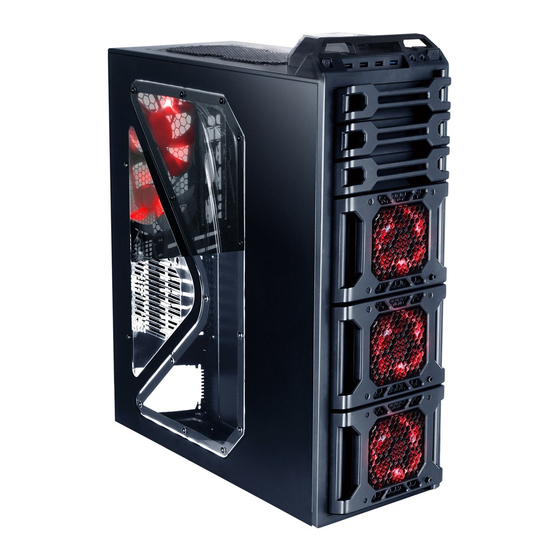
PECIFICATIONS Full Tower Matte black OLOR - 23.5” (H) x 8.5” (W) x 19.9” (D) IMENSIONS - 596 mm (H) x 213 mm (W) x 505 mm (D) 26.3 lbs / 11.3 kg EIGHT 2 x top 140 mm TwoCool™ fans OOLING 2 x rear 120 mm TwoCool™... -
Page 7: Before You Begin
Antec cases feature rounded edges that minimize the occurrence of hand injuries. Nonetheless, exercise caution and control when handling case interiors. We strongly recommend taking the appropriate time and care when working inside the case. Avoid hurried or careless motions. Please use reasonable precaution. -
Page 8: Locating And Positioning Your Computer
OCATING OSITIONING OMPUTER Your DF-85 has backwards- and top-facing exhaust fans, as well as front-mounted intake fans and one side- mounted front air intake. For optimum performance, we recommend leaving the front air intakes unobstructed. When open, the DF-85’s Fleet-Release™ doors take up an additional 15.5 cm of space in the front. Since loading and unloading the DF-85’s internal Fleet-Swap™... -
Page 9: Section 2 Hardware Installation
ECTION ARDWARE NSTALLATION... -
Page 10: Setting Up
ETTING Put the case upright on a flat, stable surface so that the rear panel (power supply and expansion slots) is facing you. To remove the left and right side panels, remove these thumbscrews: Note: Place the panel thumbscrews aside carefully and remember where they are. - Page 11 Now rest your case with the left side up. Here’s what we’ll be working with first: A – Power supply mounts B – 5.25” drive bay area C – 3.5” drive bay area with Fleet-Swap SATA bays D – Front panel wiring E –...
-
Page 12: Motherboard Installation
OTHERBOARD NSTALLATION Before proceeding: Check the manual for your CPU cooler to find out if there are steps you must do before installing the motherboard Make sure you have the correct I/O panel for your motherboard. If the panel provided with the case isn’t suitable, please contact your motherboard manufacturer for the correct I/O panel. - Page 13 Lift your motherboard out to install the standoffs. Install standoffs as needed and put the motherboard back in. Screw in your motherboard to the standoffs with the provided Phillips-head screws. Caution: Make sure to remove any unused motherboard standoffs. They may come into contact with the back of the motherboard and may electrify your case exterior if left connected.
-
Page 14: Standard Atx Power Supply Installation
UPPLY NSTALLATION The DF-85 can accommodate either a standard-size power supply or an Antec CPX form factor CP-series high performance power supply. Open the case. With the case upright, place the power supply on the four silicone pads on the bottom of the case. -
Page 15: Installing Acpx Form Factor Power Supply
OWER UPPLY The DF-85 can accommodate an Antec CPX form factor CP-series high performance power supply. An adapter plate for standard power supplies is pre-installed with standard Phillips-head screws and must be removed for a CPX form factor power supply to be installed. -
Page 16: Cable Management
With the case upright, place the power supply on the four silicone pads on the bottom of the case. Push the power supply to the back of the case and align the mounting holes, and attach the power supply to the case with the screws provided. ABLE ANAGEMENT There is a cable management compartment between the motherboard and right side panel, as well as cable ties... -
Page 17: Internal 3.5" Device Installation
For cables which will be routed back to front drives or other internal accessories, feed the cables back through the insertion point nearest the destination of the cable. Connect the cable and then pull the slack back to the right side of the case. For cables which will be routed directly to front drives or other internal accessories, cable tiedowns are located along the drive cage. - Page 18 The DF-85 includes three Fleet-Release™ access doors. With the front bezel facing you, they are located by default on the bottom nine drive bay slots (each door covers three drive bays). Open the Fleet-Release access door. Gently press the left side to release it, and then swing it open. Note: Do not attempt to open up the Fleet-Release™...
-
Page 19: Using Fleet-Swap
Installing a 3.5” internal device Fasten the device in place with the provided screws on both side of the drive cage. Make sure to install screws on the left side… …as well as the right side. Mount any other 3.5” HDD devices accordingly. Connect the appropriate power and data cables to the device(s), using cable routing as desired. - Page 20 Fleet-Swap™ default locations A – Fleet-Swap™ SATA and power connectors B – Fleet-Swap™ bay screws You may wish to move the Fleet-Swap bays. There are two screws securing each Fleet-Swap bay to the drive cage. To move or remove the Fleet-Swap bay, remove these screws, slide the Fleet-Swap bay towards the side opposite the screws, and carefully remove it.
- Page 21 Moving or removing a Fleet-Swap™ bay Now move the Fleet-Swap bay to the desired location, secure it in place and screw it in. Fleet-Swap bays can be relocated to anywhere in the 3.5” drive cage. Before you can use the hot-swap feature of the Fleet-Swap™ bays, you must install all related drivers for your motherboard and enable the “AHCI”...
- Page 22 Loading a Fleet-Swap drive. Mount any other 3.5” HDD devices accordingly. Close the Fleet-ReleaseTM Access Door. C. U ™ NLOADING THE LEET BAYS Ensure that your HDD is not in use. Open the Fleet-Release Access Door by pressing the left side to release it, and then swing it open. Open the Fleet-Release Access Door to access the drive you want to unload.
- Page 23 Removing a Fleet-Swap drive Close the Fleet-Release Access Door.
-
Page 24: Using The Top 2.5" Hot-Swap Bay
2.5” H SING The DF-85’s top 2.5” hard drive bay is hot-swap capable. To use the hot-swap feature, ensure that your motherboard is configured for hot-swap. Make sure to install all related drivers that come with your motherboard and turn on the AHCI function in the BIOS to activate the hot swap feature. Using the top 2.5”... - Page 25 Slide your 5.25” device into the bay from the front of the case. 5.25” device installation Secure the drive into position in the drive bay using the provided screws on each side of the drive. Mount any other 5.25” devices accordingly. Connect the appropriate power and data cables to your device(s).
-
Page 26: Section 3 Front I/Oports
ECTION RONT ORTS... -
Page 27: Usb 2.0
USB 2.0 Connect the front I/O panel USB cable to the USB header pin on your motherboard. Check your motherboard user’s manual to ensure that it matches the table below: Signal Names Signal Names USB Power 1 USB Power 2 Negative Signal 1 Negative Signal 2 Positive Signal 1... -
Page 28: Power Switch / Reset Switch / Hard Disk Drive Led Connectors
LED C OWER WITCH ESET WITCH RIVE ONNECTORS Connected to your front panel are LED and switch leads for power, reset, and HDD LED activity. Attach these to the corresponding connectors on your motherboard. Consult your motherboard manual for specific pin header locations. -
Page 29: Section 4 Cooling System
ECTION OOLING YSTEM... -
Page 30: Included Fans
NCLUDED FANS Standard fans on the DF-85: A –2 x 120 mm rear TwoCool™ fans B – 2 x 140 mm top TwoCool™ fans C – 3 x Fleet-Release access door modules w/front variable-speed 120 mm red LED fans Rear fan control panel... - Page 31 ™ F The DF-85 comes with two 140mm TwoCool™ fans. This fan has a two-speed switch that lets you choose the speed best suited to your need. These two switches are located at the rear of the case. The default fan speed setting is Low.
-
Page 32: Rear Exhaust 120 Mm Twocool™ Fans
There is one optional 120mm fan mount on the left side panel. A fan can be placed here to enhance graphics card cooling. We recommend using Antec 120mm TriCool™ fans and setting the speed to Low. This fan brings cool air into the case. -
Page 33: Washable Air Filters
ASHABLE ILTERS There is a filter located behind the faceplate of each Fleet-Release Access Doors. There are total of three front air filters that come with the case. Removing the washable air filter. Note the filter tabs. To clean the filter: Open the Fleet-Release Access Doors. -
Page 34: Water Cooling
ATER OOLING This case comes with a 5.25” metal plate pre-installed in the 3 5.25” drive bay. This is designed to mount your water-cooling hardware (such as a water pump or a reservoir). In addition, water cooling grommets are located at the back of the case, allowing you to run water cooling hoses through. Water cooling grommets... - Page 35 US & Canada 1-800-22ANTEC customersupport@antec.com Europe +31 (0) 10 462-2060 europe.techsupport@antec.com www.antec.com © Copyright 2010 Antec, Inc. All rights reserved. All trademarks are the property of their respective owners. Reproduction in whole or in part without written permission is prohibited.
Need help?
Do you have a question about the Dark Fleet DF-85 and is the answer not in the manual?
Questions and answers