dji O4 AIR UNIT Series, O4 Air Unit / Unit Pro Manual
- User manual (23 pages)
Advertisement
Using this Manual
Legend
 Important
 Hints and Tips
Video Tutorials
Go to the address below or scan the QR code to watch the tutorial videos, which demonstrate how to use the product safely:

https://www.dji.com/o4-air-unit/video
Download DJI Assistant 2
Download DJI ASSISTANT 2 (Consumer Drones Series) at:
https://www.dji.com/downloads/softwares/dji-assistant-2-consumer-drones-series
Product Overview
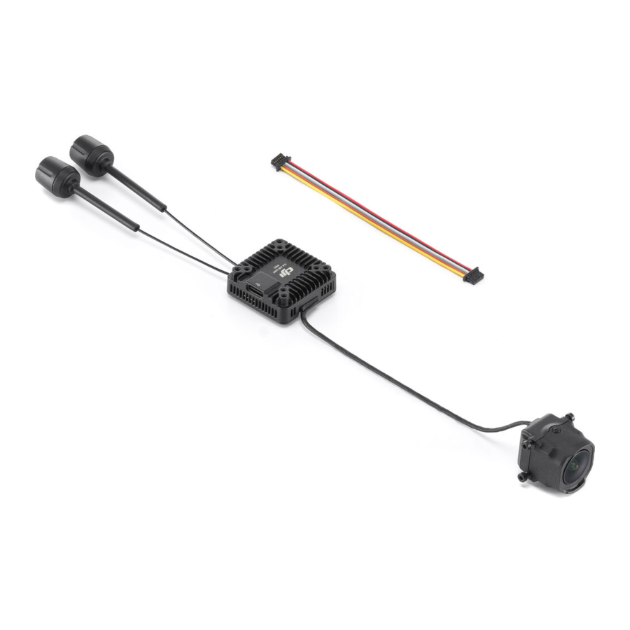
Overview

- Camera Module
- Coaxial Cable
- 3-in-1 Cable
- USB-C Port
- Antennas
- Link Button
- Linking Status Indicator
- microSD Card Slot
![information]() Some diagrams in the document use only DJI O4 Air Unit Pro for illustration. Refer to the relevant sections based on the product you purchased.
Some diagrams in the document use only DJI O4 Air Unit Pro for illustration. Refer to the relevant sections based on the product you purchased.
Dimensions
- Product dimensions are shown (unit: mm). Maintain enough space for installation.
- Mounting hole specifications are shown (unit: mm). Choose screw length based on the aircraft frame thickness. The screws included with the camera can only be used for frames thicker than 2 mm.


Specifications
Visit the following website for specifications.
https://www.dji.com/o4-air-unit/specs
Installation
Important Notice
- DO NOT apply pressure to or bend the base of the coaxial cable. Improper operation will result in image interruption or quality degradation.
- The standby time from cold start for the DJI O4 Air Unit Pro and DJI O4 Air Unit is 20 minutes and 2.5 minutes respectively. *
* Measured under idle conditions in an open environment at 25°C (77°F), for reference only. Restricted by its cooling condition, extra ventilation and heat dissipation measures are necessary when installing the air unit. Installation way may affect the heat dissipation.
The video transmission module can apply different temperature control strategies according to the standby and flight states.
- Ground temperature control strategy: In the standby state, the protection system will be activated to automatically shut down the air unit after overheating. When used with the DJI FPV Remote Controller 2, the goggles will prompt an overheating alert and restrict takeoff if the RF module exceeds a certain temperature.
- In-Flight temperature control strategy: There will be a prompt alert after overheating and the video recording will end. If the aircraft continues to overheat, the video transmission quality will be reduced to improve heat dissipation.
Installation Guidelines
![]()
DO NOT expose the video transmission module and camera module during usage to avoid accidental contact and potential burns. Make sure to install the air unit inside the aircraft body and in a well-ventilated location (such as near the air intake or exhaust) to prevent overheating, which may cause video transmission interruption.- Recommended installation practices that are effective for ventilation and heat dissipation:
- Mount the air unit in a position close to the propellers (distance between the air unit module and the propellers within 1 cm) so that the downwash can be effectively utilized.
- Use a heat conductive material to connect the frame and the air unit module. This will dissipate heat to the carbon plate and the other non-conductive metal components of the frame, thereby extending the operating time.
- DO NOT install the air unit in an enclosed area.
- Recommended installation practices for the antennas:
- The antenna should maintain a distance of at least 5 cm from the video transmission module, camera module, metal structural parts, and carbon fiber structural parts. It is recommended to position the two antennas of the DJI O4 Air Unit Pro at a 90-degree angle for optimal performance.
- Make sure that the antenna extends out of the aircraft frame and is not obstructed by any structural parts. After installation, confirm that the antenna is clearly visible from both the front and rear of the aircraft.

The metal shell of the air unit will become hot after being powered on so it should not be installed in a position that is easily accessible or held by hand.
Installation and Connection
- Operate with caution. Be careful not to scratch any components on the surface of the circuit board to avoid damaging the product.
- DO NOT overtighten the screws to avoid stripping.
- Make sure to follow the wiring sequence instructions when connecting the 3-in-1 cable to your flight controller properly. If using soldering, prepare a soldering iron and solder by yourself. Ensure the solder joints are firm and there are no short circuits or open circuits.


| VCC | Red | Power DJI O4 Air Unit: 3.7-13.2 V DJI O4 Air Unit Pro: 7.4-26.4 V |
| GND | Black | Power GND |
| Receiver | White | UART_RX (Connects to flight controller OSD TX, 0-3.3 V) |
| Transmitter | Grey | UART_TX (Connects to flight controller OSD RX, 0-3.3 V) |
| GND | Brown | Signal GND |
| S.Bus | Yellow | DJI HDL (Connects to flight controller S.Bus, 0-3.3 V) |
- Install the video transmission module with screws.
- There are directional requirements for the camera installation, make sure to distinguish the upward direction according to the figure. Install the camera module with the screws. Properly route the coaxial cable to avoid conflicts with other cables.
- Secure the antennas. Make sure the antenna extends out of the aircraft frame and is not obstructed by any structural parts. It should be at least 5 cm away from the video transmission and camera modules, and as far as possible from metal and carbon fiber structural parts.


DJI O4 Air Unit
- It is recommended to install M2 flight controller damping balls on the screw holes of the video transmission module.
- If using a 1S battery as the power supply, try to minimize the voltage drop. For example, use short cables to ensure the voltage of the video transmission module port is greater than 3.7 V.
- If using BEC power supply, ensure that the BEC output power is at least 10 W (e.g., 5 V/2 A).
DJI O4 Air Unit Pro
- If using adhesive to install the video transmission module, it can only be applied on the side without heat dissipation fins.
- If using BEC power supply, ensure that the BEC output power is at least 13.5 W (e.g., 9 V/1.5 A).
Preparation Before Use
Activation
Make sure to activate the device before using for the first time. Otherwise, some functions will be unavailable.
- If the air unit is not activated, its transmission power will be limited (≤20 mW), and the menu screen of the connected goggles cannot be operated.
- If the goggles are not activated, only linking is available and the menu screen cannot be operated. Additionally, the device will also be set in the public channel and cannot be set to other channels after linking. Note that the public channel is easily prone to interference from other transmission devices.
- Visit https://www.dji.com/o4-air-unit/downloads to download the DJI Assistant 2 (Consumer Drones Series).
- Power on the video transmission module, and connect it to a computer via the USB-C port.
- Launch DJI Assistant 2 and log in with a DJI account.
- Select and activate the device according to the onscreen prompts.
Firmware Update
- Launch DJI Assistant 2, select the product, and click the firmware update button on the left side.
- Select the firmware version.
- Wait for the firmware to download. The firmware update will start automatically.
- Restart each device after the firmware updates are complete.
- It is recommended to detach the propellers to avoid danger caused by accidental motor startup.
- Visit https://www.dji.com/o4-air-unit to check supported DJI goggles and remote controllers.
Goggles Home Screen and Menu
Get familiar with the goggles interface and functions before using. Visit the goggles official website for detailed usage information.
Linking
Make sure that all devices have been updated to the latest firmware versions before linking.
The following example shows how to link the DJI Goggles 3 and DJI FPV Remote Controller 3.

Figure A: Linking Goggles and the Air Unit
- Power on the air unit, the goggles, and the remote controller. Enter the goggles menu, select Status, and click the upper right corner to select the product.
- Make sure the linking status indicator of the air unit is red. Press the link button once, the linking status indicator blinks red. Press the link button on the goggles. The goggles will start to beep continually.
- Once linking is successful, the linking status indicator of the air unit turns solid green. The goggles stop beeping and the live view will be displayed.
Figure B: Linking Goggles and Remote Controller
- Activate the linking status on both the goggles and the remote controller. The goggles starts to beep continually. The remote controller starts to beep continually and the battery level LEDs blinks in sequence.
- Once linking is successful, the goggles will stop beeping and display the live view, and the remote controller will stop beeping.
The linking order may vary when link the air unit with different models of goggles and remote controllers.
Usage
Video Recording
Make sure the air unit, the goggles, and the remote controller are connected.
Once a microSD card is inserted to the goggles and the Record With is set to Both, while the aircraft is recording video, the goggles will simultaneously record the flight live view displayed on the screen and store it on the microSD card of the goggles.
The air unit and goggles will stop recording when the motors stop. The recording will automatically stop when the following occurs.
Air Unit
- The microSD card is full or an error occurs during recording;
- The air unit enters low-power mode because its temperature is too high;
- When the aircraft is on the ground and awaiting takeoff, the automatic low-power mode is enabled by default and the air unit cannot start recording.
Goggles
- The microSD card is full or an error occurs during recording;
- The transmission signal is lost, or exits live view;
- The live view source is changed, such as switching between Player to Audience mode.
- The googles switch to Real View during recording.
Powering off the device or removing the microSD card during recording will result in a corrupted video file, which cannot be played. Insert the microSD card into the device again, and the device will attempt to recover the corrupted video file automatically after powering on. DO NOT disconnect the power during the recovery process.
Setting Transmission Power
This product supports selecting different transmission power levels. The transmission power can be set in the goggles menu as follows:
Open the goggles menu, select Transmission > Transmission Power, and then select Auto or Manual according to the actual situation.
After selecting a fixed transmission power level, you can use the Transmission Power Fine-Tuning feature in the transmission menu. This allows for adjustments of up to ±6 levels, with each level adjusting by 0.5 dB.
- DJI O4 Air Unit: The maximum available transmission power levels are 25mW, 50mW, 100mW, 200mW, 400mW, and 700mW.
- DJI O4 Air Unit Pro: The maximum available transmission power levels are 25mW, 50mW, 100mW, 200mW, 400mW, 700mW, and 1200mW.
- As regulations vary by country and region, the available transmission power levels are different.
- When the transmission power is set to exceed 700mW, the air unit will automatically adjust the transmission power between the set value and 700mW based on the flight environment to achieve the optimal transmission performance.
Setting Operating Channel
- Enter the goggles menu, go to Transmission > Channel Mode.
- Select between Auto and Manual mode based on actual needs.
Auto mode: The device will automatically select the channel with optimal signal strength between 5.170GHz and 5.250GHz or between 5.725GHz and 5.850GHz.
Manual mode: the channel can be manually selected from the following bandwidths.
| Bandwidth | Channel and the Corresponding Central Frequency |
| 40 MHz | Channel 1: 5794.5 MHz |
| 20 MHz | Channel 1: 5768.5 MHz Channel 2: 5789.5 MHz Channel 3: 5814.5 MHz |
| 10 MHz | Channel 1: 5768.5 MHz Channel 2: 5789.5 MHz Channel 3: 5814.5 MHz |
Power on and connect the air unit to a computer and run DJI Assistant 2 (Consumer Drones Series). The air unit will update to the radio mode of the current region automatically. When the goggles or remote controller are connected to the air unit, the region of their radio modes will also update automatically.
- Only manual mode is available when in racing mode.
- When used with certain models of goggles (such as DJI Goggles 3), a channel bandwidth of 60 MHz is also available, corresponding to a center frequency of 5794.5 MHz.
- Make sure you fully understand and abide by local laws and regulations before using this product.
- Some channels may not be available in some countries due to regulatory restrictions.
Racing Mode
Racing mode is supported when used with the following goggles. Go to the Transmission menu of the goggles to enable or disable this feature.
- DJI Goggles 3
- DJI Goggles N3
Once the racing mode is enabled, the related settings will be automatically adjusted as follows:
- The channel can only be set manually, with a maximum of 8 racing channels available.
- The bandwidth can be set to either 20 MHz or 40 MHz.
- The video resolution are automatically set to 1080p@100fps (4:3) and cannot be manually adjusted.
- The anti-interference feature is disabled, and the transmission bitrate is reduced for minimum transmission latency.
- Due to regulatory restrictions, the maximum number of supported racing channels varies by country and region.
- Use racing mode in an appropriate area, as the anti-interference capability is disabled in this mode.
- Allocate racing channels in advance and control transmission power to avoid interference when flying multiple devices simultaneously
Canvas Mode
Canvas Mode enables the flight controller to display OSD elements (such as battery voltage and flight distance) on the screen of the goggles. You can use the Betaflight Configurator software to configure which OSD elements to display and their positions on the screen.
Canvas Mode is compatible with Betaflight Configurator 4.3.0 and later. Configuration steps for Canvas Mode vary depending on the software version. Refer to the configuration guide for the version you use. Below are the basic configuration steps.
- Hardware connection: Connect the UART RX port of the air unit to one of the UART TX serial ports (UART4 is used as an example) of the flight control board.
- UART configuration: Open Betaflight Configurator and select Ports. Turn on the MSP switch for the corresponding UART TX serial port (UART4) and set baud rate to 115200. Click Save and Reboot.
If Betaflight Configurator 4.4.0 or later is used, set Peripherals to MSP+Displayport. In this case, you can skip the CLI configuration below. - CLI configuration: In Betaflight Configurator, select CLI and execute the following commands:
- Set osd_displayport_device to MSP:
set osd_displayport_device = MSP - Specify the MSP serial port number, which equals the UART TX serial port number minus 1. In this example, set the number to 3.
set displayport_msp_serial = 3 - Save and exit:
Save
- Set osd_displayport_device to MSP:
EIS Usage Notice
Issues
- Video image shakes when RockSteady is enabled.
- Mechanical vibration at certain frequencies results in abnormal EIS (electronic image stabilization) performance of the air unit.
Causes
- IMU resonance
- The default ESC (electronic speed control) PWM (pulse-width modulation) control frequency is 24 kHz, and the camera IMU frequency is around 24 to 30 kHz. Without effective vibration absorption, motor vibrations can transfer to the camera IMU, causing resonance due to frequency overlap. The resonance will affect the IMU data accuracy and EIS performance of the video stabilization application. * As a result, the processed video image shakes, but the liveview image is not affected.
- Usually, frames with TPU or vibration absorbing rubber are not prone to the IMU resonance issue.
- Rolling shutter effect
- If the rolling shutter effect appears in both the liveview and the video image, it is usually because the propeller vibration (frequency is approximately a few hundred Hz) is transmitted to the camera through the aircraft frame.
* Video stabilization application includes the built-in EIS function of the air unit and the video stabilization function provided by third-party software
Solutions
Follow the steps below.
- Troubleshoot the IMU resonance issue
- Preparation:
- Remove the propellers from the aircraft. Make sure that the camera is securely mounted and the aircraft is placed stationary on the ground.
- Then, enable RockSteady and start recording.
- Run a test:
- Start the motors and slowly push the throttle to the full position.
- Observe the liveview in the goggles.
- If the liveview is not shaking, stop the motors and end the recording. Otherwise, check the camera and make sure it is securely mounted.
- Check the recording:
- Export and play the recorded video.
- If the video image shakes, the issue is most likely caused by the resonance between the frame and the camera IMU. In this case, try the following solutions:
- Change the ESC PWM control frequency to 48 kHz or 96 kHz and test again.
- If the video image still shakes, apply a softer vibration absorbing structure * between the camera and the aircraft frame. Repeat the preceding test until the video image does not shake.
* Due to the significant weight difference between DJI O4 Air Unit and DJI O4 Air Unit Pro, DJI O4 Air Unit requires a softer vibration absorbing structure to achieve the same effect as DJI O4 Air Unit Pro.
- Preparation:
- Troubleshoot the rolling shutter effect issue
After troubleshooting the IMU resonance issue, check whether the video image has the rolling shutter effect.- Replace the propellers if there is any damage. Then, fly the aircraft and start recording with RockSteady enabled.
- Check the video image after the flight. If there is no rolling shutter effect, the troubleshooting process is complete. If the video image has a rolling shutter effect, try the following solutions:
- Adjust the vibration absorbing structure between the camera and the aircraft frame again.
- Adjust the tightness of the screws to fasten the camera to the aircraft frame.
If the issue persists after attempting all the above methods, contact technical support.
Maintenance
Parts Replacement
Click the link below to watch the tutorial video. https://www.dji.com/o4-air-unit/video
After-Sales Information
Visit https://www.dji.com/support to learn more about aftersales service policies, repair services, and support.
Important Notice
- The air unit may become hot during or after operation. DO NOT touch the air unit before it cools down.
- DO NOT use the air unit for an extended period in high-temperature environments with poor ventilation. Otherwise, the air unit may overheat and enter low-power mode, which will affect the performance.
- When powered on, the air unit automatically enters low-power mode to prevent overheating, which can degrade image transmission performance. Once the aircraft takes off or recording starts, the air unit exits low-power mode and resumes normal performance. Ensure that the aircraft takes off promptly or that the air unit is well-ventilated.
- Make sure that the external power supply for the air unit meets the specification. Failure to do so may result in malfunction or damage to the unit.
- DO NOT connect the power cable directly to the power GND cable or plug/ unplug the cables when the air unit is powered on. Otherwise, the unit may be damaged.
- DO NOT obstruct or twist the antenna of the air unit. Otherwise, transmission may be affected or blocked.
- Make sure to follow the instructions when installing the air unit. Incorrect installation may cause abnormal performance or even damage to the air unit.
- Keep the electronic devices as far away from each other as possible during installation to minimize electromagnetic interference.
- Make sure that all connections are secure and all parts are working properly.
- Make sure that there are no other transmitting devices in the surrounding area that may cause interference. DO NOT use the same frequency band as other devices. Otherwise, the transmission performance will be affected.
- Make sure you fully understand and abide by local laws and regulations before using this product.
- This product is not intended for children.
- Dispensing is applied to certain electronic components of DJI O4 Air Unit. DO NOT tamper with these areas. Otherwise, flight safety may be compromised.
Documents / Resources
References
![www.dji.com]() DJI O4 Air Unit Series - Tutorials - DJI
DJI O4 Air Unit Series - Tutorials - DJI![www.dji.com]() DJI Assistant 2 (Consumer Drones Series) - Download Center - DJI
DJI Assistant 2 (Consumer Drones Series) - Download Center - DJI![www.dji.com]() DJI O4 Air Unit Series - Specs - DJI
DJI O4 Air Unit Series - Specs - DJI![www.dji.com]() DJI O4 Air Unit Series - Downloads - DJI
DJI O4 Air Unit Series - Downloads - DJI![www.dji.com]() DJI O4 Air Unit Series - DJI
DJI O4 Air Unit Series - DJI![www.dji.com]() Support - DJI
Support - DJI
Download manual
Here you can download full pdf version of manual, it may contain additional safety instructions, warranty information, FCC rules, etc.
Download dji O4 AIR UNIT Series, O4 Air Unit / Unit Pro Manual
Advertisement


Need help?
Do you have a question about the O4 AIR UNIT Series and is the answer not in the manual?
Questions and answers