Advertisement
Specifications
| X99PR9 | |||
| Processor | Intel Xeon E5 LGA2011‐3 series processor | ||
| Southbridge | Q85 Chipset | ||
| RAM | Technology | 4‐channel DDR4 2133/2400/2666/3000/3200MHz | |
| Maximum Capacity | 128GB (32GB*4) | ||
| Memory Slot | 4 * DDR4 | ||
| Rear I/O | USB | 6 * USB 2.0;2 * USB3.0 | |
| Ethernet | 1 * Gigabit LAN Card | ||
| Video | 0 | ||
| PS/2 | 1 | ||
| AUDIO | 1 (Mic‐in, Line‐out、Line‐in) | ||
| Internal connector | CFAN | 2 * 4PIN CPU_FAN | |
| ATXPWR Interface | 1 * 8PIN Power Socket; 1 * 24PIN Power Socket | ||
| USB2.0 | 1 | ||
| USB3.0 | 1 | ||
| M.2 | 1(NVME M.2/SATAM.2) | ||
| SATA Interface | 3 * SATA3.0 | ||
| JAUDIO | 1 * 2x5Pin | ||
| PCIe | 1 * PCIe x16; 1 * PCIe x1 | ||
| JCMOS Port | 1 | ||
| SPK Port | 1 | ||
| Environment | Temperature Range | Working Environment | Storage Environment |
| Temperature: 0~50°C Humidity: 5%~95% | Temperature: ‐20~70°C Humidity: 5%~95% | ||
| Physical Size | Size | 215mm*185mm | |
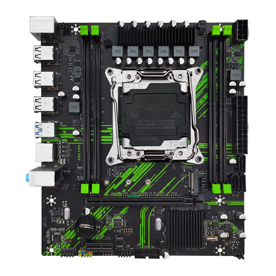
Overview of Components

Package List:
X99 PR9 Motherboard * 1
SATA Cable * 1
I/O Blocking * 1
LGA2011‐3 Cooler Bracket Mounting Kit * 1
Install CPU & Fan
Please install the CPU into the CPU socket (LGA 2011‐3) as shown below.


- Make sure that the motherboard supports the CPU.
- Always unplug the power cord from the power outlet before installing or removing theCPU to prevent hardware damage.
- Please retain the CPU protective cap after installing the processor.
- Do not turn on the computer if the CPU cooler is not installed, otherwise overheating and damage to the CPU may occur.
- Confirm that the CPU heatsink has formed a tight seal with the CPU before booting your system.
- Apply an even layer of thermal paste (or thermal tape) between the CPU and the heatsinkto enhance heat dissipation.
- Whenever the CPU is not installed, always protect the CPU socket pins by covering thesocket with a plastic cap.
- Locate the pin one of the CPU socket and the CPU. Once the CPU is positioned into itssocket, place one finger down on the middle of the CPU, lowering the locking lever and latching it into the fully locked position.
- Do not force the CPU into the CPU socket before the CPU socket locking lever is lifted up, or damage to the CPU and CPU socket may occur.
- Connect the CPU heatsink's 4pin fan power connector to the 4pin CPU fan header on the motherboard.
- Please be sure to plug in the 8‐PIN power supply to power the CPU.
Install Memory
The motherboard provides 4 DDR4 DIMM slots, each with a maximum capacity of 32GB.

- Wrench the latches on both sides of the memory slot outwards.
- Insert the memory into the slot by aligning it with the notch in the slot.
- Flip the latches on both sides of the slot to lock the memory.
- Make sure that the motherboard supports the memory. It is recommended that memoryof the same capacity, brand, speed, and chips be used.
- Always turn off the computer and unplug the power cord from the power outlet beforeinstalling the memory to prevent hardware damage.
- Memory modules have a foolproof design. A memory module can be installed in only onedirection. If you are unable to insert the memory, switch the direction.
- The stability and compatibility of the installed memory module depend on the installedCPU and devices when overclocking.
- This motherboard provides 4 memory sockets and supports quad‐channel Technology. Install 4 memory modules to enable quad‐channel mode, and install 2 to enable dual‐channel mode.
- When installing memory, please install the slot close to the CPU first, as following:
| DIMMD1 | DIMMD2 | DIMMB1 | DIMMB2 | |
| 1 Module | Y | ‐‐ | ‐‐ | ‐‐ |
| 2 Modules | Y | ‐‐ | Y | ‐‐ |
| 4 Modules | Y | Y | Y | Y |
("Y"=Install memory, "‐ ‐"=No Memory)
Install Expansion Card
The motherboard provides 1 PCI Express 3.0 x16 expansion slot and 1 PCI Express 3.0 x1 expansion slot.
Place the expansion card in an available PCI Express slot and press the expansion card until it is fully inserted into the slot.

- When adding or removing expansion cards, always turn off the power supply and unplugthe power supply power cable from the power outlet to prevent hardware damage.
- If the expansion card is not installed correctly, it may cause a short circuit throughout themetal pins, which could burn out the expansion card or the motherboard.
Back Panel Connectors

USB 2.0 Port
The USB port supports the USB 2.0 specification. Use this port for USB devices.
USB 3.0 Port
The USB 3.0 supports the USB 3.0 specification and is compatible to the USB 2.0 specification. Use this port for USB devices.
RJ45 LAN Port
The Gigabit Ethernet LAN port provides Internet connection at up to 1000Mbps/s data rate. The following describes the states of the LAN port LEDs.

Audio Port
Line‐in Port
The line in jack. Use this audio jack for line in devices such as an optical drive, walkman, etc.
Line‐out Port
The line out jack.
Mic‐in Port
The Mic in jack.
PS/2 Port
The PS/2 port of the mouse is green, and the PS/2 port of the keyboard is blue.
Internal Connectors
F_PANEL1 Connector

SPK1 Connector

F_AUDIO1 Connector
This connector allows you to connect audio jacks on the front panel.

- An incorrect connection between the module connector and the motherboard header will make the device unable to work or even damage it.
SATA1~3: SATA 3.0 Connectors
These SATA 3.0 connectors are SATA 6Gb/s interface ports. Each SATA connector supports a single SATA device.

M.2 Slot
This motherboard has 1 M.2 slot, support NVME M.2/NGFF M.2 SSD.

Insert your M.2 SSD into the M.2 slot at a 30‐degree angle. Secure the M.2 SSD in place with the screw.

JCMOS1: CMOS Discharge

- Always turn off the computer and unplug the power cord from the power outlet before discharging.
ATXPWR1, PW1: Power Connectors
With the use of the power connector, the power supply can provide enough stable power to all the components on the motherboard. Before connecting the power connector, make sure the power supply is turned off and all devices are properly installed.
24PIN for motherboard power supply.
8PIN for CPU power supply.
- It is recommended that a power supply that can withstand high power consumption be used (at least 500W). If a power supply is used that does not provide the required power, the result can lead to an unstable or unbootable system.

CPU_FAN1~2: Fan Connectors
CPU_FAN is a interface for CPU radiator. The 4pin fan has PWM intelligent speed regulation function, which can intelligently control the fan speed based on load and temperature changes.

J_USBA1: USB 3.0 Connector
The header conforms to USB 3.0 and USB 2.0 specification. This connector allows you to connect USB 3.0 ports on the front panel.

F_USB2: USB 2.0 Connector
The headers conform to USB 2.0 specification. This connector allows you to connect USB 2.0 port on the front panel.

BIOS Setup
BIOS (Basic Input and Output System) records hardware parameters of the system in the CMOS on the motherboard. BIOS identifies, configures, tests and connects computer hardware to the OS immediately after a computer is turned on.
Its major functions include conducting the Power‐On Self‐Test (POST) during system startup, saving system parameters and loading the operating system, etc. BIOS includes a BIOS Setup program that allows the user to modify basic system configuration settings or to activate certain system features.
When the power is turned off, the battery on the motherboard supplies the necessary power to the CMOS to keep the configuration values in the CMOS.
- Because BIOS flashing is potentially risky if you do not encounter problems using the current version of BIOS, it is recommended that you not flash the BIOS. To flash the BIOS, do it with caution. Inadequate BIOS flashing may result in system malfunction.
BIOS Setup
The default settings offer the optimal performance for system stability in normal conditions. It is recommended that you not alter the default settings (unless you need to) to prevent system instability or other unexpected results. Inadequately altering the settings may result in the system's failure to boot.
- BIOS items are regularly updated for better system performance. The items may be slightly different from the latest BIOS; therefore, the description is for reference only.
Enter BIOS Setup
When the computer starts up, BIOS enters the self‐test process. When the self‐test is completed, the following message is displayed: Press DEL key to enter Setup Menu. At this time, Press <Delete> key to enter the BIOS setup.
If this message disappears before you press <DEL> key, you can turn it off and then turn on your computer or press <Reset> on the case to restart your computer. You can also press <Ctrl>+<Alt>+<Delete> at the same time to restart your computer.
- Functions may vary depending on the product you have.
Reset BIOS
When you need to restore the default BIOS settings to resolve certain issues, there are several ways to reset the BIOS:
- Go to BIOS and press F6 to load optimized defaults.
- Short the Clear CMOS jumper on the motherboard.
- Be sure the computer is off before clearing CMOS data. Please refer to the Clear CMOS jumper section for resetting BIOS.
FAQs
No Boot
Press the computer boot button, the computer does not respond (fan does not rotate, indicator light does not light).
- Clear CMOS.
- Check whether the CPU model is compatible with the motherboard.
- Check whether the motherboard power supply, CPU power supply is plugged in, chassispower switch is turned on.
- Check whether the chassis power‐on cable is plugged in properly.
- Check whether the power supply is good.
- Unplug the graphics card, hard disk, USB and other devices, and then try to boot (it is bestto use metal objects to directly short the switch pins, so that you can rule out the chassis switch problem).
- Replace the CPU.
Start‐up ‐ Shutdown
Press the start button and the fan turns for a while, then it turns off.
- Clear CMOS.
- Check whether the CPU model is compatible with the motherboard.
- Replace the CPU and troubleshoot if the CPU is bad.
- Replace the RAM and check if the RAM is bad.
- Unplug the graphics card, hard disk, USB device, and then reboot.
Repeated reboots
The computer will restart repeatedly.
- Clear CMOS.
- Check whether the CPU model is compatible with the motherboard.
- Replace the CPU and troubleshoot if the CPU is bad.
- Replace the RAM and check if the RAM is bad.
- Unplug the graphics card, hard disk, USB and other devices, and then reboot.
No Display
The fan is rotating, press the keyboard case‐switching key (CapsLK), the keyboard indicator does not respond.
- Clear CMOS.
- Check the motherboard power supply, CPU power supply is plugged.
- Check the location of the memory stick installation, determine whether the memorylocation is inserted correctly (some models of the motherboard memory slot can not be randomly inserted, if you are not sure, please contact us through the online communication tool).
- Check whether the CPU and memory model is compatible with the motherboard.
- Replace the CPU, check whether the CPU is bad.
- Replace the memory, check whether the memory is bad.
The fan is rotating, press the keyboard case‐switching key (CapsLK), the keyboard light responds.
- Check if the monitor is on.
- Check whether the monitor display cable is plugged in (DP,HDMI,DVI,VGA).
- If you are using a set of graphics (no external graphics card installed), check whether theCPU with integrated graphics (for example, the suffix with F CPU and Intel Xeon series CPU are not integrated graphics, you need to install an external graphics card to display).
- Check whether the monitor cable is inserted in the right place, not installed externalgraphics card, then inserted in the motherboard display interface; installed external graphics card, then have to be inserted in the graphics card display interface.
- Replace the monitor cable, check whether the monitor cable is bad.
- Replace the graphics card to check whether the monitor is bad.
Blue Screen, Crash
- Check whether the heat dissipation is done properly, whether the CPU cooler fan isrotating, whether the base of the cooler and the CPU are tightly fitted, and whether the thermal paste is applied.
- Replace the CPU.
- Replace the memory.
- Replace the hard disk.
- Replace the system.
- Replace the power supply.
Documents / ResourcesDownload manual
Here you can download full pdf version of manual, it may contain additional safety instructions, warranty information, FCC rules, etc.
Advertisement


Need help?
Do you have a question about the X99 PR9 and is the answer not in the manual?
Questions and answers