
Related Manuals for Servomex SERVOTOUGH OxyExact 2200 Series


Summary of Contents for Servomex SERVOTOUGH OxyExact 2200 Series
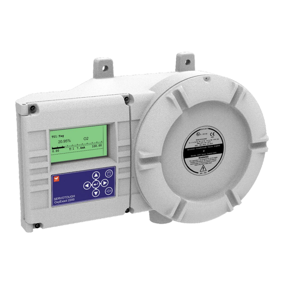
- Page 1 SERVOTOUGH OxyExact 2200 Series SERVICE MANUAL Part Number: 02200002A Revision: Language: UK English...
- Page 2 This page intentionally blank...
-
Page 3: Table Of Contents
Table of Contents INTRODUCTION..........1 1.1 Warnings, Cautions and Notes . - Page 4 Table of Contents 6.4 Output signal diagnostics ........30 6.4.1 mA output and status/alarm relay output checking .
- Page 5 SERVICE CHECK LIST ......... 59 SPARE PARTS .
- Page 6 This page deliberately left blank Service 2200 Series...
- Page 7 List of Figures List of Tables Figure 1 Analyser system configurations ......5 Figure 2 Measuring schematic .
- Page 8 This page deliberately left blank Service 2200 Series...
-
Page 9: Introduction
The electrical power used in this equipment is at a voltage high enough to endanger life. Servicing should only be performed by trained personnel. Service training is available from Servomex. Before carrying out servicing or repair the equipment should be disconnected from the electrical power supply. -
Page 10: Scope Of This Manual
The area must be made safe and shown not to contain explosive or flammable gases before covers are opened or work done on the analyser system. Any spare parts used must be as specified by Servomex. Replacement with non- approved parts will invalidate any safety certification. -
Page 11: Service Philosophy
Service philosophy WARNING All servicing should be referred to qualified personnel. Repairs to printed circuit boards are affected by module replacement. Component replacement is not recommended. The only exceptions to this are the mains fuses in the control unit and transmitter. Overview of this manual This manual is intended for operatives who are familiar with fault finding and servicing of instrumentation systems. -
Page 12: Shutdown Procedure
Shutdown procedure The sample conditioning system and analyser should be flushed with clean, dry gas before disconnecting electrical power. This will reduce the possibility of condensation and subsequent corrosion of the measuring cell. Any sources of possibly toxic or suffocating sample gases must be isolated. Before servicing the analyser system all sources of electrical power, including those to relay contacts or other inputs/outputs, must be disconnected. -
Page 13: System Overview
SYSTEM OVERVIEW The 2200 analyser system The Servomex 2200 system consists of a model 2210 or model 2213 Control Unit and one or more model 2222 and/or 2223 transmitter units. The units can be located on up to 1km of cable (total cable length). -
Page 14: The Control Unit
Options enable the 2200 analyser system to be configured with a range of analog outputs representing primarily oxygen concentration for each sample point, from both the individual transmitter units and the control unit. These outputs are freely programmable to any span and offset. Alarms include sample gas concentration and comprehensive diagnostics and status outputs. -
Page 15: The Transmitter Unit
0 and pure oxygen is 100, nitrogen is -0.39 and carbon dioxide is -0.69. This property is used in the Servomex measuring cell which is purely physical in measurement. As there are no chemicals, regular servicing or replacement are not required in normal use. -
Page 16: Figure 2 Measuring Schematic
Figure 2 Measuring schematic The measuring cell is sited in a focussed, non-linear, magnetic field. Any oxygen present will be attracted into the strongest part of the magnetic field. This displaces the nitrogen spheres and causes the suspension to rotate through a small angle. The photocells (initially equally illuminated) will detect the movement and generate a signal difference as the photocells are now illuminated differently. -
Page 17: Factors Affecting The Measurement
FACTORS AFFECTING THE MEASUREMENT NOTE The paramagnetic measuring principle used in the transmitter is normally a very stable technique. It is also a highly sensitive measurement and may reveal errors in the complete measuring system which are not faults in the gas analyser. This section provides some information on identifying and isolating the possible causes of errors and it is recommended that this section is read before performing any maintenance on the analyser system. -
Page 18: Pressure Compensation
Pressure compensation or regular ‘span’ calibration will remove this effect. If the measuring cell is not vented directly to atmosphere but to a vent header, the pressure in the measuring cell may vary due to external factors, i.e. changes in vent header pressure will change the pressure in the measuring cell. -
Page 19: The Use Of Sample Pumps
3.1.6 The use of sample pumps The measuring cell has an inherently fast response time. A pump may produce pressure pulses which may be detected as a change in oxygen value. In extreme cases this may cause instability. Any pumps should be installed correctly and be of adequate size, with pressure and flow control. -
Page 20: Spikes
Analog output is characterised by a noisy signal, but the average value is constant. Frequency and amplitude is variable. Such a signal may be the result of sample flow and/or pressure fluctuations. Recommendation – Turn the sample gas off. If the noise is no longer present investigate the sample system. -
Page 21: Ambient Effects
3.2.3 Ambient effects Figure 5 Analog output ambient effects This variation occurs over a significant time interval of possibly several days. The average value remains constant. This is generally not an analyser fault, but may be due to cyclic changes in sample gas (i.e. the process), atmospheric pressure or ambient temperature. -
Page 22: The Implications Of Calibration Gas Tolerances On Performance
The implications of calibration gas tolerances on performance The Servomex Paramagnetic Torque Balance measuring technique is inherently linear. As with any straight line graph, the best ‘fit’ results are obtained when the end points are far apart – since the effects of errors in the actual end points (in this case due to gas tolerances) is reduced. -
Page 23: The Sample Conditioning System
THE SAMPLE CONDITIONING SYSTEM Many analyser system problems can be traced to an inadequate sample conditioning system. General guidance The sample gas for the analyser must be: Free of dust and particulate matter. Free of condensate (both water and organics). At the correct flow rate. -
Page 24: Figure 8 Typical Sample System Components
It is advised that an inspection of the sample conditioning system should be done if the analyser system appears not to be performing to requirements. It is not possible to give detailed guidance as sample conditioning systems vary in design, however, the following are an indication of the points to be checked. - Page 25 Table 1 Sample system components (See Figure 8) Item Description Possible fault Action Pump with Pump failure, resulting in no Check operation of pump bypass or low flow Adjust bypass loop flow control Note presence of bypass loop for most efficient operation (may not be to prevent the pump required)
-
Page 26: Condensates
Condensates Condensed liquids must not be allowed to enter the measuring cell. Condensation in the cell will cause false readings and may permanently damage the cell. Often condensate can be seen in the sight glasses of flowmeters. If present the cell must be examined. -
Page 27: Setting Calibration And Sample Gas Flow Rates
Setting calibration and sample gas flow rates CAUTION All gas cylinders and gas sources must be fitted with pressure and flow controllers to ensure that the maximum flow and pressure requirements of the measuring cell are not exceeded. Damage to the cell can result if the gas pressure and flow rates are exceeded. Apply the low calibration gas and set the pressure and flow controls so that the flow through the measuring cell is <250ml/min (or, in certain versions of the 2223 type transmitter only, <1.0l/min for the high flow rate option). - Page 28 This page deliberately left blank Service 2200 Series...
-
Page 29: Description Of The Electronics
DESCRIPTION OF THE ELECTRONICS As previously stated, it is not possible to repair any of the circuit boards inside either the transmitter or associated control unit. The following block diagrams are only intended to facilitate fault finding down to board replacement level. Figure 9 provides details of the control unit. -
Page 30: Figure 9 Control Unit Block Diagram (Previous Processor)
Figure 9 Control unit block diagram (Previous Processor) Service 2200 Series... - Page 31 Figure 9a Control unit block diagram (Current Processor) Service 2200 Series...
-
Page 32: Figure 10 Transmitter Unit Block Diagram
Figure 10 Transmitter unit block diagram Service 2200 Series... -
Page 33: Figure 11 Signal Processing Block Diagram
RS485 A BACKLIGHT SUPPLY RS485B SUPPLY LOGIC P005 +5V6(ISO B) 0V(ISO B) HANDHELD BACKLIGHT SUPPLY +SUPPLY RS232 TX RS232 RX SOLID STATE RELAY DRIVE PROGRAM P004 +7V5 +5V1(A) +5V1(B) +5V6 +5V1(A) +7V5 +3V3 +5V1(B) +2V5REF HANDHELD LOGIC SUPPLY -2V5REF -5VUNREG 0V(ISO A) +22V(ISO A) P001... - Page 34 This page deliberately left blank Service 2200 Series...
-
Page 35: Initial Troubleshooting
INITIAL TROUBLESHOOTING If operational, the current status and status history screens for both the transmitter and control unit should be reviewed. This may lead the user directly to the source of the problem. Initial power-up Electrical power is supplied separately to the transmitter unit and control unit. Ensure that both units are connected and powered. -
Page 36: Calibration History
6.2.1 Calibration history The calibration history records all successful oxygen measurement checks and calibrations. This includes those that occur during autocalibration. The history may be reviewed to determine analyser stability over a long period of time. Internal diagnostic checks Information regarding the ‘health’ of the oxygen measurement may be gained by viewing the internal diagnostics, however, before viewing this information, an understanding of the measurement chain is recommended. -
Page 37: Transmitter Unit Diagnostics
6.3.1 Transmitter unit diagnostics Transmitter unit diagnostics is accessed under the relevant transmitter, service menu. In the following form, the value for the voltages are dependent on the oxygen concentration. A difference of 20% oxygen should produce a change of nominally 0.2V. -
Page 38: Output Signal Diagnostics
Fault and Maintenance messages will indicate if any of the above parameters are outside of normal limits, and may imply degradation of components within the measurement optics (as shown in Figure 2). This will result in a decrease in performance of the measuring system, which may be shown as: Excessive noise or drift: Oxygen value is either upscale or downscale (and fails to calibrate). -
Page 39: Internal Diagnostic Messages
Internal diagnostic messages The control unit may display a number of diagnostics messages. Aside from routine information, the following table lists such messages and possible causes. 6.5.1 Messages associated with the transmitter Such messages will usually be preceded with “T01”, “T02”, etc where 1, 2 etc is the address of the transmitter at fault. - Page 40 This page deliberately left blank Service 2200 Series...
-
Page 41: Hardware Diagnostics
HARDWARE DIAGNOSTICS WARNING The control unit and transmitter include circuits which are intrinsically safe. The connection between the transmitter and control unit is intrinsically safe. This must be considered when servicing one end of the system. Diagnostic servicing may require removal of flameproof covers whilst electrical power is still applied to a unit. -
Page 42: Figure 13 Transmitter Diagnostics And Switches
Figure 13 Transmitter diagnostics and switches The key to Figure 13 is held in Table 2, along with fault diagnosis details. Table 2 Transmitter diagnostics and switches (See Figure 13) Ident. Description Function Heater LED Flashes in normal operation, when it is lit the DS01 heater is on System OK LED... - Page 43 Table 2 Transmitter diagnostics and switches (See Figure 13) Ident. Description Function Connections to internal Checking the basic pressure and/or flow P003 pressure and/or flow signals sensors P004 Computer connection Used to facilitate software upgrades TB01 Terminals for customer Refer to installation manual connections TB02 TB03...
-
Page 44: Low Voltage Power Supply Checking
7.1.1 Low voltage power supply checking Low voltage electrical supplies are available on P001. Pin 1 is the right hand end, pin 14 is the left hand end. Function Value Isolated supply for analog +22Vdc (-4V, +1,2V) with respect to pin 13 output +ve Isolated supply for analog 0Vdc with respect to pin 14. -
Page 45: Cell Electrical Continuity
7.1.2 Cell electrical continuity The electrical continuity of the cell can be checked without removing the cell. This is recommended if values obtained in Section 6.3.1 are incorrect. Remove plug-in connector P002. Measure the electrical resistance between pin 1 and pin 2 on the plug which should be nominally 68. -
Page 46: Control Unit Hardware Diagnostics
Control unit hardware diagnostics The control unit is essentially an aluminium enclosure finished with a protective epoxy powder paint. A glass window facilitates viewing the integral display and the user interface is via a polyester keypad. All weatherproof seals are silicone rubber. The internal electronics are of modular form and fit into seven positions within a card frame. -
Page 47: Transmitter Unit Servicing
TRANSMITTER UNIT SERVICING Servicing the transducer assembly The measuring cell can be replaced. Servicing of the other components is by replacement of the transducer assembly. A replacement transducer assembly includes a measuring cell CAUTION Do not operate the transmitter with the sample cover removed. The ‘T’ rating of the transmitter is limited by a thermal fuse embedded within the cartridge heater. - Page 48 NOTE Due to the strong magnetic field around the transducer assembly it is advisable to remove wristwatches. The internal arrangements are shown in Figures 14 and 15 Service 2200 Series...
-
Page 49: Figure 14 2222 Transducer/Sample Compartment
Figure 14 2222 Transducer/sample compartment Key to Figure 14 Oxygen sensor assembly Thermal cover Flow sensor (option) Sample gas inlet Cell inlet tube Sample gas outlet Service 2200 Series... -
Page 50: Figure 15 2223 Transducer/Sample Compartment
Figure 15 2223 Transducer/sample compartment Key to Figure 15 Oxygen sensor assembly Flow sensor (option) Sample gas inlet Fast response bypass (option) Sample gas outlet Pressure sensor (option) Service 2200 Series... -
Page 51: Removal Of The Oxygen Sensor (Transducer)
8.1.1 Removal of the oxygen sensor (transducer) Options that may be fitted are pressure sensor and flow sensor. Dismantling details are included for these where required. 2222 only - loosen/undoe the four fixing screws and remove the thermal cover. Undo the two sample connection nuts on the rear of the cell. If a pressure sensor is fitted undo the nut on the pipe connection to the pressure sensor. -
Page 52: Replacement Of The Transducer Assembly
8.1.2 Replacement of the transducer assembly Replace the transducer assembly and clamping plate etc. Re-install the electrical connections: There must be a minimum of 10mm of lead through visible in the electronics enclosure; see Figure 17. Figure 16 Cable details Fit sealing gland. -
Page 53: Replacement Of Filter
Replace connector P002 (2222 only - refit ferrite to pin 5 connection) Fit new ‘O’ rings at the cell connection. The ‘O’ rings supplied with the type 325 cell are Viton (black). PTFE (white) ‘O’ rings are supplied with the type 357 cell. Reconnect pipework. -
Page 54: Replacement Of Flow Sensor And Pressure Sensor
Remove the filter from the inlet (left hand) connector. Replace filter, ensure the ‘O’ ring is in place. Reconnect pipework. Locate the pipework in the sample gas in and out connectors. Leave the unions loose. Locate the pipework in the cell in and out connectors. Leave the unions loose. -
Page 55: Replacement Of The Microprocessor Board
Pin number Color No Connection Blue Grey-green Flow sensor Yellow No Connection Green Pressure sensor Black Bottom White NOTE If only one sensor is fitted the blanking plug in the rubber gland must be in place. Replacement of the microprocessor board Remove the cover of the electronics enclosure. -
Page 56: Setting Of 4-20Ma Output Span
The heater/supply assembly and barrier board assembly are not user serviceable. Service is by replacement. Contact Servomex if the electrical supply voltage requires to be changed. 8.5.1 Fuse The fuse is located in the holder on the front of the heater/power supply board. -
Page 57: Figure 17 Heater Continuity
The cartridge heater governs the T rating of the transmitter. It is an integral part of the safety of the product and the key certification related item. If a replacement is to be fitted ensure that the correct Servomex spare has been selected. Reconnect wires to TB006 as below:... -
Page 58: Replacement Of Heater
8.5.3 Replacement of heater Remove the wires from TB006. Remove the spring clip retaining the heater. Withdraw the heater element. Replacement is the reverse of the above procedure. Ensure the plastic tubing spacer is fully inserted. Refit the spring clip. Reconnect wires to TB006. -
Page 59: Leak Test
Leak test It is recommended that the complete gas system is leak tested. Common the ‘Sample In’ and ‘Sample Out’ gas connections and connect a water manometer to the junction. Pressurize the sample system to 500mm water gauge and measure the rate of pressure loss on the manometer. - Page 60 This page deliberately left blank Service 2200 Series...
-
Page 61: Control Unit Servicing
CONTROL UNIT SERVICING Control unit layouts The model 2210 (Zone 2/Div 2) and model 2213 (Zone 1/Div 1) differ mechanically but have common electronics assemblies. The display, display adaptor and keypad are mounted behind the metal cover on the hinged lid. Other boards are located as shown in Figures 19 and 20. Figure 18 Model 2210 Control Unit (Zone 2, Div 2) layout Key to Figure 19... -
Page 62: Replacement Of Electrical Assemblies
Figure 19 Model 2213 Control Unit (Zone 1, Div 1) layout Key to Figure 20 Transmitter connection block Processor board Option board – analog output Option board – digital input Option board – relay Network connector (MODBUS RS485 or Ethernet) Power supply terminals Mains fuse Replacement of electrical assemblies... -
Page 63: Signal Boards, Option Boards And Power Supply
Model 2210 Access is by undoing the 4 screws on the front cover and opening the door. Release the single screw securing the inner door. Model 2213 Access to the main compartment is by releasing the locking screw of the explosion- proof cover and unscrewing it anti (counter)-clockwise. -
Page 64: Replacement Of Display Adaptor Assembly
9.2.2 Replacement of display adaptor assembly The display adaptor is mounted on the rear of the hinged door; see Figure 21. Remove the connecting earth cable from the door assembly. Remove the 5 screws securing the covering plate. Remove the ribbon cable to the keyboard. Remove the 4 screws securing the display adaptor assembly and remove the board. -
Page 65: Replacement Of Display Module
9.2.3 Replacement of display module The display module is mounted on the rear of the hinged door; see Figure 20. Remove the connecting earth cable from the door assembly. Remove the 5 screws securing the covering plate. Remove the ribbon cable to the keyboard. Remove the 4 screws securing the display adaptor assembly and remove the board. - Page 66 This page deliberately left blank Service 2200 Series...
-
Page 67: Service Check List
SERVICE CHECK LIST Following completion of any servicing check: Item Checked The unit is correctly earthed/grounded Connection is made to control unit Connection is made to analog output (as required) Connection is made to analog inputs (as required) Connection is made to alarm relays (as required) Connection is made to digital inputs (as required) Sockets are secured to their relevant boards All wiring terminations are tightened... - Page 68 This page deliberately left blank Service 2200 Series...
-
Page 69: Spare Parts
Servomex stockist However, it is recommended that a number of power supply fuses are readily available and that an appropriate spare measuring cell is stocked for the transmitter to facilitate changeover should the sample system malfunction. -
Page 70: Model 2213 Control Unit
11.3 Model 2213 Control Unit Item Description Part Number Fuse F001 110V, nominal, operation 2531-2630 T, 1A, 250V, HRC, 20mm Fuse F001 240V, nominal, operation 2531-2616 T, 500mA, 250V, HRC, 20mm Power supply module, see voltage setting links, below S2210903A 100-110V nominal voltage selector link 02210920A 220-240V nominal voltage selector link... -
Page 71: Model 2223 Transmitter Unit
11.5 Model 2223 Transmitter Unit Item Description Part Number Oxygen sensor assembly, with 325 cell 01160000 Oxygen sensor assembly, with 357 cell 01160702 Inlet filter, stainless steel 2377-3862 Viton ‘O’ ring for stainless steel inlet filter 2323-7803 Inlet filter, hastelloy 2377-3879 Chemraz ‘O’... - Page 72 This page deliberately left blank Service 2200 Series...
-
Page 73: Appendix A User Menu Tree
Appendix A User Menu Tree (continued overleaf) Service 2200 Series... - Page 74 Service 2200 Series...
-
Page 75: Appendix B Option Board Configuration
Appendix B Option board configuration Analog Output / Settings Output ____ . 1 Output _____ . 2 Analog Output Enabled Current Measurement New Measurement Change Measurement Output Current Range Output Range Underrange Current On Service In Progress AutoRange Change At AutoRange Hysteresis AutoRange Change When Primary Output Range Settings... - Page 76 Analog Output / Settings Output ____ . 1 Output _____ . 2 Analog Output Enabled Current Measurement New Measurement Change Measurement Output Current Range Output Range Underrange Current On Service In Progress AutoRange Change At AutoRange Hysteresis AutoRange Change When Primary Output Range Settings Measurement 1 Measurement 2...
- Page 77 Relay Settings Relay _____ . _____ Relay _____ . _____ Uass’d Remove Assigned Inactive Cancel Current State Relay Test Energise Relay De-Energise Relay Stop Relay Test Relay _____ . _____ Relay _____ . _____ Uass’d Remove Assigned Inactive Cancel Current State Relay Test Energise Relay De-Energise Relay...
- Page 78 Relay Settings Relay _____ . _____ Relay _____ . _____ Uass’d Remove Assigned Inactive Cancel Current State Relay Test Energise Relay De-Energise Relay Stop Relay Test Relay _____ . _____ Relay _____ . _____ Uass’d Remove Assigned Inactive Cancel Current State Relay Test Energise Relay De-Energise Relay...
- Page 79 Relay Settings Relay _____ . _____ Relay _____ . _____ Uass’d Remove Assigned Inactive Cancel Current State Relay Test Energise Relay De-Energise Relay Stop Relay Test Relay _____ . _____ Relay _____ . _____ Uass’d Remove Assigned Inactive Cancel Current State Relay Test Energise Relay De-Energise Relay...
- Page 80 Digital Input Settings Input: ____ . 1 ____ . 2 ____ . 3 ____ . 4 Input Enabled Unass’d Remove Assigned Active State Cancel Current State Input: ____ . 5 ____ . 6 ____ . 7 ____ . 8 Input Enabled Unass’d Remove Assigned...
Need help?
Do you have a question about the SERVOTOUGH OxyExact 2200 Series and is the answer not in the manual?
Questions and answers