
Related Manuals for Servomex SERVOPRO MultiExact


Summary of Contents for Servomex SERVOPRO MultiExact
- Page 1 SERVOPRO MultiExact Gas Analyser Operator Manual Part Number: 05410001A Revision: Language: UK English...
- Page 2 This page intentionally blank...
-
Page 3: Table Of Contents
MultiExact Gas Analyser Contents CONTENTS Section Page DESCRIPTION AND DEFINITIONS ............... 1 Scope of this manual ..................1 Safety information ................... 1 Description ...................... 2 Ordering options ..................... 2 SPECIFICATION .................... 5 General ......................5 Environmental limits ..................5 Electrical data ....................6 Sample gas ..................... - Page 4 Contents MultiExact Gas Analyser 5.4.5 Adjusting the backlight timer..............39 5.4.6 Setting the clock ..................39 5.4.7 Changing regional settings ..............40 5.4.8 Selecting communications type ............... 40 Setting up automatic validation/calibration (option) ........41 5.5.1 Overview of automatic validation/calibration ........... 41 5.5.2 Automatic validation/calibration sequence ..........
- Page 5 MultiExact Gas Analyser Contents Switching off the analyser ................77 ROUTINE MAINTENANCE ................78 Cleaning the analyser ................... 78 Inspecting/replacing the fuse (when necessary) .......... 78 Inspecting the optional filter element (O purity / control only) ..... 80 Inspecting the filter element (CO / CO O / CH trace only) ....
- Page 6 ........................137 ® Windows and Excel are registered trademarks of Microsoft Corporation. ™ HyperTerminal is a trademark of Hilgraeve Inc. © This manual is copyright, and no part of it may be reproduced without Servomex's written approval. 05410001A / Revision 6...
-
Page 7: Description And Definitions
DESCRIPTION AND DEFINITIONS Scope of this manual This manual provides installation, operation and routine maintenance instructions for the SERVOPRO MultiExact Gas Purity Analyser, abbreviated to "analyser" in the remainder of this manual. Safety information Read this manual and ensure that you fully understand its content before you attempt to install, use or maintain the analyser. -
Page 8: Description
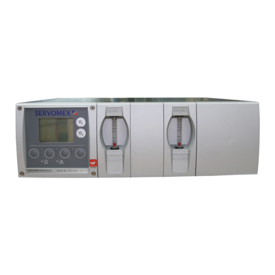
(see Section 6) and replacement of filter / scrubber elements (if fitted: see Sections 8.3, 8.4 and 8.5). Ordering options For the latest ordering options please contact your local Servomex agent or visit www.servomex.com. 05410001A / Revision 6... - Page 9 MultiExact Gas Analyser 1 – Description and definitions SERVOMEX FILTER FILTER SERVO PRO MultiExact Serial No. 05410/P0001 SERVOMEX SERVOMEX Bypass Sample Bypass Sample SERVO PRO MultiExact Serial No. 05410/P0001 Analyser with external filters Analyser with flowmeters Key Description Key Description...
- Page 10 1 – Description and definitions MultiExact Gas Analyser Key Description Key Description Regional compliance symbols ** Transducer 2 status relay connector (option) Transducer 1 sample gas inlet Transducer 2 auto val/cal connector WEEE compliance symbol (option) Transducer 2 sample gas inlet * †# Transducer 1 mA output/voltage Transducer 2 sample gas inlet...
-
Page 11: Specification
MultiExact Gas Analyser 2 – Specification SPECIFICATION WARNING The protection, accuracy, operation and condition of the equipment may be impaired if the analyser is not installed in accordance with the requirements of this and subsequent sections of the manual. General Dimensions: * Add 100 mm to length (L) if valve block is fitted length x height x width... -
Page 12: Electrical Data
2 – Specification MultiExact Gas Analyser Electrical data Electrical supply Voltage 100 to 240 Vac, 50 to 60 Hz (± 10% maximum fluctuation) Fuse rating / type T 3.15 AH / 250 V size: 20 x 5 mm Maximum power consumption 100 VA Interface signal relay ratings * 30 V (dc or ac) / 1 A... -
Page 13: Sample Gas
MultiExact Gas Analyser 2 – Specification Sample gas ☞ The sample gases must be non flammable, clean, non-corrosive, free from oil and condensates and compatible with the materials listed in Appendix A6. Paramagnetic transducer (% O Flow rate * 100 to 250 ml min Dew point 5 °C below ambient temperature (minimum) Temperature... -
Page 14: Calibration Gas
2 – Specification MultiExact Gas Analyser Calibration gas ☞ The calibration gases must be clean, non-corrosive, free from oil and condensates and compatible with the materials listed in Appendix A6. ☞ For optimum calibration results, the calibration gas flow rate/pressure should be the same as the flow rate/pressure of the gases to be sampled. - Page 15 MultiExact Gas Analyser 2 – Specification TCD transducer calibration gases High Calibration setpoint 90 – 110% of range** Low Calibration setpoint -10 – 10% of range** Minimum Calibration difference 85% of range** between low and span Low Calibration tolerance level * ±...
- Page 16 MultiExact Gas Analyser CAUTION It is recommended that sample/calibration gas flow is monitored or the flow alarm option is purchased from Servomex to ensure a representative sample is being measured for control systems. CAUTION The sample and bypass flowmeters are calibrated for use with air as the background gas.
-
Page 17: Unpack The Analyser
It is advisable that the protective covers are kept on just prior to fitting. Inspect the analyser and the other items supplied, and check that they are not damaged. If any item is damaged, immediately contact Servomex or your local Servomex agent. -
Page 18: Analyser User Interface
When you first switch on the analyser, a 'start-up screen' is displayed while the analyser carries out a self-test. The start-up screen shows the Servomex name, a 'self-test time elapsed/remaining' indicator, and messages identifying the tasks being carried out as part of the self-test. - Page 19 MultiExact Gas Analyser 4 – Analyser user interface (A) 1 measurement screen: Gas being measured Measurement units Pressure compensation indicator * Transducer number Current measurement ("1" always shown) Fault icon (see Section Alarm icon Status icon bar (see Section 5.11.1) (see Section 4.4) mA Range Software health indicator...
-
Page 20: Soft Key Legends
4 – Analyser user interface MultiExact Gas Analyser ☞ During normal analyser operation, the software health indicator continuously moves from left to right and then back again, below the status icon bar. If the indicator stops moving, this means that the analyser is not operating correctly, and you must refer to Section 9. -
Page 21: System And Measurement Status Icons
MultiExact Gas Analyser 4 – Analyser user interface Other soft key legends which are used on the various screens are as follows: Legend Meaning Function (when soft key pressed) Back Cancels the current screen and displays the previous screen in the menu structure Accept Accepts the currently selected option or data. -
Page 22: Scroll Bars
4 – Analyser user interface MultiExact Gas Analyser Scroll bars On some screens (for example, see Figure 5), there may be more options available than can be shown on the screen, and you have to scroll down the screen to view all of the options: this is identified by a scroll bar at the right-hand side of the screen. - Page 23 MultiExact Gas Analyser 4 – Analyser user interface Figure 4 – The analyser menu structure 05410001A / Revision 6...
-
Page 24: The Menu Screen
4 – Analyser user interface MultiExact Gas Analyser The menu screen ☞ Some of the menu screens referenced below may not be available: refer to the note at the start of Section 4. The menu screen provides access to other screens in the menu structure, and is displayed by pressing the soft key when the measurement screen is displayed. -
Page 25: The Settings Screen
The information screen This screen shows information (such as the analyser serial number and the version of the operating software embedded in the analyser) which is useful to the Servomex support team. Figure 7 – Typical information screen Note that the information shown on the screen will vary, depending on the analyser model. -
Page 26: Editing On-Screen Data
☞ You may be asked to provide the information from this screen to the Servomex support team; for example, as an aid to fault diagnosis. 4.10 Editing on-screen data A common method is used for editing data shown on all of the different screens. -
Page 27: Installation And Set-Up
MultiExact Gas Analyser 5 – Installation and set-up INSTALLATION AND SET-UP WARNING The analyser must be installed by a suitably skilled and competent person. The following procedure must be followed to prevent a hazard. WARNING The analyser is only suitable for installation in safe areas. CAUTION Do not install the analyser in a frame/rack or on a bench which is subject to high levels of vibration or sudden jolts. - Page 28 5 – Installation and set-up MultiExact Gas Analyser Fit the analyser (3) in the panel (5) and use nuts and bolts through the fixing holes (7) in the panel and the mounting brackets (1, 4) to secure the analyser in place.
-
Page 29: Rack With Slide Mounting
MultiExact Gas Analyser 5 – Installation and set-up 5.1.3 Rack with slide mounting Before installing the analyser, determine where you will install it in the rack enclosure. The analyser will occupy 9 rack flange cage nut positions vertically; with the bottom cage nut designated as position 1, you will need to use positions 1, 3, 4 and 7 on both the right-hand and left-hand front and rear rack enclosure flanges. - Page 30 5 – Installation and set-up MultiExact Gas Analyser Ensure that the slide opening is at the front, then loosely fit the right-hand outer slide section (5) to the front and rear slide support brackets (14, 10) and secure with the four M4 screws (4), and the nuts and washers (9, 13). Ensure that the front of the right-hand outer slide section (5) is 35 mm behind the rack enclosure front flange (16), then fully tighten the nuts (9, 13) to secure the slide section in position.
- Page 31 MultiExact Gas Analyser 5 – Installation and set-up Key Description Key Description Analyser Slide support clamp (rear) Slide inner section Slide support clamp (front) M5 pan head screws (3 off) M4 Nut, washer and locking washer (2 off) M4 counter sunk screws (4 off) Slide support bracket (front) Slide outer section M6 cage nuts (4 off)
-
Page 32: Valve Block Connections (Option)
5 – Installation and set-up MultiExact Gas Analyser 5.1.4 Valve block connections (option) Key Description Key Description Gas outlet Low cal gas inlet High cal gas inlet Sample gas inlet Figure 11 – Valve block connections (compression fittings not supplied) CAUTION To comply with EMC requirements, the valve block shall only be connected to the control relays using the supplied cable. -
Page 33: Electrical Installation
MultiExact Gas Analyser 5 – Installation and set-up Electrical Installation 5.2.1 Electrical Safety WARNING Ensure that the electrical installation of the analyser conforms with all applicable local and national electrical safety requirements. WARNING Obey the safety instructions given below when you install the analyser;... -
Page 34: Analogue Output Connections
5 – Installation and set-up MultiExact Gas Analyser 5.2.2 Analogue output connections WARNING The analogue output terminals are separated from the analyser mains circuits by reinforced insulation. The terminals must only be connected to circuits that are themselves separated from mains voltages by an isolation method that provides at least this level of protection. -
Page 35: Fault And Range Relay Connections
MultiExact Gas Analyser 5 – Installation and set-up 5.2.3 Fault and range relay connections WARNING The fault and range relay connections are separated from the analyser mains circuits by reinforced insulation. The terminals must only be connected to circuits that are themselves separated from mains voltages by an isolation method that provides at least this level of protection. -
Page 36: Alarm And Status Relay Connections (Option)
5 – Installation and set-up MultiExact Gas Analyser 5.2.4 Alarm and status relay connections (option) WARNING The alarm and status relay connections are separated from the analyser mains circuits by reinforced insulation. The terminals must only be connected to circuits that are themselves separated from mains voltages by an isolation method that provides at least this level of protection. -
Page 37: Auto Validate/Calibrate Connections (Option)
MultiExact Gas Analyser 5 – Installation and set-up 5.2.5 Auto validate/calibrate connections (option) WARNING The auto validate/calibrate board connections are separated from the analyser mains circuits by reinforced insulation. The terminals must only be connected to circuits that are themselves separated from mains voltages by an isolation method that provides at least this level of protection. - Page 38 5 – Installation and set-up MultiExact Gas Analyser Connect pins 1 and 2 to start a low calibration or initiate auto validation/ calibration (Figure 17). Connect pins 3 and 4 to start a high calibration or stop auto validation/ calibration (Figure 17). Connect pins 5 and 6 to initiate service in progress (Figure 17).
-
Page 39: Modbus Rs485 And Ethernet Connections (Option)
MultiExact Gas Analyser 5 – Installation and set-up 5.2.6 Modbus RS485 and ethernet connections (option) WARNING The digital communications terminals are separated from the analyser main circuit by reinforced insulation. The terminals must only be connected to circuits that are themselves separated from mains voltages by an isolation method that provides at least this level of protection. -
Page 40: Connect The Electrical Supply
5 – Installation and set-up MultiExact Gas Analyser 5.2.7 Connect the electrical supply WARNING Ensure that your external electrical supply outlet is isolated and locked out before you connect the conductors in the electrical supply cable. WARNING Only use the power supply cord provided with the unit. CAUTION Ensure that the analyser is suitable for use with your electrical supply voltage and frequency (refer to Section 2.3). -
Page 41: Connect The Sample/Calibration Gas Pipeline(S)
MultiExact Gas Analyser 5 – Installation and set-up Connect the sample/calibration gas pipeline(s) WARNING Sample and calibration gases may be toxic or asphyxiant: • Ensure that the external connections are leak free at full operating pressure before you use sample or calibration gases. •... -
Page 42: Switch On/Set-Up
5 – Installation and set-up MultiExact Gas Analyser ☞ For 0-10ppm CO2 or 0-500ppm CO2, on initial start-up you must switch on the electrical supply and leave the analyser to purge on low calibration gas for at least 24 hours until the reading has stabilised before calibrating the analyser. Switch on/set-up ☞... -
Page 43: Selecting The Security Level
MultiExact Gas Analyser 5 – Installation and set-up ☞ Password protection can be used to prevent adjustment of the clock by unauthorised persons, so ensuring the validity of measurement times and the 'time since last calibration' history. Figure 4 shows the options/screens which can be password-protected within the menu structure. -
Page 44: Changing Passwords
If you change a password, ensure that you record the new password somewhere safe. Otherwise, if you cannot recall the new password, you will have to contact Servomex or your local Servomex agent for assistance. Use the following procedure to change the supervisor and operator passwords: ➞... -
Page 45: Adjusting The Backlight Timer
MultiExact Gas Analyser 5 – Installation and set-up 5.4.5 Adjusting the backlight timer When the analyser is first switched on, the backlight goes on to illuminate the screen. If no soft key is pressed, the backlight will remain on for the preset 'backlight time', and will then go off. -
Page 46: Changing Regional Settings
5 – Installation and set-up MultiExact Gas Analyser 5.4.7 Changing regional settings You can configure the following analyser regional settings so that the information shown on the various screens is better suited to your local conventions: Setting Options available Language Various languages are supported Date format Day/Month/Year * or Month/Day/Year... -
Page 47: Setting Up Automatic Validation/Calibration (Option)
MultiExact Gas Analyser 5 – Installation and set-up Setting up automatic validation/calibration (option) 5.5.1 Overview of automatic validation/calibration Automatic validation operates in the same way as automatic calibration, except that the transducers are not calibrated when the low and high calibration gases have been passed through the transducers. -
Page 48: Automatic Validation/Calibration Sequence
5 – Installation and set-up MultiExact Gas Analyser • You can specify a pre-warning time, which will precede the automatic validation/calibration. During this time, the 'service in progress' status output (see Section 5.2.4) will be set; the automatic validation/calibration will then be carried out at the end of the pre-warning time. - Page 49 MultiExact Gas Analyser 5 – Installation and set-up Flushing time Specifies the flushing time (0 min 30 sec to 59 min 59 sec) Timer On (active) or off (inactive). If active the calibration or validation can be carried out regularly at a specified frequency.
- Page 50 5 – Installation and set-up MultiExact Gas Analyser Time Sample gas measurement Initiate auto calibration Service in progress (SIP) status on Pre-warning period Route calibration gas 1 into the analyser (Tx1) Inerting phase Flushing phase Auto calibration (low) Route calibration gas 2 into the analyser (Tx1) Flushing phase Auto calibration (high)
-
Page 51: Remote Calibration Or Automatic Validation/Calibration
MultiExact Gas Analyser 5 – Installation and set-up 5.5.3 Remote calibration or automatic validation/calibration Switch inputs can be set to remote calibration mode (remote cal), automatic validation/calibration mode (auto val) or disabled so the inputs will have no function, refer to Figure 17. The remote calibration function is designed for installations where the analyser is placed in an inaccessible area and the calibration gas valves are operated independently of the analyser. -
Page 52: Automatic Validation/Calibration Target And Tolerance
5 – Installation and set-up MultiExact Gas Analyser 5.5.4 Automatic validation/calibration target and tolerance ➞ Set up ➞ Auto val. Select Use the soft keys to highlight the measurement for which you want to set up the validation/calibration, then press the soft key. -
Page 53: Automatic Validation/Calibration Type And Mode
MultiExact Gas Analyser 5 – Installation and set-up Scroll down to the high target value then repeat steps 3 and 4 to set the high target high tolerance values. Figure 33 – The auto val/cal high target value screen Figure 34 – The auto val/cal high tolerance screen 5.5.5 Automatic validation/calibration type and mode Return... - Page 54 5 – Installation and set-up MultiExact Gas Analyser If you changed the pre-warning setting from 'Off' to 'On', the Auto val/cal pre-warning timer screen will then displayed (see Figure 38). Edit the displayed time as described in Section 4.10. Figure 38 – The Auto val/cal pre-warning timer screen Select 'On' or 'Off' for inerting.
-
Page 55: Automatic Validation/Calibration Timers
MultiExact Gas Analyser 5 – Installation and set-up 5.5.7 Automatic validation/calibration timers Return auto val screen (Figure 30). Select 'Timer'. Select 'On' or 'Off' for Timer. Figure 43 – The auto val/cal timer screen Scroll to the auto val/cal start date screen. -
Page 56: Calibration Linking
5 – Installation and set-up MultiExact Gas Analyser Calibration linking ☞ Calibration linking only applies to analysers configured for 2 measurements. ☞ If calibration is not linked, the alarms for each transducer will operate in accordance with their corresponding 'During Calibration' options during calibration. -
Page 57: Configuring And Using The Ma Outputs (Option)
MultiExact Gas Analyser 5 – Installation and set-up Configuring and using the mA outputs (option) 5.7.1 Overview The analyser can be supplied with a mA output for each sample gas measurement for which the analyser is configured. Each mA output provides a constantly updated output, in which the current represents the value of gas sample measurements. - Page 58 5 – Installation and set-up MultiExact Gas Analyser Parameter Values/options Range 1 low level The range 1 lowest sample measurement Range 1 high level The range 1 highest sample measurement (span) * Range 2 low level The range 2 lowest sample measurement Range 2 high level The range 2 highest sample measurement (span) * During calibration...
-
Page 59: Setting Up The Ma Output Parameters
MultiExact Gas Analyser 5 – Installation and set-up 5.7.3 Setting up the mA output parameters ☞ If auto ranging is selected, the way in which the output changes between the ranges depends on the values you have set for the range change point and the hysteresis. - Page 60 5 – Installation and set-up MultiExact Gas Analyser ☞ You cannot enter a high level value higher than 120% of the maximum measurement that the corresponding gas transducer can determine (refer to Appendix A9). ☞ The minimum differences between the low level and high levels are detailed in Appendix A9.
- Page 61 MultiExact Gas Analyser 5 – Installation and set-up If auto ranging is selected you will then need to set the range change point and the hysteresis. Figure 55 – The mA range change point screen Figure 56 – The mA range change hysteresis screen 05410001A / Revision 6...
-
Page 62: Calibrating The Ma Output
5 – Installation and set-up MultiExact Gas Analyser 5.7.4 Calibrating the mA output Use the following procedure to calibrate the mA output: ➞ Service ➞ mA output. Select Figure 57 – The mA output service screen Select the required 'Calibrate' option. Figure 58 –... -
Page 63: Configuring And Using The Voltage Outputs (Option)
MultiExact Gas Analyser 5 – Installation and set-up Configuring and using the voltage outputs (option) 5.8.1 Overview The analyser can be supplied with a voltage output for each sample gas measurement for which the analyser is configured. The output is set up in the same way as for mA, however: •... -
Page 64: Entering A Cross-Interference (X-Interference) Compensation
5 – Installation and set-up MultiExact Gas Analyser 5.9.2 Entering a cross-interference (X-Interference) compensation ☞ You can only apply cross-interference compensation to O purity or control measurements. ☞ X-Interference compensation is disabled during calibration, and is not applied to the values shown in Figure 74. All other outputs (that is, serial or mA outputs) remain compensated. - Page 65 MultiExact Gas Analyser 5 – Installation and set-up ☞ When you select display units other than the measurement default units, you must also enter the units conversion factor: refer to Appendix A5 to determine the units conversion factor for your specific application. ☞...
-
Page 66: Configuring The Measurement Alarms
5 – Installation and set-up MultiExact Gas Analyser 5.11 Configuring the measurement alarms 5.11.1 Alarm modes and levels Two separate measurement alarms are available for each sample gas measurement for which the analyser is configured, and you can configure each alarm to operate in one of three modes: Alarm mode Operation... - Page 67 MultiExact Gas Analyser 5 – Installation and set-up ➞ Set up. Select Select the required transducer and alarm. Figure 63 – The alarm set up screen Select the required mode (none, low or high), then press the soft key. Figure 64 – The alarm mode screen Scroll up or down to edit the appropriate settings (using the method described in Section 4.10): •...
-
Page 68: Latching/Non-Latching Alarms
5 – Installation and set-up MultiExact Gas Analyser 5.11.2 Latching/non-latching alarms You can configure each of the two measurement alarms to be either latching or not latching: ➞ Set up. Select Alarm setting Meaning Latching Once the alarm condition has been activated, the alarm condition remains activated (even if subsequent sample measurements would not trigger the alarm) until the alarm is manually unlatched Not latching... -
Page 69: Viewing The Measurement Alarm Status
MultiExact Gas Analyser 5 – Installation and set-up For example: • If a 'low' alarm has an alarm level of 98% and a hysteresis level of 1%, the alarm will be activated when a sample measurement is < 98%, and the alarm will not be deactivated until a sample measurement is >... -
Page 70: Setting Up The Flow Alarm (Option)
5 – Installation and set-up MultiExact Gas Analyser 5.12 Setting up the flow alarm (option) The flow alarm (utilising Flowcube [F ] technology) option measures the sample flow through a measurement transducer and allows the user to configure two low flow alarms and one high flow alarm. - Page 71 MultiExact Gas Analyser 5 – Installation and set-up Scroll to the low flow level 2 screen and set the activation level for low flow alarm 2. Figure 69 – The low flow level 2 screen Scroll to the low flow 1 status screen and set the status type to be reported on low flow alarm 1 activation.
-
Page 72: Calibration
6 – Calibration MultiExact Gas Analyser CALIBRATION CAUTION During calibration of O purity, O control, 0-10ppm CO, 0-10ppm CO 0-500ppm CO , 0-20ppm N O or 0-50ppm CH measurements it is good practice to perform a low (Lo) calibration followed by a high (Hi) calibration. However, a single point calibration is often sufficient (see Appendix A10). - Page 73 MultiExact Gas Analyser 6 – Calibration supply to the analyser sample gas inlet. ➞ Calibrate. Select ☞ On a 2-measurement analyser, this screen will show one 'Lo' and one 'Hi' calibration for each of the two measurements. Figure 73 – The calibrate screen Note that the "9999d"...
-
Page 74: Automatic Validation/Calibration
6 – Calibration MultiExact Gas Analyser Press the soft key to display the measurement screen again. Automatic validation/calibration 6.2.1 Initiating an automatic validation/calibration ☞ You must have set up the parameters/options as described in Section 5.5.2 before you initiate an automatic validation/calibration. ☞... -
Page 75: Automatic Validation/Calibration Status Indications
MultiExact Gas Analyser 6 – Calibration 6.2.2 Automatic validation/calibration status indications During an automatic validation/calibration: • A 'service in progress' icon ( ) is shown on the measurement screen, if displayed. • The calibration screen, if displayed, (pre-warning and inerting phase off) will be updated to show the current phase and the gas being used, as shown in Figure 78 to Figure 80. -
Page 76: Stopping An Automatic Validation/Calibration
6 – Calibration MultiExact Gas Analyser Figure 81 – The auto val/cal failed screen 6.2.3 Stopping an automatic validation/calibration ☞ If you stop an automatic validation/calibration after the pre-warning phase, the inerting phase (if active) and the final flushing phase will always be completed. To stop an automatic validation/calibration which is in progress, close the stop auto val switch input on the appropriate interface connection (see Section 5.2.5) or use modbus command see Appendix A3. -
Page 77: Viewing Validation/Calibration History
MultiExact Gas Analyser 6 – Calibration 6.2.4 Viewing validation/calibration history You can use the following procedure to display the 100 most recent validation/ calibration points: ➞ Calibrate ➞ View history. Select This screen shows the target value (T) and the actual measurement reading (R) before val/cal was carried out. -
Page 78: Calibrating The Pressure Transducer (O Purity Only)
6 – Calibration MultiExact Gas Analyser Calibrating the pressure transducer (O purity only) CAUTION On a pressure driven analyser, do not exceed the specified maximum calibration gas inlet pressure, and on a flow driven analyser, do not exceed the specified maximum flow rate. If you do, the pressure transducer may be damaged and the analyser may not operate correctly. -
Page 79: Calibrating The Flow Alarm (Option)
MultiExact Gas Analyser 6 – Calibration If low calibration was successful the screen should display as shown in Figure 86. Adjust valve that measurement reading is between 105 and 115% O Figure 86 – Pressure high Adjust your calibration gas supply so calibration screen that the flow rate is the same rate as noted in Step 6. -
Page 80: General Operation
7 – General operation MultiExact Gas Analyser GENERAL OPERATION CAUTION Sample and calibration gases must be as specified in Sections 2.4 and 2.5. If the pressure/flow rates are outside the ranges specified in Sections 2.4 and 2.5, you must regulate the gases externally, before they enter the analyser. -
Page 81: Pressure Compensation (O Purity And Control Only)
MultiExact Gas Analyser 7 – General operation Scroll to the relay override screen (Figure 90). Select the 'Yes' option, then press soft key. The relay outputs will now be set to the selected override state, and you can use your control/monitoring equipment Figure 90 –... -
Page 82: Viewing Pressure Effected Measurements (Option)
7 – General operation MultiExact Gas Analyser 7.2.3 Viewing pressure effected measurements (option) When pressure compensation is on, use the following procedure to view simultaneous pressure compensated and uncompensated measurements: ➞ View ➞ Pressure. Select On this screen: • The 'Pre comp' value sample... -
Page 83: Checking The Ma Output (Option)
MultiExact Gas Analyser 7 – General operation Checking the mA output (option) If required, use the following procedure at any time to perform a check on a mA output: ➞ Service ➞ mA output. Select Select the required 'Override' option. Edit the displayed override value as described in Section 4.10. -
Page 84: Routine Maintenance
8 – Routine maintenance MultiExact Gas Analyser ROUTINE MAINTENANCE WARNING The analyser must be maintained by a suitably skilled and competent person. WARNING Do not open or attempt to open the analyser yourself. If you do, you will invalidate any warranty on the analyser, and the analyser may not operate safely or provide accurate measurements. - Page 85 MultiExact Gas Analyser 8 – Routine maintenance If you think that an electrical supply fuse has failed, use the following procedure to inspect the fuses and replace it if necessary: Refer to Figure 95. Remove the fuse holder (3) from the electrical supply connector (1) on the rear of the analyser.
-
Page 86: Inspecting The Optional Filter Element (O Purity / Control Only)
8 – Routine maintenance MultiExact Gas Analyser Inspecting the optional filter element (O purity / control only) If you only use the analyser on applications which use clean, dry gases, an inlet filter may not be required. If however, your application requires a filter, it can be easily checked. -
Page 87: Inspecting The Filter Element (Co / Co / N O / Ch Trace Only)
MultiExact Gas Analyser 8 – Routine maintenance Inspecting the filter element (CO / CO O / CH trace only) If you only use the analyser on applications which use clean, dry gases, you will only need to inspect the inlet filter element every 3 months. On other applications, we recommend that you inspect the inlet filter element more frequently. -
Page 88: Co 2 Scrubber
If the T90 – T100 response degrades significantly from the performance observed when the analyser was commissioned, then this may indicate that the scrubber requires changing. Contact Servomex or your local Servomex agent for instruction on how the scrubber can be changed. 8.5.2 For 0-500ppm CO... -
Page 89: Preventative Maintenance
SERVOSURE report. Note that you will always be informed in advance if any repairs or new parts are required for your analyser. Contact Servomex or your local Servomex agent to arrange for a preventative maintenance contract. 05410001A / Revision 6... -
Page 90: Fault Finding
9 – Fault finding MultiExact Gas Analyser FAULT FINDING Fault, maintenance required and SIP statuses 9.1.1 Status definitions The status definitions are as follows: • Fault – A serious fault has been detected. • Maintenance required – A maintenance required status has been raised, the analyser requires attention. - Page 91 Section 6, also check calibration gas has been allowed to flow through the analyser for the recommended time. If the fault persists, contact Servomex or your local Servomex agent for assistance. Code fault Contact Servomex or your local Servomex agent for assistance.
- Page 92 Communication fail Turn the analyser off, and then turn it on again. If the fault message is then displayed again, contact Servomex or your local Servomex agent for assistance. Database fault Turn the analyser off, and then turn it on again. If...
- Page 93 Ensure that the electrical cabling connected to the analyser is not open circuit. Turn the analyser off, and then turn it on again. If the fault persists, contact Servomex or your local Servomex agent for assistance. mA not detected Contact Servomex or your local Servomex agent for assistance.
- Page 94 Transducer error Ensure that you are using the analyser in the specified operating conditions (refer to Section 2). If the fault persists, contact Servomex or your local Servomex agent for assistance. Transducer warming Infra-red only, transducer is warming after power on, measurement should be treated with caution while status is active.
- Page 95 Message Measurement Recommended actions screen icon Tx incorrect type Contact Servomex or your local Servomex agent for assistance. Tx Maintenance Check that the sample gas concentration is not higher than the transducer full scale range. Recalibrate (both low and high) as described in Section 6.
-
Page 96: Viewing Messages
9 – Fault finding MultiExact Gas Analyser Viewing messages 9.2.1 Active messages ➞ Status ➞ Active. Select Each message status screen shows: • Date and time of message • The message type ("Fault", "Maintenance rqd" or "Service in Progress") • The message itself. Figure 98 –... -
Page 97: Diagnostics
MultiExact Gas Analyser 9 – Fault finding Diagnostics The trace measurements have diagnostic capabilities. The displayed diagnostic codes can be interrogated by the Servomex Service Team to determine the problem with the transducers. ☞ Diagnostics are only enabled for the trace O... -
Page 98: General Fault Finding
For general analyser fault finding, refer to the table on the following pages. If you have read through the table and still cannot rectify a fault, or cannot identify the cause of a fault, contact Servomex or your local Servomex agent for assistance. Fault symptom Recommended actions The fault LED is on. - Page 99 MultiExact Gas Analyser 9 – Fault finding Fault symptom Recommended actions Analyser measurements are not as Check that the correct display units have been expected. selected, and that the units conversion factor has been correctly entered (see Section 5.10). If you are using pressure compensation, check that the pressure transducer has been correctly calibrated and is switched on (see Section 6.3).
- Page 100 If you have configured the mA output to jam high or 21.5 mA. jam low, check whether a fault condition exists (see Section 5.7). Otherwise, contact Servomex or your local Servomex agent for assistance. The milliAmp output is not as Ensure that the electrical cabling connected to the expected.
-
Page 101: Storage And Disposal
Refer to Appendix A7 for disposal requirements in accordance with the WEEE Directive within the EC. ☞ If you send the analyser to Servomex or your local Servomex agent for disposal, it must be accompanied by a correctly completed decontamination certificate. -
Page 102: Spares
If you do, you can damage the analyser and invalidate any warranty. The standard spares available for the analyser are shown below. You can order these spares from Servomex or your Servomex agent. Spare Part Number... -
Page 103: Rs232 Connection Details
MultiExact Gas Analyser Appendix RS232 CONNECTION DETAILS WARNING Ensure that the electrical installation of any equipment connected to the analyser conforms with all applicable local and national electrical safety requirements. WARNING The RS232 output is separated from the analyser mains circuits by reinforced insulation. -
Page 104: A1.2 Connecting The Analyser To A Pc
Appendix MultiExact Gas Analyser A1.2 Connecting the analyser to a PC The analyser can be directly connected to the 9-way 'D' type serial port (usually designated "COM1" or "COM2") on your PC. Use a compatible 9-way 'D Null Modem' cable (with a recommended maximum length of 3 metres), with female-to-female connectors. -
Page 105: A1.4 Capturing Data Using Windows And Hyper Terminal
MultiExact Gas Analyser Appendix ® A1.4 Capturing data using Windows and Hyper Terminal™ If a network option is installed (Modbus or Profibus) the communications type needs to be selected as "Serial Output". ➞ Set up ➞ Comms type. Select Select "Serial output". If you use one of the Windows operating systems, HyperTerminal is probably already installed on your PC. -
Page 106: A1.5 Configuration Transfer
Appendix MultiExact Gas Analyser A1.5 Configuration transfer If you are setting up multiple units and you want to use the same configuration settings in each analyser, you can transfer configuration data from one unit to another, either via a computer or directly with one another. This way all the user setable configurations: calibration tolerances and targets;... - Page 107 At the end of the transfer the number of configuration items successfully read in and the total number of lines read will be displayed. The terminal will show something similar to the following: ####################### # SERVOMEX 1.0 # 2008/12/01 11:46 # 05000A1/00001 # 05000-cu0_13...
- Page 108 Appendix MultiExact Gas Analyser If a line is not correct a question mark will be placed after it, such as in the following file: ####################### # SERVOMEX 1.0 # 2008/12/01 11:46 # 05000A1/00001 # 05000-cu0_13 ####################### 04000011000400000001E6 04000003000400000002F3 04000013000400000002E3 19000006000442C80000D3...
-
Page 109: A2 Serial Output Formats
MultiExact Gas Analyser Appendix APPENDIX SERIAL OUTPUT FORMATS The serial output consists of a number of measurement lines, one line for each update. Each measurement line consists of a number of elements, separated from each other by the delimiter string " ; " (space, semicolon, space), in the following format: <date>... -
Page 110: A3 Implementation Guide For Modbus Communications (Option)104
Appendix MultiExact Gas Analyser APPENDIX IMPLEMENTATION GUIDE FOR MODBUS COMMUNICATIONS (OPTION) A3.1 Introduction This appendix details the implementation and use of the Modbus protocol in the MultiExact analyser. A3.2 References Document "MODBUS over Serial Line Specification & Implementation guide V1.0 Nov 02"... -
Page 111: A3.4 Supported Function Codes
MultiExact Gas Analyser Appendix A3.4 Supported function codes For simplicity, only the following function codes will be supported. Function Description Usage Read coils Read calibration status, pump state, etc. Read discrete inputs Read faults and alarm states. Read holding registers Read settings. -
Page 112: Floating Point Numbers
Appendix MultiExact Gas Analyser A3.7 Floating point numbers Floating point numbers (e.g. 12.34, –1012.32, etc.), are digitally represented using the IEEE–754 format. Single precision floating point numbers are used throughout and they require 32 bits of data. Since a Modbus register holds 16 bits it takes 2 registers to represent a floating point number. - Page 113 MultiExact Gas Analyser Appendix The following table shows the assignment for transducer 1. Each register provides 2 bytes of data. Register Name Comments 101 – 102 Measurement As seen on the measurement display. Floating point number. 103 – 104 Filtered Basic measurement, filtered.
-
Page 114: A3.10 System Fault Mapping
Appendix MultiExact Gas Analyser A3.10 System Fault Mapping Read-only access to system fault information will be provided in a block of 100 registers. These can be accessed as discrete inputs using function code 02 or as input registers using function code 04. Reading them as discrete inputs provides a simple bit result for each, 0 for off and 1 for on. -
Page 115: A3.11 Transducer Fault And Alarm Mapping
MultiExact Gas Analyser Appendix A3.11 Transducer fault and alarm mapping Read-only access to transducer fault and alarm information will be provided in a block of 100 registers and coils. These can be accessed as discrete inputs using function code 02 or as input registers using function code 04. Reading them as discrete inputs provides a simple bit result for each, 0 for off and 1 for on. - Page 116 Appendix MultiExact Gas Analyser Register Name Comments 1112 Communication fail Transducer not responding. 1113 Incorrect transducer type Incorrect type of transducer fitted. 1114 Transducer not detected Transducer is unplugged or broken. 1115 Low calibration fail Auto cal low failed. 1116 High calibration fail Auto cal high failed.
- Page 117 MultiExact Gas Analyser Appendix Register Name Comments 1137 Transducer calibration Calibration mode is active. mode 1138 Auto validation/calibration. Sequence is in progress. 1139 mA service in progress Calibration or override in progress. 1140 Volt service in progress Calibration or override in progress. 1141 Pressure service in progress Calibration in progress.
-
Page 118: A3.12 System Set-Up Mapping
Appendix MultiExact Gas Analyser A3.12 System set-up mapping System data will be available with read-write access in blocks of holding registers. This data can be read with function code 03 and written with function codes 06 and 16. Register Name Comments Clock Year... - Page 119 MultiExact Gas Analyser Appendix The following table shows the assignment for transducer 1. Each register provides 2 bytes of data. Register Name Comments Analogue Output 101 – 102 Range 1 low Float. 103 – 104 Range 1 high Float. 105 – 106 Range 2 low Float.
- Page 120 Appendix MultiExact Gas Analyser Register Name Comments Start year 0 – 99 Start month 1 – 12. Start date 1 – 31. Start hour 0 – 23. Start minute 0 – 59. Repeat hour Integer. Pressure Compensating 0 = no, 1 = yes. Alarm set up Alarm 1 mode 0 = none, 1 = low, 2 = high.
-
Page 121: System Control
MultiExact Gas Analyser Appendix A3.14 System control System control will be provided using a block of coils that can be written to using function code 05. Reading the same coils with function code 01 provides status information. Coil Name Comments Floating point order Changes the order of the Modbus registers when dealing with 32-bit floating point numbers. - Page 122 Appendix MultiExact Gas Analyser The coils for transducer 1 are shown in the following table: Coil Name Comments Measurement Calibration mode on/off 0 = off (normal), 1 = on (alarms masked, jamming etc). Write 1 to turn calibration mode on. Low calibration gas 0 = sample gas, 1 = low calibration gas.
-
Page 123: Configuring The Modbus Parameters (Option)
MultiExact Gas Analyser Appendix APPENDIX CONFIGURING THE MODBUS PARAMETERS (OPTION) If your analyser has the Modbus output (either RS485 or Ethernet), you must configure the communications parameters to suit the requirements of the network to which you have connected the analyser. The cable connections are shown in Section 5.2.6. - Page 124 Appendix MultiExact Gas Analyser Use the soft keys to select the next parameter. Parity, this can be none, even or odd. Use the soft keys to select the correct value. Figure A8 – Comms parameters parity screen 05410001A / Revision 6...
-
Page 125: Tcp (Ethernet)
MultiExact Gas Analyser Appendix A4.2 TCP (Ethernet) ➞ Settings ➞ Comms parameters. Select The first screen requests the IP address, (always communicates in RTU mode). Use the soft keys to select the correct value. Figure A9 – Comms parameters IP address screen ☞... -
Page 126: Display Unit Conversion Factors
Appendix MultiExact Gas Analyser APPENDIX DISPLAY UNIT CONVERSION FACTORS When you select display units as described in Section 5.10, you must ensure that you also enter the correct units conversion factor, as shown in the table below: † To convert use the units applicable from *... -
Page 127: Sample Wetted Materials
MultiExact Gas Analyser Appendix APPENDIX SAMPLE WETTED MATERIALS The materials of the parts of the analyser in contact with the sample and calibration gases are listed below. These materials have a wide range of chemical compatibility and corrosion resistance. Oxygen Purity Measurement 303 st steel Viton Polypropylene... - Page 128 Appendix MultiExact Gas Analyser TCD measurements 316 st steel Viton 310 st steel Borosilicate glass Platium Platium iridium alloy Alumina Nickel iron Sealing glass Polysulphone Duralumin Polycarbonate Glass fibre Flow meter Borosilicate glass Duralumin 316 st steel Flow Alarm Platinum iridium alloy Glass Stabilised zirconia 316 st steel...
-
Page 129: Disposal In Accordance With The Waste Electrical And Electronic Equipment (Weee) Directive
WEEE Directive, contact Servomex or your local Servomex agent. ☞ If you send the analyser to Servomex or your local Servomex agent for disposal, the analyser must be accompanied by a correctly completed decontamination certificate. -
Page 130: Compliance And Standards Information
• The analyser has been assessed to IEC 61010–1 for electrical safety including any additional requirements for US and Canadian national differences. • Servomex Group Ltd is a BS EN ISO 9001 and BS EN ISO 14001 certified organisation. 05410001A / Revision 6... -
Page 131: Performance Data
MultiExact Gas Analyser Appendix APPENDIX PERFORMANCE DATA A9.1 purity measurement ☞ The display indication given below is the default indication. You can configure the analyser to provide other display indications (see Section 5.10). ☞ Performance data has been determined in accordance with EN61207. Display indication Measured volume % O Full scale range... -
Page 132: Performance Data: O
Appendix MultiExact Gas Analyser A9.2 Performance data: O control measurement ☞ The display indication given below is the default indication. You can configure the analyser to provide other display indications (see Section 5.10). ☞ Performance data has been determined in accordance with EN61207. Display indication Measured volume % O Full scale range... -
Page 133: Trace Measurement
MultiExact Gas Analyser Appendix A9.3 Performance data: O trace measurement ☞ The display indication given below is the default indication. You can configure the analyser to provide other display indications (see Section 5.10). ☞ Performance data has been determined in accordance with EN61207. Display indication ppm O Full scale range... -
Page 134: Performance Data: 0-10Ppm Co
Appendix MultiExact Gas Analyser A9.4 Performance data: 0-10ppm CO measurement ☞ The display indication given below is the default indication. You can configure the analyser to provide other display indications (see Section 5.10). ☞ Performance data has been determined in accordance with EN61207. Display indication ppm CO Full scale range... -
Page 135: Performance Data: 0-500Ppm Co
MultiExact Gas Analyser Appendix A9.5 Performance data: 0-500ppm CO measurement ☞ The display indication given below is the default indication. You can configure the analyser to provide other display indications (see Section 5.10). ☞ Performance data has been determined in accordance with EN61207. The performance specification for 0-50ppm range is applicable when the ☞... - Page 136 Appendix MultiExact Gas Analyser ¹ Calibrated using 500ppm CO span gas ² Calibrated using 50ppm CO span gas for change of 0-10ppm at 400 ml min † For a 200 to 500 ml min change in sample gas flow rate. ‡...
-
Page 137: Performance Data: 0-10Ppm Co Measurement
MultiExact Gas Analyser Appendix A9.6 Performance data: 0-10ppm CO measurement ☞ The display indication given below is the default indication. You can configure the analyser to provide other display indications (see Section 5.10). ☞ Performance data has been determined in accordance with EN61207. Display indication ppm CO Full scale range... -
Page 138: Performance Data: 0-20Ppm N
Appendix MultiExact Gas Analyser A9.7 Performance data: 0-20ppm N O measurement ☞ The display indication given below is the default indication. You can configure the analyser to provide other display indications (see Section 5.10). ☞ Performance data has been determined in accordance with EN61207. Display indication ppm N Full scale range... -
Page 139: Performance Data: 0-50Ppm Ch
MultiExact Gas Analyser Appendix A9.8 Performance data: 0-50ppm CH measurement ☞ The display indication given below is the default indication. You can configure the analyser to provide other display indications (see Section 5.10). ☞ Performance data has been determined in accordance with EN61207. For either nitrogen or helium background gas, transducer to be calibrated using the chosen background gas. -
Page 140: Performance Data: Tcd
Appendix MultiExact Gas Analyser A9.9 Performance data: TCD ☞ The display indication given below is the default indication. You can configure the analyser to provide other display indications (see Section 5.10). ☞ Performance data has been determined in accordance with EN61207. Gas and Ranges available ... -
Page 141: Performance Data: Flow Alarm
MultiExact Gas Analyser Appendix A9.10 Performance data: flow alarm Resolution ± 1% of calibrated range Intrinsic Error ± 10% of calibrated range Ambient temperature coefficient ± 7% of calibrated range per 10 °C Response time < 20 seconds (T60 – 100% flow to 0% flow) Acceptable background gases Nitrogen, Oxygen, Carbon Dioxide, Carbon Monoxide, Argon and Air... -
Page 142: Recommended Calibration Periods
Appendix MultiExact Gas Analyser A10 RECOMMENDED CALIBRATION PERIODS Gas transducer Low cal High cal CO, CO O, CH Trace Weekly 3 monthly Purity * 2 monthly Monthly Control 2 weekly Monthly Trace Monthly 6 monthly Monthly Monthly Flow alarm Annually Annually * Calibrate the pressure compensation annually. - Page 143 MultiExact Gas Analyser Appendix A11 CROSS INTERFERENCE OFFSETS (FOR PARAMAGNETIC TRANSDUCERS) Pure Gas Formula Molar Cross interference offsets mag.susc Control = 20 °C Purity = 60 °C x 10 20 °C 50 °C 60 °C 110 °C Acetaldehyde –22.70 –0.31 –0.34 –0.35 –0.40...
- Page 144 Appendix MultiExact Gas Analyser Pure Gas Formula Molar Cross interference offsets mag.susc Control = 20 °C Purity = 60 °C x 10 20 °C 50 °C 60 °C 110 °C Enflurane (Ethrane) –80.10 –1.97 –2.17 –2.24 –2.57 Ethane –26.80 –0.43 –0.47 –0.49 –0.56...
- Page 145 MultiExact Gas Analyser Appendix Pure Gas Formula Molar Cross interference offsets mag.susc Control = 20 °C Purity = 60 °C x 10 20 °C 50 °C 60 °C 110 °C Neon –6.70 0.15 0.17 0.17 0.20 Nitric oxide 1461.00 42.56 42.96 42.94 41.62...
Need help?
Do you have a question about the SERVOPRO MultiExact and is the answer not in the manual?
Questions and answers