
Related Manuals for Servomex SERVO PRO 14440D1


Summary of Contents for Servomex SERVO PRO 14440D1
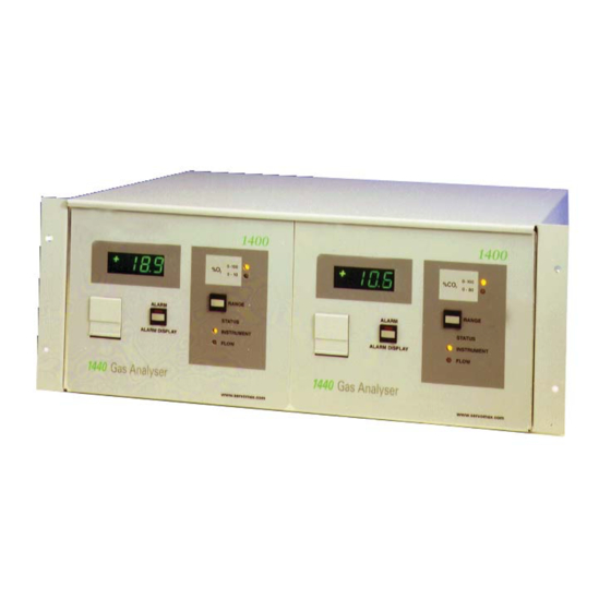
- Page 1 SERVOPRO 1440D1 Light Industrial Gas Analyser Service Manual Part Number: 01440002D Revision: Language: UK English...
- Page 2 This page intentionally blank...
- Page 3 01440D1 Light Industrial Gas Analyser Service Manual Ref.: 01440/002D/5 Order as part No. 01440002D...
- Page 4 This page intentionally blank...
-
Page 5: Table Of Contents
Table of Contents INTRODUCTION..........1.1 1.1 Scope of this Manual . - Page 6 Table of Contents 01440D Light Industrial Gas Analyser Service Manual.
- Page 7 List of Tables Table 2.1 Requirements for Sample Conditions..... . . 2.2 Table 2.2 SW3 Switch Settings ........2.12 Table 3.1 Spares for Normal Operation .
- Page 8 List of Tables 01440D Light Industrial Gas Analyser Service Manual.
- Page 9 List of Figures Figure 2.1 Cell Replacement ........2.4 Figure 2.2 Transducer Pot Adjustment .
- Page 10 List of Figures 01440D Light Industrial Gas Analyser Service Manual.
-
Page 11: Introduction
INTRODUCTION Scope of this Manual This manual covers the servicing of the Servomex 1440D series of gas analysers. This range of analysers can measure up to two gases, based on one of two measurement principles; a Servomex Single Beam Single Wavelength (SBSW) infrared transducer and a Servomex paramagnetic oxygen transducer. - Page 12 • The electrical power used in this equipment is at a voltage high enough to endanger life. Trained personnel should only perform servicing. Service training is available from Servomex. • Before carrying out servicing or repair the equipment should be disconnected from the electrical power supply.
-
Page 13: Repair
REPAIR Test Equipment and Tools The following test equipment and tools should be available to personnel responsible for maintenance and calibration of the analyser. • Volt/ohm/milli-amp meter of high input impedance, resolution 0.1mV. • Flat blade screwdriver, 6mm width. • Soldering iron 25W. -
Page 14: Sample Condition Requirements
Sample condition requirements Table 2.1 Requirements for Sample Conditions Dew Point At least 5°C below ambient temperature. Temperature Nominally at ambient temperature. Inlet / Outlet 01440D1STD connections 6.4mm (1/4”) OD tube. 01440D1STD + Note: do not restrict analyser 01440D1FTX 3.2mm (1/8”) OD tube. vent 01440D1STD 1 to 10psig (7 to 70kPag). -
Page 15: Servicing The Oxygen Transducer
Servicing the Oxygen Transducer WARNING • The opening of covers or removal of parts, except those to which access can be gained by hand, may expose electrical terminals. Ensure power is disconnected before working on the analyser. NOTE • Due to the strong magnetic field, which exists around the transducer, it is advisable to remove wristwatches if worn when servicing the oxygen transducer. -
Page 16: Replacement Of The Measuring Cell
The pipe from the outlet of the flow sensor, if fitted, goes to the upper gas connector on the cell. Ensure pipework is leak tight. See Section 2.13.1 or 2.13.2. Calibrate the analyser and check both the analogue output and display reading. - Page 17 Connect a nitrogen supply to the analyser, flow or pressure rates as per section 2.2. Ensure the electrical safety of all parts and power-up the analyser. SETTING THE ZERO (follows on from cell change procedure) Set the ZERO on the front panel to mid point (5 turns from either end).
-
Page 18: Adjusting The Transducer Gain
2.3.3 Adjusting the Transducer Gain It may be necessary to adjust the Span of the transducer if the altitude of use is greater than about 1200m (4000ft) above sea level. Carefully remove foam cover from transducer. Adjust the FINE SPAN pot on the top of the transducer fully clockwise. -
Page 19: Servicing The Infrared Transducer
The Infrared transducer in the analyser is non-field serviceable. In the unlikely event of failure, the transducer should be removed by following the procedure below and returned to Servomex for repair or replacement. A list of the IR transducers available is given in Section 3.4. -
Page 20: Checking The Analogue Outputs And Display
Transducer pots must be wound fully clockwise, reference Figure 2.2. SET SPAN AND ZERO FULLY CLOCKWISE Figure 2.2 Transducer Pot Adjustment Checking the Analogue Outputs and Display. NOTE • Calibration gas accuracy must be taken into consideration when setting the zero and span. The figures in the following steps assume pure N and either air (for oxygen) or 100% FULL SCALE (Infra-red transducers) span gas. -
Page 21: Checking The Span
If not, check for correct signal and supply voltages at the connector to the instrument display module. If these are correct but the instrument display does not read correctly, the display module may need to be replaced. Note: There is no ‘zero’ adjustment for the display module itself. -
Page 22: Replacing The Flow Sensor (01800925)
Replacing the Flow Sensor (01800925) Unscrew both wires from TB4 on relay and output PCB (01420906). Disconnect inlet and outlet tubes. Unscrew flow sensor from rear panel assembly. Installation is reverse of the removal process. (Reconnect to TB4) The pipe from the AFCD goes to the inlet on the flow sensor. Ensure pipework is leak tight. -
Page 23: Replacing The Relay/Output Pcb (01420906)
Replacing the Relay/Output PCB (01420906) Disconnect the flow sensor wires from TB4 and undo the four hexagonal fixing sets located adjacent to the 15 way ‘D' connectors. Disconnect the lower 34 way ribbon connector from the front panel PCB. Disconnect the 16 way ribbon connector at the transducer. The Relay/Output PCB may now be replaced, installation is the reverse of the removal process, ensure all connections are remade (including the link across TB4, 01440D1FTX only). -
Page 24: Replacing The Front User Interface Pcb (01420904)
2.10 Replacing the Front User Interface PCB (01420904) Remove the main control PCB, refer to section 2.9. Disconnect the display ribbon cable. Undo the five screws which retain the PCB. Before installing new control PCB, transfer the switch settings for the display (reference Table 2.2 and Figure 2.4). -
Page 25: Replacing The Led Front Panel Display (2553-7332)
ORANGE BROWN BROWN ORANGE Figure 2.4 Component Layout, Front Panel PCB (01420904B) 2.11 Replacing the Led Front Panel display (2553-7332) Remove the front panel PCB’s, reference sections 2.9 and 2.10. Undo the four corner screws on the LED module to replace. 2.12 Replacing the infra-red Interface PCB (01415930) Remove the two M4 screw holding down the interface PCB, 01415930. -
Page 26: Replacing The Internal Pump (S1420940)
2.13 Replacing the Internal Pump (S1420940) Disconect the pump switch at the front panel of the analyser. Remove the Transducer as described in section 2.3.1. Cut the cable ties holding down the pump and lever the pump and pads off the tranducer mounting bracket. -
Page 27: 01440D1Std
2.14.2 01440D1STD Follow the plumbing flow schematic shown in Figure 2.6. CELL FLOW SENSOR A.F.C.D BACK PRESSURE REGULATOR (OPTIONAL) RESTRICTOR REQUIRED FOR BACK PRESSURE REGULATOR OPTION Figure 2.6 01440D1STD Plumbing Schematic Leak test by connecting together the sample 'IN' and sample 'OUT' gas connections and connect a water manometer to them. -
Page 28: Figure 2.7 Interconnecting Wiring - 01440D1Std Oxygen Analyser
Figure 2.7 Interconnecting Wiring - 01440D1STD Oxygen Analyser 2.16 01440D Light Industrial Gas Analyser Service Manual. -
Page 29: Figure 2.8 Interconnecting Wiring - 01440D1Std Carbon Dioxide Analyser
Figure 2.8 Interconnecting Wiring - 01440D1STD Carbon Dioxide Analyser 01440D Light Industrial Gas Analyser Service Manual. 2.17... -
Page 30: Figure 2.9 Interconnecting Wiring - 01440D1Ftx Infra-Red Analyser
Figure 2.9 Interconnecting Wiring - 01440D1FTX Infra-Red Analyser 2.18 01440D Light Industrial Gas Analyser Service Manual. -
Page 31: Figure 2.10 Interconnecting Wiring - 01440D1Ftx Oxygen Analyser
Figure 2.10 Interconnecting Wiring - 01440D1FTX Oxygen Analyser 01440D Light Industrial Gas Analyser Service Manual. 2.19... -
Page 32: Figure 2.11 Circuit Diagram, Front Panel Pcb 01420904B
Figure 2.11 Circuit Diagram, Front Panel PCB 01420904B 2.20 01440D Light Industrial Gas Analyser Service Manual. -
Page 33: Figure 2.12 Circuit Diagram, Front Panel Pcb 01420904B
Figure 2.12 Circuit Diagram, Front Panel PCB 01420904B 01440D Light Industrial Gas Analyser Service Manual. 2.21... -
Page 34: Figure 2.13 Output Connections
Figure 2.13 Output Connections 2.22 01440D Light Industrial Gas Analyser Service Manual. -
Page 35: Spare Parts List
SPARE PARTS LIST WARNINGS • 01440D1FTX and 01440D1STD spares must be supplied by Servomex to comply with personnel safety requirements and to maintain performance specification. The recommended quanitity of spares to be held in stock, is a guide only. The exact... -
Page 36: Table 3.2 Spares For General Use
The following spares are also available for the analyser. Table 3.2 Spares for General Use Recommended qty. Part Description No. of analysers Number S1420904B Front ‘switching’ PCB. 2726-4119 Span or zero potentiometer. S1420915 Control PCB. S1420906 Alarm relay PCB. 210198 Power supply Unit S1440922 Power supply Assembly... -
Page 37: Table 3.3 Spares Infrared Transducers
Table 3.3 Spares Infrared Transducers Recommended qty. Part Spare Pipe- Description work Kit No. of analysers Number 01520709 0 - 0.25% CO transducer. S1420943 01520708 0 - 0.5% CO transducer. S1420943 01520707 0 - 1% CO transducer. S1420944 01520706 0 - 2.5% CO transducer. -
Page 38: Drawings Incluced In The Manual
Table 3.4 Spare for Oxygen Transducer Recommended qty. Part Description No. of analysers Number 01158000 Oxygen Transducer 00325000 Measuring Cell Drawings Incluced in the Manual Circuit Diagram of Control Board 01422911: Relevant drawing 01422/111, is enclosed. 01440D Light Industrial Gas Analyser Service Manual.
Need help?
Do you have a question about the SERVO PRO 14440D1 and is the answer not in the manual?
Questions and answers