Table of Contents
Advertisement
Quick Links
www.ti.com
User's Guide
ULC1001-DRV290x Evaluation Module
Texas Instruments created the Ultrasonic Lens Cleaning (ULC) system for removing water, ice, or other
contaminants from automotive, security, and industrial lens systems. Ultrasonic Lens Cleaning improves visibility
by efficiently clearing water, ice, and some contaminants. For some use cases, Ultrasonic Lens Cleaning
eliminates the need for washer tubes, spray nozzles, or wipers. The ULC System is an electromechanical
system composed of a piezo based lens cover or lens system, housing, and ULC1001-DRV290x EVM. The
ULC1001-DRV290x EVM is the electrical system developed to excite the Lens Cover and expel contaminants.
1 General Texas Instruments High Voltage Evaluation (TI HV EVM) User Safety Guidelines............................................
2
Introduction.............................................................................................................................................................................3
Started........................................................................................................................................................................4
Contents......................................................................................................................................................4
3.2 Connection Procedure.......................................................................................................................................................
3.3 GUI Setup..........................................................................................................................................................................
4 System Overview....................................................................................................................................................................
Period.............................................................................................................................................................8
Voltage.........................................................................................................................................................8
4.3 System Calibration.............................................................................................................................................................
4.4 System Cleaning..............................................................................................................................................................
Diagnostics..........................................................................................................................................................15
5 GUI Overview........................................................................................................................................................................
Layout.......................................................................................................................................................15
Page...............................................................................................................................................................18
5.3 Register Map Page..........................................................................................................................................................
2
C Configuration Page....................................................................................................................................................
5.5 GUI Functions..................................................................................................................................................................
6 Hardware Design Files.........................................................................................................................................................
6.1
Schematics.......................................................................................................................................................................41
6.2 PCB Layouts....................................................................................................................................................................
6.3 Bill of Materials (BOM).....................................................................................................................................................
7 Revision History...................................................................................................................................................................
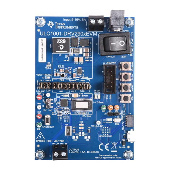
Figure 3-1. ULC1001-DRV290xEVM Top View...........................................................................................................................
Figure 3-2. EVM System Setup Example....................................................................................................................................
Figure 3-3. GUI Start-up..............................................................................................................................................................
Figure 4-1. System Configuration Matrix.....................................................................................................................................
Figure 4-2. LCS Impedance vs Temperature.............................................................................................................................
Figure 4-3. Water Cleaning LCS Voltage & Current .................................................................................................................
Figure 4-6. Auto Cleaning LCS Voltage & Current ...................................................................................................................
Layout..............................................................................................................................................16
Pane.......................................................................................................................................................16
Figure 5-3. GUI South Pane......................................................................................................................................................
Figure 5-4. Burst Parameters....................................................................................................................................................
Figure 5-5. Active Burst Example..............................................................................................................................................
Figure 5-6. Passive Burst Example...........................................................................................................................................
SLAU880C - DECEMBER 2022 - REVISED MAY 2024
Submit Document Feedback
ABSTRACT
Table of Contents
List of Figures
..................................................................................................................13
....................................................................................................................14
Copyright © 2024 Texas Instruments Incorporated
Table of Contents
ULC1001-DRV290x Evaluation Module
2
5
6
7
9
11
15
27
29
29
41
44
46
51
6
6
7
7
11
13
14
17
18
19
20
1
Advertisement
Table of Contents

Related Manuals for Texas Instruments ULC1001-DRV290 Series


Summary of Contents for Texas Instruments ULC1001-DRV290 Series
-
Page 1: Table Of Contents
ULC1001-DRV290x Evaluation Module ABSTRACT Texas Instruments created the Ultrasonic Lens Cleaning (ULC) system for removing water, ice, or other contaminants from automotive, security, and industrial lens systems. Ultrasonic Lens Cleaning improves visibility by efficiently clearing water, ice, and some contaminants. For some use cases, Ultrasonic Lens Cleaning eliminates the need for washer tubes, spray nozzles, or wipers. -
Page 2: General Texas Instruments High Voltage Evaluation (Ti Hv Evm) User Safety Guidelines
OMICRON electronics. All trademarks are the property of their respective owners. 1 General Texas Instruments High Voltage Evaluation (TI HV EVM) User Safety Guidelines Always follow TI's setup and application instructions, including use of all interface components within the recommended electrical rated voltage and power limits. -
Page 3: Introduction
Any other use or application are strictly prohibited by Texas Instruments. If the user is not qualified, then immediately halt further use of the HV EVM. 1. 1. Work Area Safety a. Keep work area clean and orderly. -
Page 4: Getting Started
Ultrasonic Lens Cleaning. Mechanical systems developed by other companies can also be driven with the ULC1001-DRV290x EVM. Texas Instruments’ LCS is designed using specific parameters and components to provide high reliability and excellent cleaning performance. For more mechanical details on the LCS, please refer the Mechanical Design Guides. -
Page 5: Connection Procedure
8. Flip the Power Switch switch to the on position (on = I). 9. Download and install the ULC1001 GUI available on mySecureSoftware. CAUTION Do not leave EVM powered when unattended. SLAU880C – DECEMBER 2022 – REVISED MAY 2024 ULC1001-DRV290x Evaluation Module Submit Document Feedback Copyright © 2024 Texas Instruments Incorporated... -
Page 6: Gui Setup
GUI automatically attempts to connect with the ULC1001-DRV290x EVM via the USB2ANY interface. Upon successful connection, the green lit connected indicator appears in the bottom right corner of the status bar ULC1001-DRV290x Evaluation Module SLAU880C – DECEMBER 2022 – REVISED MAY 2024 Submit Document Feedback Copyright © 2024 Texas Instruments Incorporated... -
Page 7: System Overview
Burst Parameters Amp (puV) Freq_Start (Hz) Freq_Stop (Hz) Num_Freq Delta_Freq (Hz) Duration (ms) Delay (ms) Modualtion Figure 4-1. System Configuration Matrix SLAU880C – DECEMBER 2022 – REVISED MAY 2024 ULC1001-DRV290x Evaluation Module Submit Document Feedback Copyright © 2024 Texas Instruments Incorporated... -
Page 8: System Isr Period
The on-board boost converter, LM5155, creates the voltage, VBST, which is tied to PVDD through the J7 header. Adjusting the resistor feedback network, specifically R35, can change the VBST voltage and thus changing the ULC1001-DRV290x Evaluation Module SLAU880C – DECEMBER 2022 – REVISED MAY 2024 Submit Document Feedback Copyright © 2024 Texas Instruments Incorporated... -
Page 9: System Calibration
The suggested order is burst 0, 5, 1, 2, 3. Each burst is described in Table 4-2. The calibration sequence is shown in Figure 5-7. SLAU880C – DECEMBER 2022 – REVISED MAY 2024 ULC1001-DRV290x Evaluation Module Submit Document Feedback Copyright © 2024 Texas Instruments Incorporated... -
Page 10: Register
When the calibration sequence is run, the temperature slope constant, USER_Params_tempParams_constant_C_Q21, is set to an appropriate value. ULC1001-DRV290x Evaluation Module SLAU880C – DECEMBER 2022 – REVISED MAY 2024 Submit Document Feedback Copyright © 2024 Texas Instruments Incorporated... -
Page 11: System Cleaning
4.4 System Cleaning Texas Instruments created three main cleaning modes for removing ice, mud, and water from the lens of the LCS and an Auto mode that can be programmed to drive a cleaning sequence when mass, such as water, is detected on the lens. -
Page 12: Table 4-4. Valid Cleaning Bursts
Additionally, there are two custom bursts (6, 7) that are not affected by calibration. The settings for all cleaning modes are described in Section 5.2.3. ULC1001-DRV290x Evaluation Module SLAU880C – DECEMBER 2022 – REVISED MAY 2024 Submit Document Feedback Copyright © 2024 Texas Instruments Incorporated... -
Page 13: Figure 4-3. Water Cleaning Lcs Voltage & Current
Figure 4-3. Water Cleaning LCS Voltage & Current Load -100 -200 Time [sec] Load Time [sec] Figure 4-4. Deice Cleaning LCS Voltage & Current SLAU880C – DECEMBER 2022 – REVISED MAY 2024 ULC1001-DRV290x Evaluation Module Submit Document Feedback Copyright © 2024 Texas Instruments Incorporated... -
Page 14: Figure 4-5. Mud Cleaning Lcs Voltage & Current
Figure 4-5. Mud Cleaning LCS Voltage & Current Load -100 -200 Time [sec] Load Time [sec] Figure 4-6. Auto Cleaning LCS Voltage & Current ULC1001-DRV290x Evaluation Module SLAU880C – DECEMBER 2022 – REVISED MAY 2024 Submit Document Feedback Copyright © 2024 Texas Instruments Incorporated... -
Page 15: System Diagnostics
System Overview 4.5 System Diagnostics Texas Instruments created two diagnostic modes for limiting power and detecting faults in the lens cover system. These modes are System Fault and Power. The valid burst for diagnostic modes are listed in Table 4-5. -
Page 16: Figure 5-1. Gui Top Level Layout
7-bit target I2C address, and switching between pages. Figure 5-2. GUI North Pane ULC1001-DRV290x Evaluation Module SLAU880C – DECEMBER 2022 – REVISED MAY 2024 Submit Document Feedback Copyright © 2024 Texas Instruments Incorporated... -
Page 17: Figure 5-3. Gui South Pane
The GUI Center Pane holds sub-panes and GUI widgets for the selected Register Map Page, High Level Page, or I C Configuration Page. Each page is described in the next sections. SLAU880C – DECEMBER 2022 – REVISED MAY 2024 ULC1001-DRV290x Evaluation Module Submit Document Feedback Copyright © 2024 Texas Instruments Incorporated... -
Page 18: High Level Page
Passive Burst Parameters. Figure 5-6 shows a depiction of how passive bursts are run. Figure 5-4. Burst Parameters ULC1001-DRV290x Evaluation Module SLAU880C – DECEMBER 2022 – REVISED MAY 2024 Submit Document Feedback Copyright © 2024 Texas Instruments Incorporated... -
Page 19: Figure 5-5. Active Burst Example
Changes modulation method between Direct Drive and standard AD modulation. AD modulation Modulation uses a carrier frequency that is 10 times the programmed frequency. SLAU880C – DECEMBER 2022 – REVISED MAY 2024 ULC1001-DRV290x Evaluation Module Submit Document Feedback Copyright © 2024 Texas Instruments Incorporated... -
Page 20: Figure 5-6. Passive Burst Example
Changes modulation method between Direct Drive and standard AD modulation. AD modulation Modulation uses a carrier frequency that is 10 times the programmed frequency. ULC1001-DRV290x Evaluation Module SLAU880C – DECEMBER 2022 – REVISED MAY 2024 Submit Document Feedback Copyright © 2024 Texas Instruments Incorporated... -
Page 21: Figure 5-7. Calibration Mode Sequence
Operating the LCS above 65°C can reduce the operating lifetime and potentially damage the LCS and is dependent on the mechanical Lens Cover System. SLAU880C – DECEMBER 2022 – REVISED MAY 2024 ULC1001-DRV290x Evaluation Module Submit Document Feedback Copyright © 2024 Texas Instruments Incorporated... -
Page 22: Table 5-5. Cal Mode Settings
USER_Params_Update_Expel_24 for Region 2 Clean_Expel_24 (15) • USER_Params_Update_Heat_Region_1 for Region 1 Heat_Region_1 (16) • USER_Params_Update_Heat_Region_2 for Region 2 Heat_Region_2 (17) ULC1001-DRV290x Evaluation Module SLAU880C – DECEMBER 2022 – REVISED MAY 2024 Submit Document Feedback Copyright © 2024 Texas Instruments Incorporated... -
Page 23: Figure 5-9. Voltage And Current Sense Amplifiers
R5 = 6kΩ. R6 = 2kΩ Differential Voltage (pk-pk) 1.3MΩ 6.34kΩ 294kΩ 422kΩ 360kΩ 30kΩ 1MΩ 150kΩ 150kΩ 30kΩ 1MΩ 150kΩ SLAU880C – DECEMBER 2022 – REVISED MAY 2024 ULC1001-DRV290x Evaluation Module Submit Document Feedback Copyright © 2024 Texas Instruments Incorporated... -
Page 24: Figure 5-10. Cleaning Mode Settings
5.2.3 Cleaning Mode Settings Texas Instruments created four main cleaning modes for removing ice, mud, and water from the lens of the LCS. The GUI allows select settings to be adjusted for these cleaning modes and also gives the user freedom to create two custom cleaning modes. -
Page 25: Table 5-8. Temperature Parameters
5.2.3.2 Water Cleaning Texas Instruments proprietary Water Cleaning Mode is composed of 4 bursts, enumerated bursts (8, 9, 13, 14). The first two bursts (8 and 9) utilize cleaning for one frequency region while the second two bursts (13 and 14) clean at a second frequency region. -
Page 26: Figure 5-11. Power And Diagnostic Settings
GUI Overview www.ti.com 5.2.4 Power and Diagnostic Settings Texas Instruments created two additional modes to regulate the power delivered to the LCS, identify the faults of LCS, and check for an open load condition on the output. Refer to Section 4.5 for more details on the diagnostic modes. -
Page 27: Register Map Page
Register Map Page, these registers do not have the values optimized until the user switches back to the High Level Page. Figure 5-12. GUI Register Map Page (Hardware Register) SLAU880C – DECEMBER 2022 – REVISED MAY 2024 ULC1001-DRV290x Evaluation Module Submit Document Feedback Copyright © 2024 Texas Instruments Incorporated... -
Page 28: Figure 5-13. Gui Register Map Page (Software Registers)
USER_Params_fisr_Hz_Q9 has a Q9 notation. For example, 976.5625 in Q9 notation can be calculated using the formula 976.5625∗2^9 = 500000. Then convert 500000 to binary 32-bit value. ULC1001-DRV290x Evaluation Module SLAU880C – DECEMBER 2022 – REVISED MAY 2024 Submit Document Feedback Copyright © 2024 Texas Instruments Incorporated... -
Page 29: I 2 C Configuration Page
The status log is meant for recording Register Read/Write sequences. To create register read/write scripts, see Section 5.5.9. Figure 5-15. GUI Status Bar SLAU880C – DECEMBER 2022 – REVISED MAY 2024 ULC1001-DRV290x Evaluation Module Submit Document Feedback Copyright © 2024 Texas Instruments Incorporated... -
Page 30: Figure 5-16. Gui Status Log
PRAM, is 46 kb. For new designs, TI recommends to use a microcontroller that can hold the entire header file. In this case, the EEPROM chip is not necessary. ULC1001-DRV290x Evaluation Module SLAU880C – DECEMBER 2022 – REVISED MAY 2024 Submit Document Feedback Copyright © 2024 Texas Instruments Incorporated... - Page 31 SBWTDIO: J3-pin 3 goes to MSP-FET pin 1. • SBWTCK: J3-pin 4 goes to MSP-FET pin 7. • GND: J3-pin 5 goes to MSP-FET pin 9. SLAU880C – DECEMBER 2022 – REVISED MAY 2024 ULC1001-DRV290x Evaluation Module Submit Document Feedback Copyright © 2024 Texas Instruments Incorporated...
-
Page 32: Table 5-11. Reinit Mode Sequence
5-12. The sequences for reading faults is in Table 5-13, and the sequence for clearing faults is in Table 5-14. ULC1001-DRV290x Evaluation Module SLAU880C – DECEMBER 2022 – REVISED MAY 2024 Submit Document Feedback Copyright © 2024 Texas Instruments Incorporated... -
Page 33: Table 5-12. Faults And Flags
Change to page 0. Bit 2 = 1 clears sticky faults. Default register value is 0x01. Put device in software shutdown mode. SLAU880C – DECEMBER 2022 – REVISED MAY 2024 ULC1001-DRV290x Evaluation Module Submit Document Feedback Copyright © 2024 Texas Instruments Incorporated... - Page 34 R1 - Frequency and R2 - Frequency can be shifted from the values found using an impedance analyzer. ULC1001-DRV290x Evaluation Module SLAU880C – DECEMBER 2022 – REVISED MAY 2024 Submit Document Feedback Copyright © 2024 Texas Instruments Incorporated...
-
Page 35: Table 5-15. Calibration Mode Sequence
5.5.6 Run Cleaning Modes Texas Instruments created three main cleaning modes for removing ice, mud and water from the lens of the LCS and an Auto mode that can be programmed to drive a cleaning sequence when mass, such as water, is detected on the lens. -
Page 36: Table 5-16. Cleaning Mode Sequence
GUI.write_register("ULC1001","PWR_CTL",0x02) # returns device to Software Shutdown 5.5.7 Run Diagnostic Mode Texas Instruments created two additional modes to regulate the power delivered to the LCS, identify the faults of LCS, and check for an open load condition on the output. Refer to Section 4.5... -
Page 37: Table 5-18. Abort Sequence
Change to Page 0x1A 00000001 Abort the system Wait 1ms Change to Page 0 SW Reset Wait 2ms Re-load all registers SLAU880C – DECEMBER 2022 – REVISED MAY 2024 ULC1001-DRV290x Evaluation Module Submit Document Feedback Copyright © 2024 Texas Instruments Incorporated... - Page 38 GUI.write_register("USER_Commands","USER_Commands_userCommand",0x1) # set Abort Command time.sleep(x) # set appropriate wait time GUI.write_register("ULC1001","SW_RESET",0x1) time.sleep(x) # set appropriate wait time # Re-load all registers ULC1001-DRV290x Evaluation Module SLAU880C – DECEMBER 2022 – REVISED MAY 2024 Submit Document Feedback Copyright © 2024 Texas Instruments Incorporated...
-
Page 39: Figure 5-17. Script Menu
Some commands require a wait time for the system to initialize or be put into active mode. Inserting the Python Time library and using wait commands is possible. Figure 5-17. Script Menu Figure 5-18. Python Recording Window SLAU880C – DECEMBER 2022 – REVISED MAY 2024 ULC1001-DRV290x Evaluation Module Submit Document Feedback Copyright © 2024 Texas Instruments Incorporated... -
Page 40: Figure 5-19. Saving Recorded Python Script
GUI Overview www.ti.com Figure 5-19. Saving Recorded Python Script Figure 5-20. Running Recorded Python Script ULC1001-DRV290x Evaluation Module SLAU880C – DECEMBER 2022 – REVISED MAY 2024 Submit Document Feedback Copyright © 2024 Texas Instruments Incorporated... -
Page 41: Hardware Design Files
IRQZ 10.0k 10.0k MSP430_SDZ IRQZ 3.3V VSNS_P 294k 0.1% 1.3M 0.1% 6.34k 3.3V 0.1% 3.3V Figure 6-1. ULC1001-DRV290x EVM Schematic SLAU880C – DECEMBER 2022 – REVISED MAY 2024 ULC1001-DRV290x Evaluation Module Submit Document Feedback Copyright © 2024 Texas Instruments Incorporated... -
Page 42: Figure 6-2. Ulc1001-Drv290X Evm Msp430 Schematic
DVCC2 DVSS2 0.22µF 0.22µF MSP430F5510IRGZR 1000pF 3.3V-MSP SBWTDIO SBWTCK 0.1µF 0.1µF 0.1µF LPPB061NGCN-RC 10µF Figure 6-2. ULC1001-DRV290x EVM MSP430 Schematic ULC1001-DRV290x Evaluation Module SLAU880C – DECEMBER 2022 – REVISED MAY 2024 Submit Document Feedback Copyright © 2024 Texas Instruments Incorporated... -
Page 43: Figure 6-3. Ulc1001-Drv290X Evm Power Supplies
PBC03DAAN MODE low = FPWM 3.3VREG MODE high = PFM PGND PGND 10.0k PGND Figure 6-3. ULC1001-DRV290x EVM Power Supplies SLAU880C – DECEMBER 2022 – REVISED MAY 2024 ULC1001-DRV290x Evaluation Module Submit Document Feedback Copyright © 2024 Texas Instruments Incorporated... -
Page 44: Pcb Layouts
The ULC1001-DRV290X EVM Layer Plots are shown in the figures below. Figure 6-4. Top Layer Figure 6-5. Signal Layer 1 Figure 6-6. Signal Layer 2 Figure 6-7. Bottom Layer ULC1001-DRV290x Evaluation Module SLAU880C – DECEMBER 2022 – REVISED MAY 2024 Submit Document Feedback Copyright © 2024 Texas Instruments Incorporated... -
Page 45: Figure 6-8. Board Dimensions
Hardware Design Files Figure 6-8. Board Dimensions SLAU880C – DECEMBER 2022 – REVISED MAY 2024 ULC1001-DRV290x Evaluation Module Submit Document Feedback Copyright © 2024 Texas Instruments Incorporated... -
Page 46: Bill Of Materials (Bom)
CAP, CERM, 2.2uF, 50V, +/- 10%, X7R, AEC-Q200 0805 CGA4J3X7R1H225K125AB 2.2uF Grade 1, 0805 CAP, CERM, 0.1µF, 50V,+/- 10%, X7R, AEC-Q200 0402 CGA2B3X7R1H104K050BD 0.1uF Grade 1, 0402 ULC1001-DRV290x Evaluation Module SLAU880C – DECEMBER 2022 – REVISED MAY 2024 Submit Document Feedback Copyright © 2024 Texas Instruments Incorporated... - Page 47 SMT2_7MM3_6MM6 SRP7050TA-220M Bourns 22uH 2.5A 170mOhm Max Nonstandard Inductor, Shielded, Composite, 6.8uH, 18.5A, Inductor, 11.3x10x10mm XAL1010-682MEB Coilcraft 6.8uH 0.01ohm, SMD SLAU880C – DECEMBER 2022 – REVISED MAY 2024 ULC1001-DRV290x Evaluation Module Submit Document Feedback Copyright © 2024 Texas Instruments Incorporated...
- Page 48 0603 CRCW0603499RFKEAC Vishay-Dale R40, R41, R43, R44 RES, 10 k, 5%, 0.063 W, AEC-Q200 Grade 0, 0402 0402 CRCW040210K0JNED Vishay-Dale ULC1001-DRV290x Evaluation Module SLAU880C – DECEMBER 2022 – REVISED MAY 2024 Submit Document Feedback Copyright © 2024 Texas Instruments Incorporated...
- Page 49 DRY0006A TPD4E004DRYR Texas Instruments Data Interfaces, DRY0006A (USON-6) 10MHz XO (Standard) CMOS Oscillator 3.3V SMT_XTAL_2MM0_1MM LFSPXO071190REEL Enable/Disable 4-SMD, No Lead SLAU880C – DECEMBER 2022 – REVISED MAY 2024 ULC1001-DRV290x Evaluation Module Submit Document Feedback Copyright © 2024 Texas Instruments Incorporated...
- Page 50 Table 6-1. ULC1001-DRV290X EVM Bill of Materials (continued) Designator Quantity Description Package Reference Part Number Manufacturer Value Crystal, 24.000MHz, 18pF, SMD 3.2x0.8x2.5mm ABM8-24.000MHZ-B2-T Abracon Corporation ULC1001-DRV290x Evaluation Module SLAU880C – DECEMBER 2022 – REVISED MAY 2024 Submit Document Feedback Copyright © 2024 Texas Instruments Incorporated...
-
Page 51: Revision History
Changes from Revision * (September 2022) to Revision A (February 2023) Page • Updated Equation 3 Equation 5.........................23 • Added comments for Q-point notation......................27 SLAU880C – DECEMBER 2022 – REVISED MAY 2024 ULC1001-DRV290x Evaluation Module Submit Document Feedback Copyright © 2024 Texas Instruments Incorporated... - Page 52 TI products. TI’s provision of these resources does not expand or otherwise alter TI’s applicable warranties or warranty disclaimers for TI products. TI objects to and rejects any additional or different terms you may have proposed. IMPORTANT NOTICE Mailing Address: Texas Instruments, Post Office Box 655303, Dallas, Texas 75265 Copyright © 2024, Texas Instruments Incorporated...
Need help?
Do you have a question about the ULC1001-DRV290 Series and is the answer not in the manual?
Questions and answers