Sign In
Upload
Manuals
Brands
Texas Instruments Manuals
Motherboard
ULC1001
Texas Instruments ULC1001 Manuals
Manuals and User Guides for Texas Instruments ULC1001. We have
1
Texas Instruments ULC1001 manual available for free PDF download: User Manual
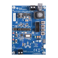
Texas Instruments ULC1001 User Manual (52 pages)
Evaluation Module
Brand:
Texas Instruments
| Category:
Motherboard
| Size: 2.58 MB
Table of Contents
Table of Contents
1
General Texas Instruments High Voltage Evaluation (TI HV EVM) User Safety Guidelines
2
Introduction
3
Getting Started
4
Evaluation Kit Contents
4
Table 3-1. ULC1001-Drv290X EVM Port and Switch
4
Connection Procedure
5
GUI Setup
6
Figure 3-1. ULC1001-Drv290Xevm Top View
6
Figure 3-2. EVM System Setup Example
6
System Overview
7
Figure 3-3. GUI Start-Up
7
Figure 4-1. System Configuration Matrix
7
System ISR Period
8
System Drive Voltage
8
Table 4-1. ISR Configuration Settings
8
System Calibration
9
Register
10
Table 4-2. Valid Calibration Bursts
10
Table 4-3. DC Bias Calibration Settings
10
System Cleaning
11
Figure 4-2. LCS Impedance Vs Temperature
11
Table 4-4. Valid Cleaning Bursts
12
Figure 4-3. Water Cleaning LCS Voltage & Current
13
Figure 4-4. Deice Cleaning LCS Voltage & Current
13
Figure 4-5. Mud Cleaning LCS Voltage & Current
14
Figure 4-6. Auto Cleaning LCS Voltage & Current
14
System Diagnostics
15
GUI Overview
15
GUI Top Level Layout
15
Table 4-5. Valid Diagnostic Bursts
15
Figure 5-1. GUI Top Level Layout
16
Figure 5-2. GUI North Pane
16
Figure 5-3. GUI South Pane
17
Table 5-1. Menu Bar Functions
17
High Level Page
18
Figure 5-4. Burst Parameters
18
Figure 5-5. Active Burst Example
19
Table 5-2. Active Burst Parameters
19
Figure 5-6. Passive Burst Example
20
Table 5-3. Passive Burst Parameters
20
Figure 5-7. Calibration Mode Sequence
21
Figure 5-8. Calibration Settings and Parameters
21
Table 5-4. Temperature Calibration Setting
21
Table 5-5. Cal Mode Settings
22
Figure 5-9. Voltage and Current Sense Amplifiers
23
Table 5-6. Voltage and Current Sense Resistor Reference Values
23
Figure 5-10. Cleaning Mode Settings
24
Table 5-7. Mass Detect Parameters
24
Table 5-8. Temperature Parameters
25
Figure 5-11. Power and Diagnostic Settings
26
Table 5-9. Power Parameters
26
Table 5-10. Diagnostic Parameters
26
Register Map Page
27
Figure 5-12. GUI Register Map Page
27
Figure 5-13. GUI Register Map Page (Software Registers)
28
I 2 C Configuration Page
29
GUI Functions
29
Figure 5-14. I 2 C Configuration
29
Figure 5-15. GUI Status Bar
29
Figure 5-16. GUI Status Log
30
Table 5-11. Reinit Mode Sequence
32
Table 5-12. Faults and Flags
33
Table 5-13. Read Flags and Faults Sequence
33
Table 5-14. Clear Flags and Faults Sequence
33
Table 5-15. Calibration Mode Sequence
35
Table 5-16. Cleaning Mode Sequence
36
Table 5-17. Diagnostic Mode Sequence
36
Table 5-18. Abort Sequence
37
Figure 5-17. Script Menu
39
Figure 5-18. Python Recording Window
39
Figure 5-19. Saving Recorded Python Script
40
Figure 5-20. Running Recorded Python Script
40
Hardware Design Files
41
Schematics
41
Figure 6-1. ULC1001-Drv290X EVM Schematic
41
Figure 6-2. ULC1001-Drv290X EVM MSP430 Schematic
42
Figure 6-3. ULC1001-Drv290X EVM Power Supplies
43
PCB Layouts
44
Figure 6-4. Top Layer
44
Figure 6-5. Signal Layer 1
44
Figure 6-6. Signal Layer 2
44
Figure 6-7. Bottom Layer
44
Figure 6-8. Board Dimensions
45
Bill of Materials (BOM)
46
Table 6-1. ULC1001-DRV290X EVM Bill of Materials
46
Revision History
51
Advertisement
Advertisement
Related Products
Texas Instruments ULC1001-DRV2911
Texas Instruments ULC1001-DRV2911EVM
Texas Instruments ULC1001-DRV290 Series
Texas Instruments ULN2003ADYYEVM
Texas Instruments UCD9080EVM
Texas Instruments UCC5870QDWJEVM-026
Texas Instruments UCC23513EVM-014
Texas Instruments UCD3138CC64EVM-030
Texas Instruments UCD90124EVM
Texas Instruments UCC21710
Texas Instruments Categories
Motherboard
Control Unit
Microcontrollers
Computer Hardware
Calculator
More Texas Instruments Manuals
Login
Sign In
OR
Sign in with Facebook
Sign in with Google
Upload manual
Upload from disk
Upload from URL