Table of Contents
Advertisement
Quick Links
www.ti.com
EVM User's Guide: ULC1001-DRV2911EVM
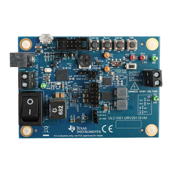
ULC1001-DRV2911 Evaluation Module
Description
Texas Instruments created the Ultrasonic Lens
Cleaning (ULC) system for removing water, ice, and
other contaminants from automotive, security, and
industrial lens systems. ULC improves visibility by
efficiently clearing water, ice, and some contaminants.
For some use cases, ULC eliminates the need
for washer tubes, spray nozzles, or wipers.
The ULC system is an electromechanical system
composed of a piezo based lens cover or lens
system, housing, and ULC1001-DRV2911 EVM. The
ULC1001-DRV2911 EVM is the electrical system
developed to excite the lens cover and expel
contaminants.
Get Started
•
ULC1001 product page
•
ULC EVM quick start video
•
USB2ANY tool page
SLAU915 – MAY 2024
Submit Document Feedback
Features
•
Integrate programmable cleaning modes
– Water (expelling)
– Deice (melting and expelling)
– Mud (dehydrating and expelling)
– Auto-cleaning (detecting mass and expelling)
– Custom cleaning modes
•
Embedded algorithms
– Lens system calibration
– Automatic mass detection
– Power regulation
– System diagnostics
•
System diagnostics
– DRV2911 fault reporting
– Lens system fault
– Transducer temperature regulation
2
•
I
C user interface
ULC1001-DRV2911EVM
Copyright © 2024 Texas Instruments Incorporated
Description
ULC1001-DRV2911 Evaluation Module
1
Advertisement
Table of Contents

Related Manuals for Texas Instruments ULC1001-DRV2911


Summary of Contents for Texas Instruments ULC1001-DRV2911
-
Page 1: Description
The ULC system is an electromechanical system – Lens system calibration composed of a piezo based lens cover or lens – Automatic mass detection system, housing, and ULC1001-DRV2911 EVM. The – Power regulation ULC1001-DRV2911 EVM is the electrical system – System diagnostics developed to excite the lens cover and expel contaminants. -
Page 2: Table Of Contents
Started....................................1 Features......................................1 1 Evaluation Module Overview..............................1.1 Introduction..................................1.2 Kit Contents..................................3 Specification..................................4 1.4 Device Information................................1.5 General Texas Instruments High Voltage Evaluation (TI HV EVM) User Safety Guidelines..........5 2 Hardware....................................2.1 Hardware Information.................................6 2.2 Connection Procedure............................... Software....................................8 3.1 GUI Setup.................................. -
Page 3: Evaluation Module Overview
Lens Cover System (LCS). For the purpose of this document, LCS refers to a lens cover system as well as an integrated piezo-based lens cleaning system. The ULC1001-DRV2911 EVM is the electrical system developed to drive the piezo element of the LCS causing expulsion of contaminants from the lens through mechanical vibrations. -
Page 4: Specification
ULC1001. The EVM also includes a MSP430 micro-controller which can control ULC1001 via four programmable push buttons. Various power devices are also implemented to supply the system. ULC1001-DRV2911 Evaluation Module SLAU915 – MAY 2024 Submit Document Feedback Copyright © 2024 Texas Instruments Incorporated... -
Page 5: General Texas Instruments High Voltage Evaluation (Ti Hv Evm) User Safety Guidelines
Any other use or application are strictly prohibited by Texas Instruments. If the user is not qualified, then immediately halt further use of the HV EVM. 1. 1. Work Area Safety a. Keep work area clean and orderly. -
Page 6: Hardware
2 Hardware 2.1 Hardware Information The ULC1001-DRV2911 EVM can be set up to drive multiple types of Lens Cover Systems. The EVM contains a flexible boost converter design and multiple filter configurations in the output path. Use the following instructions for assembling the hardware and installing the software components of the system. -
Page 7: Connection Procedure
Vp, 3.5A, 10-400 kHz. 4. Connect the 10-pin I C ribbon cable from the ULC1001-DRV2911 EVM to the USB2ANY using J1. 5. Connect the mini USB cable from the USB2ANY into the computer. 6. Verify all safety procedures are followed before powering on the device (for example, personal protective equipment or a protective enclosure for the EVM setup). -
Page 8: Software
30 bursts that can be configured for a wide range of frequencies. Bursts are enumerated from 0-23 and each burst has eight configurable parameters. The GUI is very useful for setting up the system and exporting configuration files for system integration. When a mode is enabled, the ULC1001-DRV2911 EVM drives each burst in the order shown in Figure 3-2 for a given mode. - Page 9 . The software register is used to configure the algorithm settings for processing current and voltage sense data. The relationship is ISR period = 512/Fs, where 512 is the USER_Params_blockSize. SLAU915 – MAY 2024 ULC1001-DRV2911 Evaluation Module Submit Document Feedback Copyright © 2024 Texas Instruments Incorporated...
- Page 10 LCS, such as change in wire length or wire gauge connecting the ULC1001-DRV2911 EVM to the LCS. When the ULC1001 is connected and powered, Calibration Mode must be configured and run first. There are 5 bursts that calibrate different algorithms.
- Page 11 When the calibration sequence is run, the temperature slope constant, USER_Params_tempParams_constant_C_Q21, is set to an appropriate value. Temperature (C) Figure 3-3. LCS Impedance vs Temperature SLAU915 – MAY 2024 ULC1001-DRV2911 Evaluation Module Submit Document Feedback Copyright © 2024 Texas Instruments Incorporated...
- Page 12 3.2.4 System Cleaning Texas Instruments created three main cleaning modes for removing ice, mud, and water from the lens of the LCS and an Auto mode that can be programmed to drive a cleaning sequence when mass, such as water, is detected on the lens.
- Page 13 Figure 3-5. Deice Cleaning LCS Voltage & Current Load -100 -200 Time [sec] Load Time [sec] Figure 3-6. Mud Cleaning LCS Voltage & Current SLAU915 – MAY 2024 ULC1001-DRV2911 Evaluation Module Submit Document Feedback Copyright © 2024 Texas Instruments Incorporated...
-
Page 14: Gui Overview
Figure 3-7. Auto Cleaning LCS Voltage & Current 3.2.5 System Diagnostics Texas Instruments created two diagnostic modes for limiting power and detecting faults in the lens cover system. These modes are System Fault and Power. The valid burst for diagnostic modes are listed in Table 3-5. - Page 15 The major functions include: configuring and monitoring communications, loading and saving configuration files, recording ULC1001-DRV2911 EVM register reads and writes, monitoring system faults, aborting and re-initializing the system, changing the 7-bit target I2C address, and switching between pages.
- Page 16 Address, or an incomplete GUI initialization. The Read/Write Indicator on the bottom left cycles quickly through register names when the GUI is reading or writing registers from the ULC1001-DRV2911 EVM. If no reading or writing is in progress, then the status can be idle. Double-clicking on the Read/Write indicator opens the Status Log window, which can be used to monitor I2C transactions.
- Page 17 (returned to automatically) Delay Sub-burst [1] Sub-burst [2] Sub-burst [3] Sub-burst [0] Active Burst Example (Num_Freq = 4) Time Figure 3-12. Active Burst Example SLAU915 – MAY 2024 ULC1001-DRV2911 Evaluation Module Submit Document Feedback Copyright © 2024 Texas Instruments Incorporated...
- Page 18 For Passive bursts, Num_Freq = 0. Duration for each excitation frequency drives the LCS. Duration [ms] GUI default is 98 ISR periods, 100ms for ULC1001-DRV2911 EVM. Delay [ms] The additional delay placed at the end of the burst. Changes modulation method between Direct Drive and standard AD modulation. AD modulation uses a Modulation carrier frequency that is 10 times the programmed frequency.
- Page 19 Table 3-9. Temperature Calibration Setting Parameter Description Temperature Slope [°C / Ω] LCS temperature estimation algorithm slope; provided by TI for provided LCS in ULC1001-DRV2911 EVM kit contents. CAUTION Operating the LCS above 65°C can reduce the operating lifetime and potentially damage the LCS and is dependent on the mechanical Lens Cover System.
- Page 20 USER_Params_Update_Expel_23 for Region 2 Clean_Expel_23 (14) • USER_Params_Update_Expel_24 for Region 2 Clean_Expel_24 (15) • USER_Params_Update_Heat_Region_1 for Region 1 Heat_Region_1 (16) • USER_Params_Update_Heat_Region_2 for Region 2 Heat_Region_2 (17) ULC1001-DRV2911 Evaluation Module SLAU915 – MAY 2024 Submit Document Feedback Copyright © 2024 Texas Instruments Incorporated...
- Page 21 Table 3-11. Voltage and Current Sense Resistor Reference Values R5 = 6kΩ. R6 = 2kΩ Differential Voltage (pk-pk) 1.3MΩ 6.34kΩ 294kΩ 422kΩ 360kΩ 30kΩ 1MΩ 150kΩ 150kΩ 30kΩ 1MΩ 150kΩ SLAU915 – MAY 2024 ULC1001-DRV2911 Evaluation Module Submit Document Feedback Copyright © 2024 Texas Instruments Incorporated...
- Page 22 3.3.2.3 Cleaning Mode Settings Texas Instruments created four main cleaning modes for removing ice, mud, and water from the lens of the LCS. The GUI allows select settings to be adjusted for these cleaning modes and also gives the user freedom to create two custom cleaning modes.
- Page 23 3.3.2.3.2 Water Cleaning Texas Instruments proprietary Water Cleaning Mode is composed of 4 bursts, enumerated bursts (8, 9, 13, 14). The first two bursts (8 and 9) utilize cleaning for one frequency region while the second two bursts (13 and 14) clean at a second frequency region.
- Page 24 Software www.ti.com 3.3.2.4 Power and Diagnostic Settings Texas Instruments created two additional modes to regulate the power delivered to the LCS, identify the faults of LCS, and check for an open load condition on the output. Refer to Section 3.2.5 for more details on the diagnostic modes.
- Page 25 Register Map Page, these registers do not have the values optimized until the user switches back to the High Level Page. Figure 3-19. GUI Register Map Page (Hardware Register) SLAU915 – MAY 2024 ULC1001-DRV2911 Evaluation Module Submit Document Feedback Copyright © 2024 Texas Instruments Incorporated...
- Page 26 USER_Params_fisr_Hz_Q9 has a Q9 notation. For example, 976.5625 in Q9 notation can be calculated using the formula 976.5625∗2^9 = 500000. Then convert 500000 to binary 32-bit value. ULC1001-DRV2911 Evaluation Module SLAU915 – MAY 2024 Submit Document Feedback Copyright © 2024 Texas Instruments Incorporated...
- Page 27 GUI is reading or writing registers from the ULC1001-DRV2911 EVM. Double clicking the Read/Write Status Indicator on the status bar opens a floating window which displays the entire status log, shown in Figure 3-23.
- Page 28 PRAM, is 46 kb. For new designs, TI recommends to use a microcontroller that can hold the entire header file. In this case, the EEPROM chip is not necessary. ULC1001-DRV2911 Evaluation Module SLAU915 – MAY 2024 Submit Document Feedback Copyright © 2024 Texas Instruments Incorporated...
- Page 29 ULC1001, and updates all of the GUI settings based on the ULC1001 settings. SLAU915 – MAY 2024 ULC1001-DRV2911 Evaluation Module Submit Document Feedback Copyright © 2024 Texas Instruments Incorporated...
- Page 30 OverTemp Threshold. INT_LTCH7, bit 6 Sticky Fault set by DRV2911. DRV_ERR Fault DRV_ERR2 Fault INT_LTCH7, bit 7 Second Fault from driver. Not used with DRV2911. ULC1001-DRV2911 Evaluation Module SLAU915 – MAY 2024 Submit Document Feedback Copyright © 2024 Texas Instruments Incorporated...
- Page 31 GUI.write_register("USER_Commands","USER_Commands_flag_newCommand",0x1) # sets lock bit time.sleep(0.01) #delay 10ms GUI.write_register("ULC1001","INT & CLK CFG",0x1D) # clears hardware sticky flauts GUI.write_register("ULC1001","PWR_CTL",0x02) # returns device to Software Shutdown SLAU915 – MAY 2024 ULC1001-DRV2911 Evaluation Module Submit Document Feedback Copyright © 2024 Texas Instruments Incorporated...
- Page 32 3.3.5.5 Run Calibration When the ULC1001-DRV2911 EVM is connected and powered, the calibration mode must be run first and needs to be repeated when there is a change in the impedance of the LCS. A change includes changing the wire length or wire gauge connection from the ULC1001 to the LCS.
- Page 33 When running any cleaning mode, all but the GUI Abort Sequence button is grayed out. The Abort Sequence button ends the running mode and resets the ULC1001-DRV2911 EVM to the state of the device just before the cleaning mode was initiated.
- Page 34 GUI.write_register("ULC1001","PWR_CTL",0x02) # returns device to Software Shutdown 3.3.5.7 Run Diagnostic Mode Texas Instruments created two additional modes to regulate the power delivered to the LCS, identify the faults of LCS, and check for an open load condition on the output. Refer to Section 3.2.5...
- Page 35 Change to Book 0 Change to Page 0x1A 00000001 Abort the system Wait 1ms Change to Page 0 SW Reset Wait 2ms Re-load all registers SLAU915 – MAY 2024 ULC1001-DRV2911 Evaluation Module Submit Document Feedback Copyright © 2024 Texas Instruments Incorporated...
- Page 36 Some commands require a wait time for the system to initialize or be put into active mode. Inserting the Python Time library and using wait commands is possible. Figure 3-24. Script Menu Figure 3-25. Python Recording Window ULC1001-DRV2911 Evaluation Module SLAU915 – MAY 2024 Submit Document Feedback Copyright © 2024 Texas Instruments Incorporated...
- Page 37 Software Figure 3-26. Saving Recorded Python Script Figure 3-27. Running Recorded Python Script SLAU915 – MAY 2024 ULC1001-DRV2911 Evaluation Module Submit Document Feedback Copyright © 2024 Texas Instruments Incorporated...
-
Page 38: Hardware Design Files
Hardware Design Files www.ti.com 4 Hardware Design Files 4.1 Schematics The ULC1001-DRV2911 EVM Schematics are shown in Figure 4-1, Figure 4-2, and Figure 4-3. I2C & USB2ANY CONNECTION 3.3V-DRV 3.3V-MSP 3.3V-ULC XG4C-1031 3.3V-ULC PVDD 5.10k FAULTZ AVDD FAULT AVDD 2.2k 2.2k... - Page 39 PGND 2.2MHz PGOOD3.3 PGND PEC03SAAN MODE low = FPWM 3.3V-MSP PGND MODE high = PFM PGND 10.0k PGND Figure 4-3. ULC1001-DRV2911 EVM Power Supplies SLAU915 – MAY 2024 ULC1001-DRV2911 Evaluation Module Submit Document Feedback Copyright © 2024 Texas Instruments Incorporated...
-
Page 40: Pcb Layouts
Hardware Design Files www.ti.com 4.2 PCB Layouts The ULC1001-DRV2911 EVM Layer Plots are shown in the figures below. Figure 4-4. Top Layer Figure 4-5. Signal Layer 1 Figure 4-6. Signal Layer 2 Figure 4-7. Bottom Layer Figure 4-8. Board Dimensions ULC1001-DRV2911 Evaluation Module SLAU915 –... -
Page 41: Bill Of Materials (Bom)
Hardware Design Files 4.3 Bill of Materials (BOM) Table 4-1. ULC1001-DRV2911 EVM Bill of Materials Designator Quantity Value Description Package Reference Part Number Manufacturer C1, C5, C16 CAP, CERM, 1uF, 16V, +/- 10%, X5R, 0402 0402 EMK105BJ105KVHF Taiyo Yuden... - Page 42 Hardware Design Files www.ti.com Table 4-1. ULC1001-DRV2911 EVM Bill of Materials (continued) Designator Quantity Value Description Package Reference Part Number Manufacturer C47, C49 0.22uF CAP, CERM, 0.22µF, 10V,+/- 10%, X7R, AEC-Q200 0402 LMK105B7224KVHF Taiyo Yuden Grade 1, 0402 0.47uF CAP, CERM, 0.47uF, 10V, +/- 10%, X7R, 0603...
- Page 43 Hardware Design Files Table 4-1. ULC1001-DRV2911 EVM Bill of Materials (continued) Designator Quantity Value Description Package Reference Part Number Manufacturer 1 Ohms ±1% 3W Chip Resistor 2010 (5025 Metric) 2010 VMP-1R00-1.0-U Isabellenhuette Automotive AEC-Q200, Current Sense, Moisture Resistant, Pulse Withstanding RES, 22, 5%, 1.5 W, AEC-Q200 Grade 0, 2512...
- Page 44 Hardware Design Files www.ti.com Table 4-1. ULC1001-DRV2911 EVM Bill of Materials (continued) Designator Quantity Value Description Package Reference Part Number Manufacturer 0 Ohms Jumper 0.125W, 1/8W Chip Resistor 0603 0603 ERJ-H3G0R00V Panasonic (1608 Metric) Automotive AEC-Q200 Thick Film R43, R55 RES, 47 k, 5%, 0.063 W, AEC-Q200 Grade 0, 0402...
- Page 45 Hardware Design Files Table 4-1. ULC1001-DRV2911 EVM Bill of Materials (continued) Designator Quantity Value Description Package Reference Part Number Manufacturer 512K I2C Serial EEPROM, DFN-8 DFN-8 24FC512-I/MF Microchip 4-Channel ESD Protection Array for High-Speed DRY0006A TPD4E004DRYR Texas Instruments Data Interfaces, DRY0006A (USON-6) 10MHz XO (Standard) CMOS Oscillator 3.3V...
-
Page 46: Additional Information
5 Additional Information 5.1 Trademarks Bode 100 ™ is a trademark of OMICRON electronics. All trademarks are the property of their respective owners. ULC1001-DRV2911 Evaluation Module SLAU915 – MAY 2024 Submit Document Feedback Copyright © 2024 Texas Instruments Incorporated... - Page 47 TI products. TI’s provision of these resources does not expand or otherwise alter TI’s applicable warranties or warranty disclaimers for TI products. TI objects to and rejects any additional or different terms you may have proposed. IMPORTANT NOTICE Mailing Address: Texas Instruments, Post Office Box 655303, Dallas, Texas 75265 Copyright © 2024, Texas Instruments Incorporated...
Need help?
Do you have a question about the ULC1001-DRV2911 and is the answer not in the manual?
Questions and answers