Table of Contents
Advertisement
MIXING CONSOLE
Owner's Manual
PHANTOM +48V
OFF
ON
INPUT
INPUT
INPUT
INPUT
INPUT
INPUT
MIC
MIC
MIC
MIC
MIC
MIC
LINE
LINE
LINE
LINE
LINE
LINE
INS
INS
INS
INS
I ⁄ O
I ⁄ O
I ⁄ O
I ⁄ O
INSERT I/O
OUT IN
1
2
3
4
5
GAIN
GAIN
GAIN
GAIN
GAIN
GAIN
+10
+10
+10
+10
+10
+10
-34
-34
-34
-34
-34
-16
-60
-16
-60
-16
-60
-16
-60
-16
-60
-16
PEAK
PEAK
PEAK
PEAK
PEAK
PEAK
HIGH
HIGH
HIGH
HIGH
HIGH
HIGH
-15
+15
-15
+15
-15
+15
-15
+15
-15
+15
-15
MID
MID
MID
MID
MID
MID
-15
+15
-15
+15
-15
+15
-15
+15
-15
+15
-15
LOW
LOW
LOW
LOW
LOW
LOW
-15
+15
-15
+15
-15
+15
-15
+15
-15
+15
-15
MONI 1
MONI 1
MONI 1
MONI 1
MONI 1
MONI 1
0
10
0
10
0
10
0
10
0
10
0
EFFECT
EFFECT
EFFECT
EFFECT
EFFECT
EFFECT
0
10
0
10
0
10
0
10
0
10
0
1
2
1
2
1
2
1
2
1
2
1
3
4
3
4
3
4
3
4
3
4
3
PAN
PAN
PAN
PAN
PAN
PAN
1
3
2
4
1
3
2
4
1
3
2
4
1
3
2
4
1
3
2
4
1
3
10
10
10
10
10
10
5
5
5
5
5
5
0
0
0
0
0
0
5
5
5
5
5
5
10
10
10
10
10
10
15
15
15
15
15
15
20
20
20
20
20
20
30
30
30
30
30
30
40
40
40
40
40
40
00
00
00
00
00
00
1
2
3
4
5
RTN
SEND
ST OUTPUT
L
(MONO)
INPUT
INPUT
MONI
1
MIC
MIC
R
EFFECT
MONI
2
L
1
9
11
L
L
(MONO)
(MONO)
3
LINE
LINE
2
10
R
12
R
4
GROUP
6
7
8
INPUT
INPUT
OUTPUT
GAIN
GAIN
GAIN
GAIN
+10
+10
-34
-34
-34
+10
-34
+10
-34
-60
-16
-60
-16
-60
L
R
PEAK
PEAK
PEAK
PEAK
TAPE IN
HIGH
HIGH
HIGH
HIGH
+15
-15
+15
-15
+15
-15
+15
-15
+15
MID
MID
MID
MID
TAPE IN
+15
-15
+15
-15
+15
-15
+15
-15
+15
ST
LOW
LOW
LOW
LOW
0
10
+15
-15
+15
-15
+15
-15
+15
-15
+15
MONI 1
MONI 1
MONI 1
MONI 1
DIGITAL
EFFECT
10
0
10
0
10
0
10
0
10
EFFECT
EFFECT
EFFECT
EFFECT
125
10
0
10
0
10
0
10
0
10
+12
2
1
2
1
2
1
2
1
2
6
0
4
3
4
3
4
3
4
3
4
6
-12
PAN
PAN
BAL
BAL
2
4
1
3
2
4
1
3
2
4
1
3
2
4
1
3
2
4
10
10
10
10
10
5
5
5
5
5
0
0
0
0
0
5
5
5
5
5
10
10
10
10
10
15
15
15
15
15
20
20
20
20
20
30
30
30
30
30
40
40
40
40
40
00
00
00
00
00
9 10
11 12
6
7
8
1
GROUP
R
C-R OUT
MIXING CONSOLE
PHONES
PHANTOM
POWER
0
10
L
R
C-R•PHONES
REC OUT
METER
RTN
SEND
C-R•PHONES
MONI
MONI
MONI 1
TAPE IN
0
10
0
10
0
10
ST
ST
EFFECT ⁄ MONI 2
EFFECT
ST
⁄ MONI
EFFECT
MONI 1
/ MONI 2
0
10
0
10
0
10
L
R
PEAK
+5
+3
VOCAL
L HALL
S HALL
ON
EFFECT
+1
MONI2
0
-1
250
500
1k
2k
4k
8k
-3
-5
+12
-7
6
-10
0
-15
6
-20
-12
ST GRAPHIC EQUALIZER
ST
GROUP
3 4
10
10
10
10
5
5
5
5
0
0
0
0
5
5
5
5
10
10
10
10
15
15
15
15
20
20
20
20
30
30
30
30
40
40
40
40
00
00
00
00
2
3
4
ST
GROUP
GROUP
GROUP
E
Advertisement
Table of Contents

Related Manuals for Yamaha MX12/4


Summary of Contents for Yamaha MX12/4
-
Page 1: Mixing Console
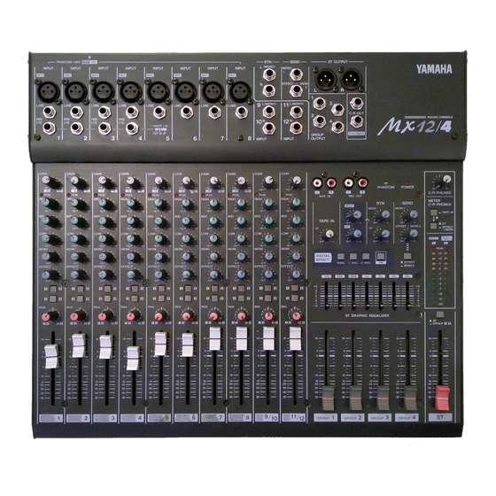
MIXING CONSOLE Owner's Manual PHANTOM +48V INPUT INPUT LINE LINE LINE I ⁄ O I ⁄ O I ⁄ O GAIN GAIN GAIN PEAK PEAK HIGH HIGH HIGH MONI 1 MONI 1 MONI 1 EFFECT EFFECT EFFECT SEND (MONO) INPUT INPUT INPUT INPUT... - Page 2 FCC requirements. Modifications not expressly approved by Yamaha may void your authority, granted by the FCC, to use the product. 2. IMPORTANT: When connecting this product to accessories and/or another product use only high quality shielded cables.
-
Page 3: Table Of Contents
Thank you for purchasing the Yamaha MX12/4 mixing console. The MX12/4 is a 12 in/4 group out mixer that provides an ideal balance of operability, functionality, and simplicity. In order to take full advantage of the MX12/4's functionality and to enjoy long and trouble-free use, please read this owner’s manual before use, and... -
Page 4: Front Panel
MONI MONI EFFECT EFFECT MX12/4—Owner’s Manual GAIN control Use this knob to adjust the sensitivity according to the input sig- nal level, so that the input level is appropriate. For the best balance of S/N ratio and dynamic range, adjust this knob so that the peak indicator 2 lights occasionally. -
Page 5: Channel Fader
The faders of unused channels should be lowered. PHANTOM PHANTOM MASTER INPUT LINE INPUT LINE L(MONO) INPUT GAIN 9/10 11/12 PEAK GAIN PEAK GAIN LOW MID HIGH PEAK Channel control section GROUP EFFECT MONI EFFECT MONI EFFECT MONI MX12/4—Owner’s Manual... -
Page 6: Master Control Section
PHANTOM indicator This indicator will light when the PHANTOM switch (rear panel 2 ) is on. POWER indicator This indicator will light when the MX12/4's power is on. MX12/4—Owner’s Manual ST OUT output select switch This switch selects the signal which is output via the ST fader from the ST OUTPUT jacks. -
Page 7: Digital Effect
PEAK will light red as a warn- ing. Master control section ), the signal from the TAPE IN ), the same signal as the ST OUT- ), the signal of the MX12/4—Owner’s Manual... -
Page 8: Connector Section
The INS I/O jacks provide bi-directional connections using TRS (tip, ring, sleeve) phone jacks. These connections require a special insertion cable such as shown in the following dia- gram. to the INS I/O jack MX12/4—Owner’s Manual INPUT INPUT INPUT INPUT... - Page 9 Note: An insertion cable can also be used when connecting this jack to a stereo monitor sys- tem. PHONES This is a stereo phone type output jack for connecting a set of headphones. The source monitored by the headphones is selected by the C-R•PHONES output select switch (master control section C). Connector section MX12/4—Owner’s Manual...
-
Page 10: Rear Panel
Note: Although it will not cause problems to connect balanced dynamic microphones or line level devices with this switch turned on, connecting unbalanced devices or devices for which the center of the transformer is ungrounded may cause hum or malfunction. MX12/4—Owner’s Manual Pin 1: ground Pin 2: hot (+) Pin 3: cold (–) -
Page 11: Application Example
Main speakers Monitors speakers Power amp Power amp Effects processor C-R OUT ST OUT INS I/O Headphone TAPE IN PHONES MIXING CONSOLE Cassette deck REC OUT or DAT SEND Effects processor GROUP OUTPUT INPUT Mic and line input MX12/4—Owner’s Manual... -
Page 12: Specifications
Power consumption General Dimensions (WxHxD) 436.2x83.1x401.2mm Weight 7.0kg MX12/4—Owner’s Manual ST master/GROUP fader at nominal level and all channel fader at minimum. ST master/GROUP fader at nominal level One channel fader, Master level control at nominal level and all channel MONITOR2 OUT) level controls at minimum. -
Page 13: Input Specifications
Connector type Max. before clipping +24dB (12.3V) XLR-3-32 type +20dB (7.75V) Phone jack +20dB (7.75V) Phone jack +20dB (7.75V) Phone jack +20dB (7.75V) ST phone jack +10dBV (3.16V) RCA pin jack 100mW ST phone jack +20dB (7.75V) Phone jack MX12/4—Owner’s Manual... -
Page 14: Dimensions
Specifications Dimensions W:436.2 Units:mm Specifications are subject to change without prior notice. MX12/4—Owner’s Manual... -
Page 15: Block And Level Diagram
7 BAND ST GEQ 7 BAND ST GEQ MONI 1 EFFECT MONI 2 EFFECT/ MONI 2 EFFECT /MONI C-R.PHONES TAPE IN EFFECT,MONITOR GROUP,EFFECT,MONITOR GROUP,ST MX12/4—Owner’s Manual GROUP OUTPUT REC OUT OUTPUT MONI 1 SEND EFFECT/ MONI 2 C-R OUT PHONES –10 –20 –30 –40... - Page 16 YAMAHA CORPORATION VV68420 R0 1 IP P.O.Box 1, Hamamatsu, Japan 96 09 700 NP Printed in Taiwan...
Need help?
Do you have a question about the MX12/4 and is the answer not in the manual?
Questions and answers