Table of Contents
Advertisement
Quick Links
Advertisement
Table of Contents

Related Manuals for NI cRIO-903 Series


Summary of Contents for NI cRIO-903 Series
- Page 1 cRIO-903x Getting Started 2024-01-31...
-
Page 2: Table Of Contents
Installing a Ferrite on the USB Host Port Cables........47 Configuring the System in Measurement & Automation Explorer (MAX)... . . 48 ni.com... - Page 3 cRIO-903x Getting Started Setting a System Password..........48 Installing Software on the cRIO-903x.
- Page 4 Block Diagrams............. . . 80 ni.com...
-
Page 5: Crio-903X Getting Started
Getting Started cRIO-903x Getting Started This document describes the features of the NI cRIO-903x, and how to install, mount, and operate the controller. © National Instruments... -
Page 6: Unpacking The Kit
Never touch the exposed pins of connectors. Note Do not install a device if it appears damaged in any way. 3. Unpack any other items and documentation from the kit. Store the device in the antistatic package when the device is not in use. ni.com... -
Page 7: Verifying The Kit Contents
cRIO-903x Getting Started Verifying the Kit Contents Verify that the following items are included in the cRIO-903x kit. Figure 1. cRIO-9030/9031/9033/9034/9035/9036/9038/9039 Kit Contents 1. cRIO Controller with Power Connector and SD Card Slot Cover 2. USB A-to-B Cable 3. Ferrite (x2) 4. -
Page 8: Crio-903X Features
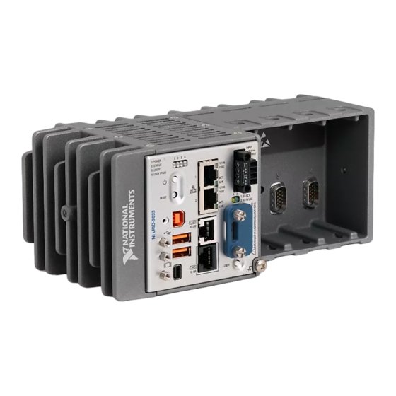
5. SD Card Removable Storage 6. Ground Screw 7. USER1 Button 8. RS-232 Serial Port 9. RS-485/422 (DTE) Serial Port 10. USB Host Ports 11. Mini DisplayPort 12. Cable Retention Mounts 13. USB Device Port 14. Power and Reset Buttons ni.com... -
Page 9: Ports And Connectors
cRIO-903x Getting Started Figure 4. cRIO-9032/9037 Front Panel 1. LEDs 2. Ethernet Ports 3. Power Connector 4. Antenna Port 2 5. Antenna Port 1 6. Ground Screw 7. WLAN LED 8. RS-232 Serial Port 9. RS-485/422 (DTE) Serial Port 10. USB Host Ports 11. - Page 10 1. RJ-45 Gigabit Ethernet Ports 2. Power Connector 3. SD Card Removable Storage 4. RS-232 Serial Port 5. RS-485/422 (DTE) Serial Port 6. Mini DisplayPort 7. USB Host Ports 8. USB Device Port Figure 6. cRIO-9032/9037 Ports and Connectors ni.com...
- Page 11 No Connect RX_D- Note Both Ethernet ports perform automatic crossover configuration so you do not need to use a crossover cable to connect to a host computer. The following NI Ethernet cables are available for the cRIO-903x. © National Instruments...
- Page 12 If you apply power to both the V1 and V2 inputs, the cRIO-903x operates from the V1 input. If the input voltage to V1 is insufficient, the cRIO-903x operates from the V2 input. The cRIO-903x has reverse-voltage protection. The following NI power supplies and accessories are available for the cRIO-903x. ni.com...
- Page 13 SD Card Removable Storage and SD Slot Cover (cRIO-9030/9031/9033/9034/9035/9036/9038/9039) The cRIO-903x provides an SD card slot that can read from and write to NI-approved SD cards. You must use the SD card slot cover to protect the SD card in hazardous locations.
- Page 14 RP-SMA (female) extension cables to route antennas outside of enclosure. Do not route C Series module cabling near either antenna. ■ Do not position the antennas in an orientation that crosses the antenna ■ keepout shown in the following figure. Figure 7. Antenna Keepout Antenna Keepout ni.com...
- Page 15 Use the Serial VIs to read from and write to the serial port. Refer to the LabVIEW Help for information about the Serial VIs. Find examples on how to use NI-Serial or NI-VISA to perform serial communication in the NI Example Finder. The NI Example Finder is located at Help » Find Examples. Note The RS-232 serial port cannot be accessed by the user application when the Console Out startup option is enabled.
- Page 16 (DTE) port, refer to the specifications for your controller. Find examples on how to use NI-Serial or NI-VISA to perform serial communication in the NI Example Finder. The NI Example Finder is located at Help » Find Examples. The following table shows the pinout for the RS-485/422 (DTE) serial port.
- Page 17 cRIO-903x Getting Started Table 10. RS-485/422 (DTE) Serial Port Pinout Pinout Signal No Connect TXD- TXD+ No Connect No Connect RXD- RXD+ No Connect No Connect Isolated GND Notice To ensure the specified EMC performance, you must use an isolated cable with the RS-485/422 (DTE) serial port. The following accessory meets this requirement.
- Page 18 électrique. The following table shows the pinout for the Mini DisplayPort. Table 12. Mini DisplayPort Pinout Signal Pinout Signal DP_PWR AUX_CH(n) ML_Lane2(n) AUX_CH(p) ML_Lane2(p) ML_Lane3(n) ML_Lane1(n) ML_Lane3(p) ML_Lane1(p) CONFIG2 ML_Lane0(n) CONFIG1 ML_Lane0(p) Hot Plug ni.com...
- Page 19 The following adapters are available to connect the Mini DisplayPort to full-size DisplayPort, VGA, or DVI. The cRIO-903x only supports DVI single link. Refer to the cRIO-903x pricing page on ni.com for a complete list of cables and accessories. Table 13. Mini DisplayPort Accessories...
- Page 20 Table 14. USB Host Port Pinout Pinout Signal Description Cable power (5 V) USB data- USB data+ Ground The following NI cable is available for the cRIO-903x. Table 15. USB Host Port Cable Cable Length Part Number USB Extension with Retention, 0.5 m 152166-0R5...
-
Page 21: Buttons
Pinout Signal Description USB data+ USB data- Ground Cable power (5 V) The following NI cable is available for the cRIO-903x. Table 16. USB Device Port Cable Cable Length Part Number USB Cable 157788-01 Buttons The cRIO-903x provides the following buttons. - Page 22 BIOS. If the cRIO-903x becomes unresponsive, you can power it off by holding the power button for 4 seconds. RESET Button Press the RESET button to reset the processor in the same manner as cycling power. ni.com...
-
Page 23: Leds
cRIO-903x Getting Started System Reset The following figure shows the reset behavior of the cRIO-903x. Figure 10. Reset Button Behavior Press and hold RESET button for < 5 s Press and hold RESET button for ≥ 5 s • Console Out enabled Safe Mode Run Mode •... - Page 24 Getting Started Figure 11. cRIO-9030/9031/9033/9034/9035/9036/9038/9039 LEDs 1. POWER LED 2. STATUS LED 3. USER1 LED 4. USER FPGA1 LED 5. Gigabit Ethernet LEDs 6. SD LEDs Figure 12. cRIO-9032/9037 LEDs 1. POWER LED 2. STATUS LED 3. USER1 LED ni.com...
- Page 25 cRIO-903x Getting Started 4. USER FPGA1 LED 5. Gigabit Ethernet LEDs 6. WLAN LED POWER LED Indicators The following table lists the POWER LED indicators. Table 17. POWER LED Indicators LED Color LED Pattern Indication Green Solid The cRIO-903x is powered from the V1 input.
- Page 26 The software has crashed twice without rebooting or cycling power between crashes. Continuously blinks The cRIO-903x has not booted into NI Linux Real-Time. The cRIO-903x either booted into an unsupported operating system, was interrupted during the boot process, or detected an unrecoverable software error.
- Page 27 RT LEDs VI, refer to the LabVIEW Help. USER FPGA1 Green/Yellow Use the LabVIEW FPGA Module and NI CompactRIO and Drivers software to define the USER FPGA1 LED. Use the USER FPGA1 LED to help debug your application or retrieve application status.
- Page 28 Solid The SD card in the slot is mounted in the operating system. Do not remove the SD card while this LED is lit. WLAN Status LED Indicators (cRIO-9032/9037) The following table describes the WLAN Status LED indicators. ni.com...
-
Page 29: Chassis Grounding Screw
Solder the other end of the wire to the cable shield. Use shorter wire for better EMC performance. For more information about ground connections, visit ni.com/info and enter the Info Code emcground. FPGA DRAM (cRIO-9034/9039) The cRIO-903x contains onboard dynamic random-access memory (DRAM) that is directly accessible from the LabVIEW FPGA VI. -
Page 30: Internal Real-Time Clock
Getting Started Find DRAM memory integrity and memory throughput examples for LabVIEW FPGA in the NI Example Finder. The NI Example Finder is located on the Help menu in the LabVIEW Help. Refer to the specifications for your controller for the DRAM density and the maximum theoretical bandwidth. - Page 31 UNIX-style file systems support the concept of a symbolic link, which allows access to a file using an alternative file path. For example, it is possible to link /C/ni-rt/ system, where dynamic libraries are deployed on other LabVIEW Real-Time targets, to /usr/local/lib, where they are stored on the cRIO-903x, if the application requires this.
-
Page 32: Installing Software On The Host Computer
Sequence Software LabVIEW LabVIEW Real-Time Module LabVIEW FPGA Module (see note) NI CompactRIO and Drivers Note LabVIEW FPGA Module is not required when using Scan Interface mode. To program the user-accessible FPGA on the cRIO-903x, LabVIEW FPGA Module is required. -
Page 33: Installing C Series Modules
cRIO-903x Getting Started Installing C Series Modules Complete the following steps to install a C Series module. Figure 13. Installing C Series Modules 1. Verify that power is not connected to the I/O connector(s) on the C Series module. If the system is in a nonhazardous location, the cRIO-903x can be powered on when you install modules. -
Page 34: Installing The Antennas
(cRIO-9032/9037) Complete the following steps to install the antennas on the cRIO-903x. Note NI recommends connecting both antennas for optimal wireless performance and reliability. 1. Screw an antenna to the primary wireless connector. Hand tighten the antenna to the connector. -
Page 35: Connecting The Crio-903X To Ground
Solder the other end of the wire to the cable shield. Use shorter wire for better EMC performance. For more information about ground connections, visit ni.com/info and enter the Info Code emcground. © National Instruments... -
Page 36: Connecting The Crio-903X To Power
(cRIO-9030/9031/9032/9033/9034) 9 V to 30 V, 40 W minimum ■ (cRIO-9035/9036/9037/9038/9039) 9 V to 30 V, 46 W minimum ■ NI recommends the power supplies listed in the following table for the cRIO-903x. Table 23. NI Power Supplies Power Supply Part Number... - Page 37 Getting Started Power Supply Part Number NI PS-10 Desktop Power Supply (24 V DC, 5 A, 782698-01 100 V AC to 120 V AC/200 V AC to 240 V AC input) What to Do Complete the following steps to connect a power supply to the cRIO-903x.
-
Page 38: Powering On The Crio-903X
When you power on the cRIO-903x for the first time, the device boots into safe mode. The POWER LED illuminates, the STATUS LED illuminates briefly, and then the STATUS LED blinks twice every few seconds. Related reference: STATUS LED Indicators ■ ni.com... -
Page 39: Connecting The Crio-903X To The Host Computer Or Network
1. Power on the host computer. 2. Connect the cRIO-903x to the host computer using the USB A-to-B cable. Notice NI requires the use of a locking USB cable (157788-01) to meet the shock and vibration specifications, as listed in the specifications for your controller. -
Page 40: Finding The Crio-903X On The Network (Dhcp)
Getting Started Complete the following steps to connect the cRIO-903x to a host computer or Ethernet network using the RJ-45 Gigabit Ethernet port 1. NI recommends using the RJ-45 Gigabit Ethernet port 1 for communication with deployed systems. Note You can configure the RJ-45 Gigabit Ethernet port 2 in Measurement &... -
Page 41: Finding The Crio-903X On The Network (Static Ip)
Getting Started MAX lists the system under the model number followed by the serial number, such as NI-cRIO-903x-1856AAA. Finding the cRIO-903x on the Network (Static IP) Complete the following steps to find the cRIO-903x on the network if the host computer is using a static IP address. -
Page 42: Connecting The Crio-903X To A Wireless Network
Getting Started MAX lists the system under the model number followed by the serial number, such as NI-cRIO-903x-1856AAA. c. Select the Network Settings tab near the bottom of the window. d. Select Static on the Configure IPv4 Address control. -
Page 43: Creating A Wireless Network With The Crio-903X
2. Expand Remote Systems in the configuration tree and locate your system. 3. Select your target. MAX lists the system under the model number followed by the serial number, such as NI-cRIO-903x-1856AAA. 4. Click the Network Settings tab. 5. Select your country. -
Page 44: What To Do When The Crio-903X Is Not Communicating With The Network
NI CompactRIO Device Drivers. If you have recently upgraded LabVIEW, you must reinstall NI CompactRIO Device Drivers. Ensure that the NI USBLAN adapter is recognized in the Device Manager. On ■ Windows 7, select Start » Control Panel » Device Manager » Network... -
Page 45: Verifying The System Ip Configuration
Getting Started adapters » National Instruments » USBLAN adapter. If the USBLAN adapter is not recognized, you must reinstall NI CompactRIO Device Drivers. Temporarily disable any network firewalls or other security software. ■ Verifying the System IP Configuration 1. Put the cRIO-903x in safe mode and enable the RS-232 serial port by holding the RESET button down for 5 seconds. -
Page 46: Troubleshooting Network Connectivity With The Reset Button
1. Hold the RESET button for 5 seconds, and then release it to boot the controller in safe mode and enable Console Out. 2. Hold the RESET button again for 5 seconds to boot the controller into safe mode, enable Console Out, and reset network adapters to default settings. ni.com... -
Page 47: Installing A Ferrite On The Usb Host Port Cables
cRIO-903x Getting Started Installing a Ferrite on the USB Host Port Cables You must install a ferrite around all USB cables connected to the USB host ports to ensure that the cRIO-903x meets all EMC standards applicable to your country. What to Use Ferrite (781233-02), included with the cRIO-903x ■... -
Page 48: Configuring The System In Measurement & Automation Explorer (Max)
1. Right-click your system and select Web Configuration. The NI Web-Based Configuration and Monitoring utility opens in your default browser and is where you set the password. If you have not installed Microsoft Silverlight, NI Web-based Configuration &... -
Page 49: Installing Software On The Crio-903X
7. Select NI Scan Engine from the software add-ons. Select any additional software to install. If you plan on using the cRIO-903x with the LabVIEW FPGA Module, you can click Next. Click NI Scan Engine if you plan on using the cRIO-903x without the LabVIEW FPGA Module. -
Page 50: Configuring Startup Options
You can use a serial-port terminal program to read the IP address and firmware version of the cRIO-903x. Use a null-modem cable to connect the RS-232 serial port to a computer. Make sure that the serial-port terminal program is configured to the following settings: ni.com... - Page 51 Rebooting the cRIO-903x with this setting on starts sshd on the cRIO-903x. Starting sshd enables logins over SSH, an encrypted communication protocol. Note Visit ni.com/info and enter the Info Code openssh for more information about SSH. LabVIEW Project Access Rebooting the cRIO-903x with this setting on enables you to add the target to a LabVIEW project.
-
Page 52: Installing The Module Immobilization Accessory
When using the Module Immobilization accessory, NI recommends installing the accessory prior to mounting the system in any enclosure because the accessory requires tool access to the top, right, and bottom of the cRIO-903x. -
Page 53: Module Immobilization Accessory Dimensions
Torx T10 driver. Tighten the screws to a maximum torque of 1.3 N · m (11.5 lb · in.). NI recommends using a liquid thread locker for all fasteners if the system is expected to experience vibration for an extended amount or time. - Page 54 Figure 17. cRIO-9030/9031/9032/9033/9034 Module Immobilization Accessory Dimensions 94.2 mm (3.71 in.) 1.6 mm 1.6 mm 220.4 mm (8.68 in.) (0.06 in.) (0.06 in.) Figure 18. cRIO-9035/9036/9037/9038/9039 Module Immobilization Accessory Dimensions 94.2 mm (3.71 in.) 1.6 mm 329.7 mm (12.98 in.) (0.06 in.) ni.com...
-
Page 55: Mounting The Controller
cRIO-903x Getting Started Mounting the Controller To obtain the maximum ambient temperature for your controller (55 °C for the cRIO-9030/9032/9034/9035/9037/9039, and 70 °C for the cRIO-9031/9033/9036/9038), you must mount the cRIO-903x in the reference mounting configuration shown in the following figure. Mounting the cRIO-903x in the reference mounting configuration ensures that your system will operate correctly across the full operating temperature range and provide optimal C Series module accuracy. -
Page 56: Mounting Requirements
Getting Started of 101.6 mm (4 in.) beyond all edges of the controller. Use the NI Panel Mounting Kit to ■ mount the cRIO-903x to a metallic surface that is at least 1.6 mm (0.062 in.) thick and extends a minimum of 101.6 mm (4 in.) beyond all edges of the controller. -
Page 57: Dimensions
(2.50 in.) 1. Measure the ambient temperature here. Dimensions The following figures show the front and side dimensions of the cRIO controller. For detailed dimensional drawings and 3D models, visit ni.com/dimensions and search for the module number. © National Instruments... - Page 58 Figure 23. cRIO-9030/9031/9032/9033/9034 Front Dimensions Figure 24. cRIO-9035/9036/9037/9038/9039 Front Dimensions 328.8 mm (12.95 in.) 107.0 mm (4.21 in.) 107.0 mm (4.21 in.) 88.1 mm (3.47 in.) 226.6 mm (8.92 in.) 8.6 mm (0.34 in.) Figure 25. cRIO-9032/9037 Antenna Dimensions ni.com...
-
Page 59: Mounting The Controller Directly On A Flat Surface
(2.10 in.) (2.10 in.) Mounting the Controller Directly on a Flat Surface For environments with high shock and vibration, NI recommends mounting the cRIO-903x directly on a flat, rigid surface using the mounting holes in the cRIO-903x. What to Use cRIO-903x ■... - Page 60 Getting Started Figure 27. cRIO-9030/9031/9032/9033/9034 Panel Mounting Figure 28. cRIO-9035/9036/9037/9038/9039 Panel Mounting 1. Prepare the surface for mounting the cRIO-903x using the surface mounting dimensions in Surface Mounting Dimensions. 2. Align the cRIO-903x on the surface. ni.com...
-
Page 61: Surface Mounting Dimensions
23.7 mm (0.94 in.) 9× ISO M4 × 0.7 Thread 8 mm Maximum Insertion Depth Mounting the Controller on a Panel You can use the NI panel mounting kit to mount the cRIO-903x on a panel. What to Use cRIO-903x ■... - Page 62 Getting Started M4 x 10 screws (x4) ■ (cRIO-9035/9036/9037/9038/9039) NI panel mounting kit, 157267-01: ■ Panel mounting plate ■ M4 x 10 screws (x6) ■ What to Do Complete the following steps to mount the cRIO-903x on a panel.
-
Page 63: Panel Mounting Dimensions
2. Fasten the panel mounting plate to the cRIO-903x using the screwdriver and M4 x 10 screws. NI provides these screws with the panel mounting kit. Tighten the screws to a maximum torque of 1.3 N · m (11.5 lb · in.). -
Page 64: Alternate Mounting Configurations
Contact NI for further details regarding the impact of common alternate mounting configurations on maximum operating temperature and module accuracy. Mounting the Controller on a DIN Rail You can use the NI DIN rail mounting kit to mount the cRIO-903x on a standard 35- mm DIN rail. What to Use cRIO-903x ■... - Page 65 Getting Started M4 x 10 screws (x2) ■ (cRIO-9035/9036/9037/9038/9039) NI DIN rail mounting kit, 157268-01: ■ DIN rail clip ■ M4 x 10 screws (x3) ■ What to Do Complete the following steps to mount the cRIO-903x on a DIN rail.
-
Page 66: Clipping The Device On A Din Rail
2. Fasten the DIN rail kit to the cRIO-903x using the screwdriver and M4 x 10 screws. NI provides these screws with the DIN rail mounting kit. Tighten the screws to a maximum torque of 1.3 N · m (11.5 lb · in.). -
Page 67: Mounting The Controller On A Desktop
You must use the NI DIN rail mounting kit (157254-01 for the cRIO-9030/9031/9032/9033/9034 or 157268-01 for the cRIO-9035/9036/9037/9038/9039), in addition to a rack-mounting kit. Mounting the Controller on a Desktop You can use the NI desktop mounting kit to mount the cRIO-903x on a desktop. What to Use cRIO-903x ■... -
Page 68: Desktop Mounting Dimensions
Figure 38. cRIO-9030/9031/9032/9033/9034 Desktop Mounting Front Dimensions Figure 39. cRIO-9035/9036/9037/9038/9039 Desktop Mounting Front Dimensions 361.7 mm (14.24 in.) 2× 17.2 mm (0.68 in.) 39.1 mm (1.54 in.) Figure 40. cRIO-903x Desktop Mounting Side Dimensions 127.2 mm (5.01 in.) 132.8 mm (5.23 in.) ni.com... -
Page 69: Bios Configuration
cRIO-903x Getting Started BIOS Configuration Resetting the System CMOS and BIOS Settings ■ Power-On Self Test Warning Messages ■ BIOS Setup Utility ■ Main Setup Menu ■ Advanced Setup Menu ■ Boot Setup Menu ■ Save & Exit Menu ■ Resetting the System CMOS and BIOS Settings The cRIO-903x BIOS configuration information is stored in a nonvolatile memory location that does not require a battery to preserve the settings. -
Page 70: Bios Setup Utility
5. Use the Down Arrow key to select Enter Setup and press <Enter>. The setup utility loads after a short delay. The Main setup menu is displayed when you first enter the BIOS setup utility. BIOS Setup Utility Keyboard Navigation Use the following keys to navigate through the BIOS setup utility: ni.com... -
Page 71: Main Setup Menu
cRIO-903x Getting Started Table 25. Navigation Keys Key(s) Function(s) Left Arrow, Right Arrow Move between the different setup menus. If you are in a submenu, these keys have no effect, and you must press <Esc> to leave the submenu first. Up Arrow, Down Arrow Move between the options within a setup menu. -
Page 72: Advanced Setup Menu
Turn On. The default value is Turn On. When set to Stay Off, the cRIO-903x returns to the soft off power state after AC power is restored. When set to Turn On, the cRIO-903x powers on when DC power is restored. ni.com... -
Page 73: Sata Configuration Submenu
cRIO-903x Getting Started Power Button Off Behavior—This setting specifies how the system responds ■ to the power button. Valid options are Normal and Disabled. The default value is Normal. If the value is Normal, the system responds to the power button as defined by the OS. -
Page 74: Boot Setup Menu
Boot Option Priorities—These settings specify the order in which the BIOS ■ checks for bootable devices, including the local hard disk drive, removable devices such as USB flash disk drives or USB CD-ROM drives, or the PXE network boot agent. The BIOS first attempts to boot from the device ni.com... -
Page 75: Boot Settings Configuration Submenu
cRIO-903x Getting Started associated with 1st Boot Device, followed by 2nd Boot Device and 3rd Boot Device. If multiple boot devices are not present, the BIOS setup utility does not display all of these configuration options. To select a boot device, press <Enter>... -
Page 76: Cd/Dvd Rom Drive Bbs Priorities Submenu
The Save & Exit setup menu includes the following settings: Save Changes and Reset—This setup utility then exits and reboots the ■ cRIO-903x. Any changes made to BIOS settings are stored in NVRAM. The <F10> key also selects this option. ni.com... - Page 77 cRIO-903x Getting Started Discard Changes and Reset—Any changes made to BIOS settings during this ■ session of the BIOS setup utility are discarded. The setup utility then exits and reboots the controller. The <Esc> key can also be used to select this option. Save Changes—Changes made to BIOS settings during this session are ■...
-
Page 78: Maintenance
Getting Started Maintenance If you need to clean the cRIO-903x, wipe it with a dry towel. ni.com... -
Page 79: Regional Regulatory Support For The Wireless Crio Controllers
Regional Regulatory Support for the Wireless cRIO Controllers (cRIO-9032/9037) Wireless regulatory compliance varies by region. NI offers regional support for three versions of the cRIO-9032/9037. Refer to the following table to determine which version of the cRIO-9032/9037 is supported for your region. -
Page 80: Block Diagrams
Ethernet Port 2 4 GB SATA Watchdog Disk-On-Chip RJ-50 USB 2.0 RS-232 Host Port Serial Port USB 2.0 RJ-50 Host Port RS-485/422 (DTE) Serial Port USB 2.0 SD Card Device Port Slot Xilinx Kintex-7 FPGA 7K70T Hardware Data cRIO-9030 ni.com... - Page 81 cRIO-903x Getting Started Figure 42. cRIO-9031 Block Diagram Intel Atom RJ-45 Gigabit Mini Ethernet Port 1 DisplayPort E3825 1.33 GHz Dual-Core System-On-Chip RJ-45 Gigabit 1 GB DDR3L Ethernet Port 2 4 GB SATA Watchdog Disk-On-Chip RJ-50 USB 2.0 RS-232 Host Port Serial Port USB 2.0 RJ-50...
- Page 82 8 GB SATA Watchdog Disk-On-Chip RJ-50 USB 2.0 RS-232 Host Port Serial Port USB 2.0 RJ-50 Host Port RS-485/422 (DTE) Serial Port USB 2.0 Device Port Antenna 2.4 / 5 GHz WLAN Radio Antenna Xilinx Kintex-7 FPGA 7K160T Hardware Data cRIO-9032 ni.com...
- Page 83 cRIO-903x Getting Started Figure 44. cRIO-9033 Block Diagram Intel Atom RJ-45 Gigabit Mini Ethernet Port 1 DisplayPort E3825 1.33 GHz Dual-Core System-On-Chip RJ-45 Gigabit 2 GB DDR3L Ethernet Port 2 8 GB SATA Watchdog Disk-On-Chip RJ-50 USB 2.0 RS-232 Host Port Serial Port USB 2.0 RJ-50...
- Page 84 16 GB SATA Watchdog Disk-On-Chip RJ-50 USB 2.0 RS-232 Host Port Serial Port USB 2.0 RJ-50 Host Port RS-485/422 (DTE) Serial Port USB 2.0 SD Card Device Port Slot Xilinx Kintex-7 FPGA 7K325T 128 MB DDR3 Hardware Data cRIO-9034 ni.com...
- Page 85 cRIO-903x Getting Started Figure 46. cRIO-9035 Block Diagram Intel Atom RJ-45 Gigabit Mini Ethernet Port 1 DisplayPort E3825 1.33 GHz Dual-Core System-On-Chip RJ-45 Gigabit 1 GB DDR3L Ethernet Port 2 4 GB SATA Watchdog Disk-On-Chip RJ-50 USB 2.0 RS-232 Host Port Serial Port USB 2.0 RJ-50...
- Page 86 Ethernet Port 2 4 GB SATA Watchdog Disk-On-Chip RJ-50 USB 2.0 RS-232 Host Port Serial Port USB 2.0 RJ-50 Host Port RS-485/422 (DTE) Serial Port USB 2.0 SD Card Device Port Slot Xilinx Kintex-7 FPGA 7K70T Hardware Data cRIO-9036 ni.com...
- Page 87 cRIO-903x Getting Started Figure 48. cRIO-9037 Block Diagram RJ-45 Gigabit Intel Atom Mini Ethernet Port 1 DisplayPort E3825 1.33 GHz Dual-Core System-On-Chip RJ-45 Gigabit 2 GB DDR3L Ethernet Port 2 8 GB SATA Watchdog Disk-On-Chip RJ-50 USB 2.0 RS-232 Host Port Serial Port USB 2.0 RJ-50...
- Page 88 Ethernet Port 2 8 GB SATA Watchdog Disk-On-Chip RJ-50 USB 2.0 RS-232 Host Port Serial Port USB 2.0 RJ-50 Host Port RS-485/422 (DTE) Serial Port USB 2.0 SD Card Device Port Slot Xilinx Kintex-7 FPGA 7K160T Hardware Data cRIO-9038 ni.com...
- Page 89 cRIO-903x Getting Started Figure 50. cRIO-9039 Block Diagram Intel Atom RJ-45 Gigabit Mini Ethernet Port 1 DisplayPort E3845 1.91 GHz Quad-Core System-On-Chip RJ-45 Gigabit 2 GB DDR3L Ethernet Port 2 16 GB SATA Watchdog Disk-On-Chip RJ-50 USB 2.0 RS-232 Host Port Serial Port USB 2.0 RJ-50...
Need help?
Do you have a question about the cRIO-903 Series and is the answer not in the manual?
Questions and answers