
Related Manuals for NI PCI-7390


Summary of Contents for NI PCI-7390
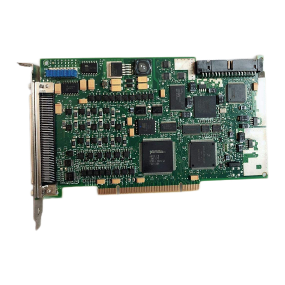
- Page 1 Motion Control NI PCI-7390 User Manual NI PCI-7390 User Manual November 2005 371520A-01...
- Page 2 Support Worldwide Technical Support and Product Information ni.com National Instruments Corporate Headquarters 11500 North Mopac Expressway Austin, Texas 78759-3504 USA Tel: 512 683 0100 Worldwide Offices Australia 1800 300 800, Austria 43 0 662 45 79 90 0, Belgium 32 0 2 757 00 20, Brazil 55 11 3262 3599,...
- Page 3 Warranty The NI PCI-7390 is warranted against defects in materials and workmanship for a period of one year from the date of shipment, as evidenced by receipts or other documentation. National Instruments will, at its option, repair or replace equipment that proves to be defective during the warranty period.
- Page 4 These classes are known as Class A (for use in industrial-commercial locations only) or Class B (for use in residential or commercial locations). All National Instruments (NI) products are FCC Class A products. Depending on where it is operated, this Class A product could be subject to restrictions in the FCC rules. (In Canada, the Department of Communications (DOC), of Industry Canada, regulates wireless interference in much the same way.) Digital...
-
Page 5: Table Of Contents
Contents About This Manual Conventions ........................vii Related Documentation....................viii Chapter 1 Introduction About the PCI-7390 Controller..................1-1 Features......................1-1 Hardware ......................1-2 RTSI ........................1-2 What You Need to Get Started ..................1-2 Software Programming Choices ..................1-3 National Instruments Application Software ..............1-3 Optional Equipment .......................1-4 Chapter 2 Configuration and Installation Software Installation ......................2-1... - Page 6 Breakpoint (Position Compare) Output Circuit........ 4-15 General-Purpose Inputs................... 4-15 General-Purpose Outputs ................4-16 General-Purpose Output Circuit ............4-16 Selecting Sinking or Sourcing General-Purpose Outputs....4-17 Connecting Inputs to the PCI-7390..............4-18 RTSI Connector......................4-21 RTSI Signal Considerations................4-21 Appendix A Specifications...
-
Page 7: About This Manual
About This Manual This manual describes the electrical and mechanical aspects of the National Instruments PCI-7390 and contains information about how to operate and program the device. The NI PCI-7390 is designed for PCI bus computers. Conventions The following conventions appear in this manual: <>... -
Page 8: Related Documentation
NI PCI-7390 Installation Guide—Refer to this document for installation instructions. • Getting Started with NI-Motion for NI 73xx Motion Controllers— Refer to this document for general information about the NI-Motion product. • Measurement & Automation Explorer Help for Motion—Refer to this document for configuration information. -
Page 9: Introduction
The PCI-7390 also performs arbitrary and complex motion trajectories through circular, spherical, or helical interpolation. Stepper axes can operate in open or closed-loop mode. The PCI-7390 uses quadrature encoders for position and velocity feedback (closed-loop only), and provides advanced encoder functions such as trigger (position capture) and breakpoint (position compare). -
Page 10: Hardware
PC for optimum command throughput and system performance. The PCI-7390 uses a 100-pin SCSI I/O connector. Each axis of the PCI-7390 has motion I/O for end-of-travel limit and home switch inputs, breakpoint (position compare) output, trigger (position capture) input,... -
Page 11: Software Programming Choices
Software Programming Choices NI-Motion is a simple but powerful high-level application programming interface (API) that makes programming the PCI-7390 easy. You can execute all setup and motion control functions by calling into a dynamically-linked library (DLL). You can use the full function set implementations for LabVIEW and LabWindows/CVI, or call the NI-Motion libraries from C and Visual Basic. -
Page 12: Optional Equipment
Connector blocks and shielded and unshielded 100-pin screw terminal wiring aids • Motion Connection Accessory (MCA) wiring connectivity blocks for easy and direct connections to Mitsubishi (NI part number 779612-01), Panasonic (NI part number 779613-01), and Yaskawa (NI part number 779611-01) drives. Refer to Appendix B, Motion Connection Accessories, for more information. -
Page 13: Configuration And Installation
NI-Motion Note If you do not install the NI-Motion driver software before attempting to use the PCI-7390, the system will not recognize the PCI-7390 and you will be unable to configure or use the device. Controller Configuration Because motion I/O-related configuration of the PCI-7390 is performed entirely with software, it is not necessary to set jumpers for motion I/O configuration. -
Page 14: Safety Information
Misuse of the device can result in a hazard. You can compromise the safety protection built into the device if the device is damaged in any way. If the device is damaged, return it to National Instruments (NI) for repair. Do not substitute parts or modify the device except as described in this document. - Page 15 Working voltage is the highest rms value of an AC or DC voltage that can occur across any particular insulation. MAINS is defined as a hazardous live electrical supply system that powers equipment. Suitably rated measuring circuits may be connected to the MAINS for measuring purposes. © National Instruments Corporation NI PCI-7390 User Manual...
-
Page 16: Hardware Installation
Chapter 2 Configuration and Installation Hardware Installation Install the PCI-7390 in any open PCI slot in the computer. Appendix A, Specifications, lists typical power requirements for the PCI-7390 controller. The following instructions are for general installation. Consult the computer user manual or technical reference manual for specific instructions and warnings. - Page 17 Chapter 2 Configuration and Installation Always power on the computer containing the PCI-7390, then the +24 V external Caution power supply, then initialize the controller before you power on the rest of the motion system. Power off in the reverse order.
-
Page 18: Hardware Overview
Hardware Overview This chapter presents an overview of the NI PCI-7390 functionality and capabilities. Figures 3-1 and 3-2 illustrate the functional components of the PCI-7390. 1 Jumpers for Selecting Output Type: Sinking or Sourcing 6 32-bit CPU 2 Non-Volatile Flash Memory... -
Page 19: User Connectors
2 Symbol Indicating CE Compliance 5 Assembly Number Label 3 Serial Number Label Figure 3-2. PCI-7390 Parts Locator Diagram (Back) User Connectors The 100-pin SCSI I/O connector provides all the signals for four axes of closed-loop motion control, including encoder feedback, limit and home inputs, breakpoint (position compare) outputs, trigger (position capture) input, inhibit (alarm) inputs, and in-position inputs. -
Page 20: Functional Overview
Dual Processor Architecture The PCI-7390 can perform up to four axes of simultaneous motion control in a preemptive, multitasking, real-time environment. An advanced dual-processor architecture that uses a real-time 32-bit CPU combined with a DSP and a custom FPGA give the PCI-7390 controllers high-performance capabilities. -
Page 21: Embedded Real-Time Operating System
ROM, which means that the controllers can electrically erase and reprogram their own ROM. Because all embedded firmware, including the RTOS, DSP code, and the FPGA configuration file of the PCI-7390 is stored in flash memory, you can upgrade the onboard firmware contents in the field for support and new-feature enhancement. -
Page 22: Axes And Motion Resources
A flash memory download utility is included with the NI-Motion software that ships with the controller. Axes and Motion Resources The PCI-7390 controller can control up to four axes of motion. The axes can be completely independent, simultaneously coordinated, or mapped in multidimensional groups called coordinate spaces. You also can simultaneously start coordinate spaces for multi-vector space coordinated motion control. -
Page 23: Motion Resources
PCI bus. The primary bidirectional data transfer port supports FIFO data passing in both send and readback directions. The PCI-7390 controller has both a command buffer for incoming commands and a return data buffer for returning data. -
Page 24: Signal Connections
Do not connect or disconnect the PCI-7390 controller I/O cable without first Caution disconnecting the +24 V power supply from all PCI-7390 boards. Failure to do so may result in damage to your system and/or PCI-7390 motion controller. I/O Connector... - Page 25 Axis 4 In-Position Axis 2 General-Purpose Input 0 Axis 4 General-Purpose Input 0 Axis 2 General-Purpose Input1*/Axis 4 Drive (Servo) Ready Axis 4 General-Purpose Input 1*/Axis 4 Drive (Servo) Ready Figure 4-1. 100-Pin I/O Connector Pin Assignments NI PCI-7390 User Manual ni.com...
- Page 26 Axis <1..4> Drive (Servo) Ready Optional general-purpose Emergency stop Isolated Ground Input Signal from an emergency input functionality stop switch that causes the controller to enter a reset Shutdown state © National Instruments Corporation NI PCI-7390 User Manual...
-
Page 27: Power Supply Connections
Power Supply Connections The PCI-7390 requires an external +24 V power supply for the optical isolation circuitry. An onboard regulator generates a +5 V output supply for both internal and external usage. Figure 4-2 shows a simplified schematic of the power supply connections. -
Page 28: Step And Direction Outputs
Axis <1..4> Step (CW) ± and Dir (CCW) ±—These RS-422 differential signals are the stepper command outputs for each axis. The PCI-7390 supports both major industry standards for stepper command signals: step and direction, or independent clockwise (CW) and counter-clockwise (CCW) pulse outputs. -
Page 29: Step And Direction Output Circuit
1 ms to be recognized. Refer to Appendix A, Specifications, for more information. You can use MAX to disable digital filtering for limit and home inputs. Active signals should remain active to prevent motion from proceeding further into the limit. Pulsed limit signals NI PCI-7390 User Manual ni.com... -
Page 30: Wiring Concerns
You can read the status of these inputs at any time and change their active state as required. Limit and home inputs are a per-axis enhancement on the PCI-7390 controller and are not required for basic motion control. These inputs are part of a system solution for complete motion control. -
Page 31: Encoder Inputs
Inhibit-in (alarm) and in-position inputs are a per axis enhancement on the PCI-7390 controller and are not required for basic motion control. These inputs are part of a system solution for complete motion control. -
Page 32: Axis <1..4> Encoder Phase A And Phase B
4 × N quadrature counts per unit of measure. The count is the basic increment of position in NI-Motion systems. If your encoder does not supply resolution in quadrature counts per revolution, determine quadrature counts per revolution by multiplying the encoder resolution in encoder lines or periods by four. - Page 33 The default MAX settings guarantee that the Find Index routine completes successfully if the encoder generates a high index pulse when phases A and B are low and the encoder is connected through an NI MCA or drive accessory. Figure 4-5 shows the single-ended representation of the connector signals.
-
Page 34: Encoder Input Circuit
Chapter 4 Signal Connections Encoder Input Circuit The PCI-7390 provides optically isolated, RS-422 compatible differential encoder inputs. Figure 4-6 shows a simplified schematic diagram of the encoder input interface circuit. You can connect these inputs to RS-422 driver outputs or to single-ended sourcing or sinking outputs that meet the voltage and current requirements. -
Page 35: Connections For Input Voltages Higher Than 5 V
Failure to include the resistor with the specified resistance will permanently damage the encoder input circuit. The required external resistor value is calculated using the following equation: = [100(∆V) – 480]Ω where ∆V = V – – V NI PCI-7390 User Manual 4-12 ni.com... -
Page 36: Wiring Concerns
An available PCI-7390 position mode is to move an axis relative to a captured position. © National Instruments Corporation... -
Page 37: Trigger (Position Capture) Input Circuit
Signal Connections Trigger (Position Capture) Input Circuit The PCI-7390 provides four optically isolated trigger inputs. Figure 4-9 shows a simplified schematic diagram of the circuit used by the trigger inputs. Notice that the trigger inputs are sinking inputs. You can connect the trigger input to a sourcing output device or a TTL driver. -
Page 38: Breakpoint (Position Compare) Output Circuit
Chapter 4 Signal Connections Breakpoint (Position Compare) Output Circuit The PCI-7390 provides four optically isolated breakpoint or position compare outputs. Figure 4-10 shows a simplified schematic diagram of the circuit used by the breakpoint outputs. The breakpoint outputs are driven by TTL buffers that feature 24 mA sink and source current capability and built in 20 kΩ... -
Page 39: General-Purpose Outputs
General-Purpose Outputs The PCI-7390 provides eight optically isolated sinking or sourcing general-purpose outputs. Jumpers on the board provide the capability to select between sinking or sourcing per output. Refer to the Selecting... -
Page 40: Selecting Sinking Or Sourcing General-Purpose Outputs
Selecting Sinking or Sourcing General-Purpose Outputs Use the jumpers on the PCI-7390 to select between sinking and sourcing general-purpose outputs. You can configure each output bit individually. To set the general-purpose output bit as a sourcing output bit, place the jumper across SRC and OUT. -
Page 41: Connecting Inputs To The Pci-7390
Axis 2 General-Purpose Output 1 Axis 3 General-Purpose Output 1 Axis 4 General-Purpose Output 1 Connecting Inputs to the PCI-7390 Limit, home, inhibit-in (alarm), in-position, and general-purpose inputs are optically isolated sinking or sourcing inputs. Figures 4-13, 4-14, 4-15, and 4-16 show a simplified schematic diagram of the circuit used by these inputs. - Page 42 +24 V High-Side Switch LIMIT Axis <1..4> Input Axis <1..4> VI_COM Optocoupler Isolated Ground PCI-7390 Figure 4-15. Limit, Home, Inhibit-In (Alarm), In-Position, and General-Purpose Input Circuit Connected to a High-Side Switch © National Instruments Corporation 4-19 NI PCI-7390 User Manual...
- Page 43 Active open refers to a state where the current is not flowing between the input signal and Axis <1..4> VI_COM. Active closed refers to a state where the current is flowing between the input signal and Axis <1..4> VI_COM. NI PCI-7390 User Manual 4-20 ni.com...
-
Page 44: Rtsi Connector
The PCI-7390 uses a ribbon cable to connect to other RTSI-capable PCI devices. RTSI Signal Considerations The PCI-7390 motion controller allows you to use up to eight RTSI trigger lines as sources for trigger inputs, or as destinations for breakpoint outputs and encoder signals. Breakpoint outputs are output-only signals that generate an active high pulse of 200 ns duration, as shown in Figure 4-17. -
Page 45: Appendix A Specifications
Specifications This appendix lists the hardware and software performance specifications for the NI PCI-7390. All specifications are subject to change without notice. Visit for the most current specifications. ni.com/manuals Hardware specifications are typical at 25 °C unless otherwise stated. Stepper Performance Trajectory update rate range .... - Page 46 30 V inputs .......12.5 mA maximum Active state ........Programmable, active open or active closed Refer to the Connections for Input Voltages Higher Than 5 V section of Chapter 4, Signal Connections, for information about connections to higher input voltages. NI PCI-7390 User Manual ni.com...
- Page 47 Output low voltage ....< 0.5 V at 10 mA Active state ........Programmable, active high or active low Pulse width........200 ns Power-on state......... 22 kΩ pullup to isolated +5 V © National Instruments Corporation NI PCI-7390 User Manual...
- Page 48 75 mA 350 mA 125 mA 475 mA Up to 55 ºC 50 mA 300 mA 100 mA 325 mA The General-Purpose Output Supply voltage (5 V to 30 V) controls the sourcing output voltage range. NI PCI-7390 User Manual ni.com...
- Page 49 Channel to earth ........30 V Channel to channel......... 30 V The General-Purpose Output Supply current depends on the number of general-purpose outputs in use and the total current drawn from all general-purpose outputs. © National Instruments Corporation NI PCI-7390 User Manual...
- Page 50 Appendix A Specifications Environment The NI PCI-7390 is intended for indoor use only. Operating temperature ......0 °C to 55 °C Storage temperature ........–20 °C to 70 °C Relative humidity ........10% to 90%, noncondensing Pollution Degree ........2 Approved at altitudes up to 2,000 m.
- Page 51 Refer to the Declaration of Conformity (DoC) for this product for any additional regulatory compliance information. To obtain the DoC for this product, visit , search by model number or product line, and click ni.com/certification the appropriate link in the Certification column. © National Instruments Corporation NI PCI-7390 User Manual...
- Page 52 The Inhibit-Out (Servo ON) input in the drive is sourcing. For compatibility between Note the drive and the controller, set the general-purpose output jumper on the PCI-7390 for sinking. The MCA-7790M internally connects VI_COM <1..4> to +24 V which configures all PCI-7390 inputs as sourcing.
- Page 53 The MCA-7790M has three LEDs per axis that indicate forward limit, reverse limit, and home status. Two additional LEDs indicate the status of the +24 V input power supply and the +5 V OUT signal from the PCI-7390. MCA-7790M Axis I/O Signals Table B-1 shows the signals from the Axis I/O screw terminal on the MCA-7790M to the PCI-7390 and from the drive to the MCA-7790M.
- Page 54 Appendix B Motion Connection Accessories Table B-1. Axis I/O 1 through 4 to PCI-7390 and Mitsubishi J2S Series Drive (Continued) Accessory Pin † Number PCI-7390 Signal Drive Signal — ZSP (Zero speed) — PC (Proportion control) — TLC (Limiting torque) —...
- Page 55 Connect the external shutdown (emergency stop) signal either to the EMG pin or Caution the PCI-7390 Axis <1..4> General-Purpose Input 0 pin, not both pins. Wiring both pins in this configuration could cause permanent damage to your motion system. You can use the EMG pin or the PCI-7390 Axis <1..4> General-Purpose Input 0 pin on the Axis I/O screw terminal to connect a shutdown (emergency stop) switch or signal to both the drive and the controller.
- Page 56 Shutdown (Emergency Stop) Signal Only to Drive Remove the jumper. In this configuration the EMG input of the drive is only connected to the EMG pin on the Axis I/O screw terminal. The PCI-7390 Axis <1..4> General-Purpose Input 0 can be used for any general-purpose functionality.
- Page 57 Axis <1..4> Encoder Phase A– LAR (Encoder A phase) Axis <1..4> Encoder Phase B– LBR (Encoder B phase) Axis <1..4> In-Position INP (In-position) Axis <1..4> General Purpose Input 1 RD (Ready) Isolated Ground SG (Digital I/F common) NI PCI-7390 User Manual ni.com...
- Page 58 LSN (Reverse rotation stroke end) Axis <1..4> Inhibit-In (Alarm) ALM (Alarm) ZSP (Zero speed) Isolated Ground SG (Digital I/F common) † This signal must be grounded for the drive to function correctly. © National Instruments Corporation NI PCI-7390 User Manual...
- Page 59 The MCA-7790P has three LEDs per axis that indicate forward limit, reverse limit, and home status. Two additional LEDs indicate the status of the +24 V input power supply and the +5 V OUT signal from the PCI-7390. MCA-7790P Axis I/O Signals Table B-4 shows the signals from the Axis I/O screw terminal on the MCA-7790P to the PCI-7390 and from the drive to the MCA-7790P.
- Page 60 Appendix B Motion Connection Accessories Table B-4. Axis I/O 1 through 4 to PCI-7390 and Panasonic MINAS A Series Drive (Continued) Accessory † Pin Number PCI-7390 Signal Drive Signal Axis <1..4> General-Purpose Input 0 — Axis <1..4> Home Switch —...
- Page 61 Appendix B Motion Connection Accessories Table B-4. Axis I/O 1 through 4 to PCI-7390 and Panasonic MINAS A Series Drive (Continued) Accessory † Pin Number PCI-7390 Signal Drive Signal — ZSP (Zero speed detection) — A-CLR (Alarm clear) † Refer to Figure 4-1, 100-Pin I/O Connector Pin Assignments, for information about the 100-pin cable pin assignments.
- Page 62 C-MODE (Control mode switching) INH (Command pulse input inhibit) Isolated Ground S-RDY– (Servo-ready) Axis <1..4> General-Purpose Input 1 S-RDY+ (Servo-ready) Isolated Ground ALM– (Servo alarm) Axis <1..4> Inhibit-In (Alarm) ALM+ (Servo alarm) © National Instruments Corporation B-11 NI PCI-7390 User Manual...
- Page 63 COM– (Control signal power (–)) IM (Torque monitor output) SPM (Velocity monitor output) BATT+ (Battery+) BATT– (Battery–) Axis <1..4> Encoder Phase B+ OB+ (B-phase output) Axis <1..4> Encoder Phase B– OB– (B-phase output) Isolated Ground FG (Frame ground) NI PCI-7390 User Manual B-12 ni.com...
- Page 64 The MCA-7790Y has three LEDs per axis that indicate forward limit, reverse limit, and home status. Two additional LEDs indicate the status of the +24 V input power supply and the +5 V OUT signal from the PCI-7390. MCA-7790Y Axis I/O Signals Table B-6 shows the signals from the Axis I/O screw terminal on the MCA-7790Y to the PCI-7390 and from the drive to the MCA-7790Y.
- Page 65 Appendix B Motion Connection Accessories Table B-6. Axis I/O 1 through 4 to PCI-7390 and Yaskawa Sigma II Series Drive (Continued) Accessory Pin † Number PCI-7390 Signal Drive Signal Axis <1..4> General-Purpose — Input 0 Axis <1..4> Home Switch —...
- Page 66 Appendix B Motion Connection Accessories Table B-6. Axis I/O 1 through 4 to PCI-7390 and Yaskawa Sigma II Series Drive (Continued) Accessory Pin † Number PCI-7390 Signal Drive Signal — /PSO (S-phase signal output) — PSO (S-phase signal output) †...
- Page 67 /S-RDY+ (Servo ready output) Input 1 Isolated Ground /S-RDY (Servo ready output) Axis <1..4> Inhibit-In (Alarm) ALM+ (Servo alarm output) Isolated Ground ALM (Servo alarm output) Axis <1..4> Encoder Phase A+ PAO (PG divided output A-phase) NI PCI-7390 User Manual B-16 ni.com...
- Page 68 PSO+ PSO (S-phase signal output) PSO– /PSO (S-phase signal output) † Pins 15 and 18 are connected together on the accessory but are not available on the Axis I/O screw terminal. © National Instruments Corporation B-17 NI PCI-7390 User Manual...
- Page 69 – Free Technical Support—All registered users receive free Basic Service, which includes access to hundreds of Application Engineers worldwide in the NI Developer Exchange at . National Instruments Application Engineers ni.com/exchange make sure every question receives an answer.
- Page 70 NI corporate headquarters. Phone numbers for our worldwide offices are listed at the front of this manual. You also can visit the Worldwide Offices section of to access the branch ni.com/niglobal...
- Page 71 A signal is active when current is not flowing through the optocoupled input. address Character code that identifies a specific location (or series of locations) in memory or on a host PC bus system. © National Instruments Corporation NI PCI-7390 User Manual...
- Page 72 Reference signal for digital I/O. crosstalk An unwanted signal on one channel due to an input on a different channel. communications status register clockwise—implies direction of motor rotation. NI PCI-7390 User Manual ni.com...
- Page 73 If the following error increases beyond the maximum allowable value entered—referred to as the following error trip point—the motor trips on following error and is killed, preventing the axis from running away. FPGA field programmable gate array © National Instruments Corporation NI PCI-7390 User Manual...
- Page 74 Computer into which the motion control board is plugged. input/output—the transfer of data to and from a computer system involving communications channels, operator interface devices, and/or motion control interfaces. identification IGND isolated ground index Marker between consecutive encoder revolutions. NI PCI-7390 User Manual ni.com...
- Page 75 Treat the position as within the range of total quadrature counts per revolution for an axis. © National Instruments Corporation NI PCI-7390 User Manual...
- Page 76 (2) A digital port, consisting of eight lines of digital input and/or output. position breakpoint Position breakpoint for an encoder can be set in absolute or relative quadrature counts. When the encoder reaches a position breakpoint, the associated breakpoint output immediately transitions. NI PCI-7390 User Manual ni.com...
- Page 77 RTSI real-time system integration bus—the National Instruments timing bus that connects devices directly, by means of connectors on top of the devices, for precise synchronization of functions. © National Instruments Corporation NI PCI-7390 User Manual...
- Page 78 A timer task that shuts down (resets) the motion control controller if any serious error occurs. word The standard number of bits that a processor or memory manipulates at one time, typically 8-, 16-, or 32-bit. NI PCI-7390 User Manual ni.com...
- Page 79 Axis <1..4> Alarm Clear Output, 4-16 Drive (Servo) Ready Input, 4-15 Encoder Index (Phase Z), 4-9 Declaration of Conformity (NI resources), C-1 Encoder Phase A and Phase B, 4-9 diagnostic tools (NI resources), C-1 Forward Limit Input, 4-6 documentation...
- Page 80 3-4 input circuit, 4-18 host communications, 3-6 inputs, connecting, 4-18 motion resources, 3-6 installation trajectory generators, 3-4 category, 2-3 hardware, 2-4 software, 2-1 instrument drivers (NI resources), C-1 general-purpose inputs, 4-15 outputs, 4-16 NI PCI-7390 User Manual ni.com...
- Page 81 4-7 power requirement specifications, A-5 low-side switch connection, 4-18 power supply connections, 4-4 programming examples (NI resources), C-1 MCA-7790M Axis I/O to PCI-7390 signals (table), B-2 quadrature CNA cable signals, B-6 encoder inputs, 4-8 CNB cable signals, B-7 signals, 4-9...
- Page 82 C-1 system safety, A-2 safety information, 2-2 technical support, C-1 specifications, A-6 training and certification (NI resources), C-1 servo alarm input. See inhibit-in input trajectory generation, 3-4 servo ready input. See drive (servo) ready troubleshooting (NI resources), C-1 input...
Need help?
Do you have a question about the PCI-7390 and is the answer not in the manual?
Questions and answers