Table of Contents
Advertisement
GETTING STARTED GUIDE
cRIO-905x
Embedded CompactRIO Controller with Real-Time Processor and
Reconfigurable FPGA
This document describes how to begin using the cRIO-905x.
In this document, the cRIO-9053, cRIO-9054, cRIO-9055, cRIO-9056, cRIO-9057, and
cRIO-9058 are referred to collectively as cRIO-905x.
Note
Refer to the device Safety, Environmental, and Regulatory Information
document, shipped with your cRIO-905x controller and available on
manuals, for important safety and environmental specifications necessary when
setting up your device.
Unpacking the Kit
Notice
To prevent electrostatic discharge (ESD) from damaging the device, ground
yourself using a grounding strap or by holding a grounded object, such as your
computer chassis.
1.
Touch the antistatic package to a metal part of the computer chassis.
2.
Remove the device from the package and inspect the device for loose components or any
other sign of damage.
Notice
Note
3.
Unpack any other items and documentation from the kit.
Never touch the exposed pins of connectors.
Do not install a device if it appears damaged in any way.
ni.com/
Advertisement
Table of Contents

Related Manuals for NI cRIO-905 Series


Summary of Contents for NI cRIO-905 Series
- Page 1 Note Refer to the device Safety, Environmental, and Regulatory Information document, shipped with your cRIO-905x controller and available on ni.com/ manuals, for important safety and environmental specifications necessary when setting up your device. Unpacking the Kit...
-
Page 2: What You Need To Get Started
Installing Software on the Host Computer If you do not currently have any NI software installed on your host computer, see the Install Software section for details on required software and in which order to install it. If you have some NI software already installed, see the Software Compatibility Resources section for resources to check the compatibility of your software with your controller. - Page 3 NI CompactRIO Device Drivers 18.1 and later include NI-DAQmx driver software. To deploy C Series modules installed in the cRIO-905x in Real-Time (NI-DAQmx) mode, ensure that NI- DAQmx is selected during installation. To deploy C Series modules installed in the cRIO-905x in Real-Time Scan (IO Variables) mode, ensure that NI Scan Engine is selected during installation.
-
Page 4: Installing The C Series Modules
Align the C Series module with a slot and seat it in the slot until the latches lock in place. Connecting the cRIO-905x The cRIO-905x has the following connectors, LEDs, and buttons. For a full description of all front panel features, see the cRIO-905x User Manual. 4 | ni.com | cRIO-905x Getting Started Guide... -
Page 5: Connecting The Controller To Ground
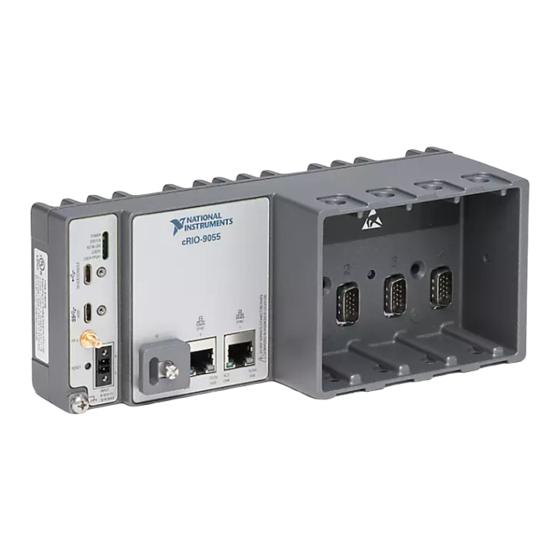
Figure 2. cRIO-905x Front Panel 1. LEDs 6. Power Connector 2. USB 2.0 Type-C Device Port with Console Out 7. Grounding Screw 3. USB 3.1 Type-C Host 8. MicroSD Card Removable Storage 4. PFI 0 9. RJ-45 Gigabit Ethernet Ports 5. -
Page 6: Connecting The Controller To Power
Connecting the Controller to Power The cRIO-905x requires a 9 V to 30 V DC external power supply. The cRIO-905x filters and regulates the supplied power and provides power for the C Series modules. 6 | ni.com | cRIO-905x Getting Started Guide... - Page 7 • Screwdriver, 2.54 mm (0.10 in.) flathead • Power supply, 9 V to 30 V, 60 W minimum NI recommends the power supplies listed in the following table for the cRIO-905x. Table 2. NI Power Supplies Power Supply Part Number...
-
Page 8: Connecting The Controller To The Host Computer
Port with Console Out. Connect the other end of the USB cable (Type-A) to the host computer. The device driver software automatically detects the cRIO-905x. Select Configure and install software to this device. 8 | ni.com | cRIO-905x Getting Started Guide... -
Page 9: Discovering The Controller In Max
If the device driver software does not detect the cRIO-905x, verify that you installed the appropriate NI software in the correct order on the host computer as described in Installing Software on the Host Computer. Discovering the Controller in MAX Complete the following steps to find the cRIO-905x controller in MAX. -
Page 10: Setting A System Password
Click the OK button. Click the Set Permissions button in the toolbar. The NI Web-Based Configuration and Monitoring utility opens in your default browser and is where you set the password. If you have not installed Microsoft Silverlight, NI Web-based Configuration & Monitoring prompts you to do so. -
Page 11: Installing Software On The Controller
To set a password for your system, refer to Setting a System Password. Select the recommended software set for your LabVIEW and NI-RIO Device Drivers versions. Click Next. Select any additional software from the list of software add-ons, if needed. -
Page 12: Testing Your Controller In Max
(MAX) to confirm that your cRIO-905x is communicating with your system. Note MAX test panels are only available for systems running NI-DAQmx driver software with supported C Series modules installed, and with modules deployed in the Real-Time (NI-DAQmx) programming mode. For additional information, refer Installing Software on the Host Computer and "Choosing Your Programming... - Page 13 Right-click any module and select Test Panels, or select Test Panels from the main configuration window options. Note If the module you select is not deployed in Real-Time (NI-DAQmx) mode, you will be prompted to switch modes to view the test panel. Configure the measurement settings and click Start.
-
Page 14: Changing Module Programming Modes In Max
Expand Remote Systems in the configuration tree and locate your cRIO-905x system. Select the C Series module you wish to program. In the Settings pane, choose the Program Mode you wish to deploy the module in from the drop-down menu. 14 | ni.com | cRIO-905x Getting Started Guide... - Page 15 Click Save. The module is deployed in the program mode. Notice the module icon changes to represent the program mode. 1. Real-Time Mode 2. Real-Time Scan (IO Variables) Mode 3. LabVIEW FPGA Mode cRIO-905x Getting Started Guide | © National Instruments | 15...
-
Page 16: Troubleshooting The Controller
. The host computer communicates with the cRIO-905x over a standard Ethernet connection. • Ensure that you have the correct version of NI CompactRIO Device Drivers installed on the host computer. Visit ni.com/info and enter the Info Code for the swsupport minimum supported versions of LabVIEW and NI CompactRIO Device Drivers. -
Page 17: Verify The System Ip Configuration
Verify the System IP Configuration Complete the following steps to verify the system IP configuration of your cRIO-905x Put the cRIO-905x in safe mode and enable the Console Out feature of the USB Type-C Device Port with Console Out by holding the RESET button down for 5 seconds. The STATUS LED starts blinking three times every few seconds. -
Page 18: Status Led Indicators
& Automation Explorer (MAX) Help for information about safe mode. Blinks four times The cRIO-905x is in safe mode. The software has crashed twice and pauses without rebooting or cycling power between crashes. 18 | ni.com | cRIO-905x Getting Started Guide... -
Page 19: Using The Crio-905X In Labview
Complete the following steps to create a new LabVIEW project configured with the cRIO-905x controller. You can use LabVIEW to program in Real-Time (NI-DAQmx) or Real-Time Scan (IO Variables) modes. For applications using advanced functionality that require programming the FPGA, LabVIEW FPGA Module is required to deploy C Series modules in the LabVIEW FPGA programming mode. - Page 20 To add your system to the project, right-click the top of the project tree and select New»Targets and Devices to launch the Add Targets and Devices discovery dialog. In the Add Targets and Devices dialog, expand the Real-Time CompactRIO folder, select your system, and click OK. 20 | ni.com | cRIO-905x Getting Started Guide...
- Page 21 Note If your system is not listed, LabVIEW could not detect it on the network. Ensure that your system is properly configured with a valid IP address in Measurement & Automation Explorer. If your system is on a remote subnet, you can also select to manually enter the IP address.
-
Page 22: Deploying Your C Series Module In A Programming Mode In Labview
Real-Time Scan (IO Variables) programming mode. Your module is now in Real-Time Scan mode. Drag your C Series module back to Real-Time Resources. This indicates you plan to use your module in Real-Time (NI-DAQmx) programming mode. 22 | ni.com | cRIO-905x Getting Started Guide... -
Page 23: Adding The Crio-905X To A Labview Fpga Project
LabVIEW FPGA Module is required to program the user-accessible FPGA on the cRIO-905x or deploy C Series modules in the LabVIEW FPGA program mode. To program in Real-Time (NI-DAQmx) or Real-Time Scan (IO Variables) modes, the LabVIEW FPGA module is not required. Refer to Adding the cRIO-905x to a LabVIEW Project for more information. - Page 24 You can locate the system IP address in MAX in the System Settings for the cRIO-905x. In the LabVIEW Project Explorer, verify that your system is present in the project tree and click Finish. 24 | ni.com | cRIO-905x Getting Started Guide...
- Page 25 Right-click the cRIO-905x in the project and select Deploy All to deploy the module in the Real-Time (NI-DAQmx) programming mode. Your module is now in Real-Time (NI-DAQmx) mode. Programming Examples For information on getting started with DAQmx programming mode examples in LabVIEW FPGA, go to ni.com/info...
-
Page 26: Where To Go Next
NI. NI corporate headquarters is located at 11500 North Mopac Expressway, Austin, Texas, 78759-3504. NI also has offices located around the world. For support in the United States, create your service request at ni.com/support... - Page 27 . You can find patents.txt ni.com/patents information about end-user license agreements (EULAs) and third-party legal notices in the readme file for your NI product. Refer to the Export Compliance Information at for the NI global trade compliance policy and how ni.com/legal/export-compliance...
Need help?
Do you have a question about the cRIO-905 Series and is the answer not in the manual?
Questions and answers