Advertisement
Quick Start Guide
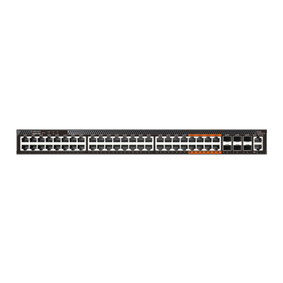
Ethernet Switch
AS4625-54T | AS4625-54P
1.
AS4625-54T/AS4625-54P (includes 2 PSUs)
2.
Rack Mounting Kit—2 brackets and 8 screws
3.
USB Micro-B to USB-A cable
4.
Four adhesive rubber feet
1
5
6
1.
48 x 1G RJ-45 ports
2.
6 x 1G/10G SFP+ ports
3.
1000BASE-T RJ-45, RJ-45 console, Micro-USB storage port
4.
2 x AC PSUs
5.
2+1 fixed redundant fans
6.
Grounding screw
1.
Reset button
2.
System — Green (OK), Amber (fault detected)
PSU1/2 — Green (OK), Amber (fault)
FAN — Green (OK), Amber (fault)
LOC — Blinking Amber (switch locator)
PoE — Green (OK), Amber (near PoE budget)
FRU Replacement
AS4625-54T
PSU Replacement
1.
Remove the power cord.
2.
Press the release latch and
remove the PSU.
3.
Install replacement PSU.
AS4625-54T
4
2
1
AS4625-54P
PSU Replacement
1.
Remove the power cord.
2.
Press the release latch and
remove the PSU.
3.
Install replacement PSU.
Package Contents
1
2
3
5.
Console cable—RJ-45 to DE-9
6.
(Optional) AC power cord
7.
Documentation—Quick Start Guide (this document) and Safety
and Regulatory Information
Overview
2
3
4
7
1.
40 x 1G RJ-45 PoE ports (30 W per port)
2.
8 x 1G RJ-45 PoE ports (90 W per port)
3.
6 x 1G/10G SFP+ ports
4.
1000BASE-T RJ-45, RJ-45 console, Micro-USB storage port
5.
2 x AC PSUs
6.
2+1 fixed redundant fans
7.
Grounding screw
Status LEDs
3
3.
RJ-45 Port LEDs: Green (link), Amber (link with PoE)
4.
SFP+ Port LEDs: Green (10G), Amber (1G)
5.
RJ-45 Management Port LEDs: Left (link), Right (activity)
– 1 –
www.edge-core.com
4
5
AS4625-54P
1
6
4
6
7
2
3
4
5
5
5
5
E072023-CS-R01
150200002546A
Advertisement
Table of Contents

Related Manuals for Edge-Core AS4625-54T


Summary of Contents for Edge-Core AS4625-54T
- Page 1 Quick Start Guide Ethernet Switch www.edge-core.com AS4625-54T | AS4625-54P Package Contents AS4625-54T/AS4625-54P (includes 2 PSUs) Console cable—RJ-45 to DE-9 Rack Mounting Kit—2 brackets and 8 screws (Optional) AC power cord USB Micro-B to USB-A cable Documentation—Quick Start Guide (this document) and Safety...
-
Page 2: Installation
(ONIE) software installer preloaded, but no software image. surface treatment). Information about compatible software can be found at Attach Grounding Wire www.edge-core.com Attach a grounding wire (#14 AWG/1.5 mm , green with yellow stripe) Note: The drawings in this document are for illustration only to the grounding point on the device’s rear panel or side panel. -
Page 3: Hardware Specifications
CB (IEC/EN 62368-1, 2nd & 3rd Ed) BSMI CNS 15598-1 Taiwan RoHS CNS 15663 Warranty Information and Technical Support Registering your product enables you to receive a more efficient warranty service. Be sure to register at www.edge-core.com. – 3 –... - Page 4 快速入門指南 乙太網路交換器 www.edge-core.com AS4625-54T | AS4625-54P 包裝內容物 AS4625-54T/AS4625-54P ( 包括 2 部 PSU) 主控台纜線 —RJ-45 到 DE-9 機櫃安裝套件 —2 個托架和 8 個螺絲 (選配) AC 電源線 USB Micro-B 轉 USB-A 纜線 文件-快速入門指南 (本文件)及安全及法規資訊 四個黏性橡膠腳墊 簡介 AS4625-54T AS4625-54P 48 x 1G RJ-45 連接埠...
- Page 5 快速入門指南 安裝 將裝置接地 警告: 為確保安全且可靠的安裝,請使用裝置隨附的配件 與螺絲。使用其他來源的配件與螺絲可能導致配件損壞。 使用未經許可配件所造成之損壞,不在保固範圍內。 注意:裝置必須安裝在限制出入地點。 附註:本裝置預先安裝了 「開放網路安裝環境 (Open Network Install Environment,ONIE) 」軟體安裝程式, 但沒有軟體圖示。關於相容軟體的資訊,可上此網站: 。 www.edge-core.com 附註:本文件中的示意圖僅供參考,可能與特定型號有 所差異。 確認機架接地 請確保機櫃正確接地,並符合國際與當地標準。確認與機櫃接地點間 有良好的電氣連接性 (無油漆或絕緣表面處理) 。 將裝置裝到機櫃中 安裝接地線 將接地線 (#14 AWG/1.5 mm ,綠色及黃色條紋)安裝在裝置後面 板或側面板接地點上。接下來,將接地線另一端連接至機櫃接地。 注意:在切斷所有電源接線前,不得移除接地連接。 連接電源 使用內附的平頭 M4x8 螺絲安裝托架。 若尚未在原廠中安裝,請在裝置中安裝一或兩部 AC PSU。然後將外...
- Page 6 尺寸(寬 x 深 440 x 350.35 x 44 毫米 (17.32 x 13.79 x 1.73 英吋 ) x 高) 重量 AS4625-54T:5.8 公斤 (12.77 磅) ,含兩部 PSU AS4625-54P:6.6 公斤 (14.55 磅) ,含兩部 PSU 溫度 操作:0° C 至 45° C (32° F 至 113° F)...
Need help?
Do you have a question about the AS4625-54T and is the answer not in the manual?
Questions and answers