Advertisement
Quick Start Guide
Ethernet Switch
AS4630-54NPE | AS4630-54NPEM
1
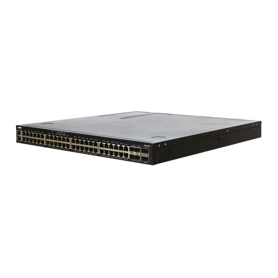
1.
AS4630-54NPE or AS4630-54NPEM Ethernet Switch
2.
Rack mounting kit—2 brackets and 8 screws
3.
2 x Power cord
4
1
2
3
1.
1x USB port
2.
1 x Management port
3.
1 x Serial console port
4.
System buttons/LEDs
5.
36 x RJ45 2.5G PoE ports
System Buttons/LEDs
STK M/S button
Reset button
System LED: Green (OK), Amber (fault)
PRI LED: Green (primary unit), Amber (secondary unit)
PSU LEDs: Green (OK), Amber (fault)
STK LEDs: Green (stacking ports active)
FAN LED: Green (OK), Amber (fault)
PoE LED: Green (OK), Amber (High PoE load)
FRU Replacement
PSU Replacement
1.
Remove the power cord.
2.
Press the release latch and
remove the PSU.
3.
Install replacement PSU with
matching airflow direction.
*150200002275A_R01*
Package Contents
6
5
Fan Tray Replacement
1.
Loosen the fan tray screw.
2.
Remove fan tray from the
chassis.
3.
Install replacement fan with
matching airflow direction.
2
3
4.
Console cable—RJ-45 to D-Sub
5.
Documentation—Quick Start Guide (this document) and Safety
and Regulatory Information
Overview
9
8
7
6.
12 x RJ45 10G PoE Ports
7.
4 x SFP28 25G ports
8.
2 x QSFP28 40G/100G uplink or stacking ports
9.
3 x Fan trays
10.
2 x AC PSUs
RJ-45 Port LEDs: Green (link), Amber (link with PoE), Blinking (activity)
SFP28 Port LEDs: White (25G), Green (10G), Blinking (activity)
QSFP28 Port LEDs: White (100G), Green (40G link), Blinking (activity)
PSU Status LED: Green (OK), Red (fault or fan failure)
Fan Tray Status LED: Green (OK), Red (fault)
– 1 –
www.edge-core.com
4
10
Port/FRU LEDs
5
E112020-MR-R01
150200002275A
Advertisement
Table of Contents

Related Manuals for Edge-Core AS4630-54NPE


Summary of Contents for Edge-Core AS4630-54NPE
- Page 1 Quick Start Guide Ethernet Switch www.edge-core.com AS4630-54NPE | AS4630-54NPEM Package Contents AS4630-54NPE or AS4630-54NPEM Ethernet Switch Console cable—RJ-45 to D-Sub Rack mounting kit—2 brackets and 8 screws Documentation—Quick Start Guide (this document) and Safety 2 x Power cord and Regulatory Information...
-
Page 2: Installation
(ONIE) software installer preloaded on the switch, but no switch software image. Information about compatible switch software Connect Power can be found at www.edge-core.com Note: Model name and approval markings are indicated on the product label located on the bottom of the device. -
Page 3: Make Network Connections
Quick Start Guide Make Network Connections Hardware Specifications Switch Chassis Size (WxDxH) 438 x 474 x 44 mm (17.24 x 18.66 x 1.73 in) Weight 8.5 kg (18.74 lb), with two installed PSUs Temperature Operating: 0° C to 45° C (32° F to 113° F) Storage: -40°... - Page 4 快速入门指南 以太网交换机 AS4630-54NPE | AS4630-54NPEM 包装清单 AS4630-54NPE AS4630-54NPEM 以太网交换机 控制台线 —RJ-45 转 D-Sub 机架安装套件 —2 个托架和 8 个螺丝 快速入门指南 安全和管制信息 文档 — (本文档)以及 2 个电源线 概述 1 x USB 端口 12 x RJ45 10G PoE 端口 1 x 管理端口 4 x SFP28 25G 端口...
- Page 5 (avant-arrière ou arrière-arrière). 交流电源 安装两个交流 PSU,并将其连接到交流电源。 注意: 此设备已在交换器上预加载了开放式网络安装环境 (ONIE),但无交换器软件映像。在以下网站可以找到有关兼 容交换机软件的信息:www.edge-core.com。 确认交换器功率 安装交换机 检查 PSU LED 指示灯 正常运行状态下, PSU1/PSU2 LED 指示灯应亮绿灯 执行初次系统启动 1.ONIE 安装程序软件 如果网络操作系统 (NOS) 安装程序位于网络服务器中,应首先使用...
- Page 6 快速入门指南 (可选)建立堆栈连接 硬件规格 交换机机箱 尺寸 (宽 x 深 x 438 x 474 x 44 mm (17.24 x 18.66 x 1.73 英寸 ) 高) 重量 8.5 kg (18.74 lb), 装有两个 PSU 温度 工作时:0° C 到 45° C (32° F 到 113° F) 存放时:-40°...
Need help?
Do you have a question about the AS4630-54NPE and is the answer not in the manual?
Questions and answers