
Related Manuals for AgileX RANGER


Summary of Contents for AgileX RANGER
- Page 1 RANGER User Manual RANGER AgileX Robotics Team User Manual V.2.0.1 2023.08 Document version Version Date Edited by Reviewer Notes 2022/10/1 V1.0.0 何士玉 first draft 1 / 6 5...
- Page 2 A robot system that uses the RANGER should be designed and used in compliance with the safety requirements and other standards of the corresponding countries. 2 / 6 5...
- Page 3 Any users of the RANGER should comply with laws and regulations of relevant countries and ensure that there are no obvious hazards in the application of the RANGER. This includes but is not limited to the following: Responsibility ● Do a risk assessment of the robotic system that uses the RANGER.
- Page 4 ● Remote control within sight range ● The maximum load capacity of RANGER is 150KG. When using it, make sure the payload does not exceed 150KG. ● RANGER When installing an external extension, confirm the position of the center of mass of the extension to ensure that it is at the center of rotation ●...
- Page 5 ● It is recommended that the operating environment altitude does not exceed 1000M ● It is recommended that the temperature difference between day and night in the use environment does not exceed 25℃ Safety Precautions ● If you have any questions about the use process, please follow the relevant instruction manual or consult relevant technical personnel.
-
Page 6: Table Of Contents
2.3 Remote Control Instructions 3 Usage and Development 3.1 Operation 3.2 CAN Communication Protocol 3.3 Firmware Upgrade 3.4 RANGER use manual for ROS 3.5 The Github ROS development kit and user manual 3.6 The vehicle body coordinate system 4 Maintenance Instructions 4.1 Maintenance method 5 Product Size... -
Page 7: Introduction Tothe Ranger
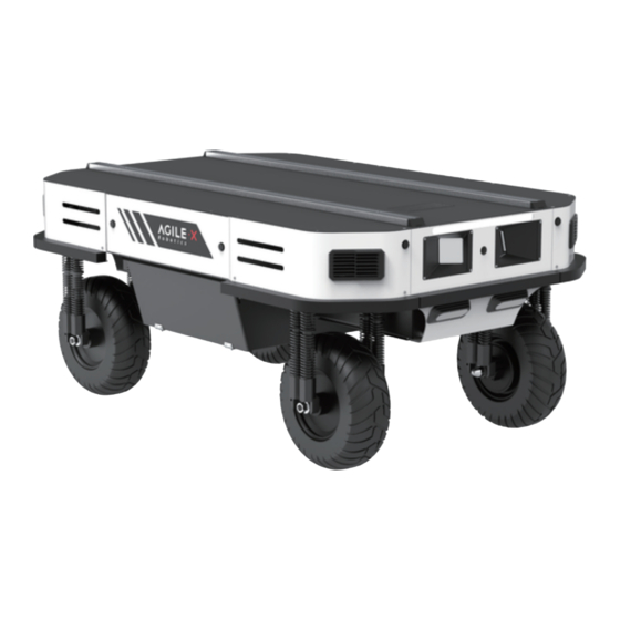
The RANGER is a programmable omnidirectional UGV (UNMANNED GROUND VEHICLE), which is a chassis with a modular design. Compared with the four-wheel differential chassis, the RANGER has obvious advantages when running on ordinary cement roads and asphalt roads. It not only has higher speed and load capacity, but also reduces the wear and tear on the structure and tires. - Page 8 Battery Type Lithium iron phosphate battery Battery parameters 48V24AH(single battery) 48v brushless toothed motor Power drive motor 600w×4 Drive motor power (w) Drive motor torque (N.M) 22NM×4 Steering motor torque 35nm×4 (N.M) Steering motor power (w) Steering motor encoder Multi-turn absolute value Drive motor encoder Hall Parking mode...
-
Page 9: Required For Development
Transportation 1.2 Required for Development The RANGER can be equipped with FS remote control when buying. Users can use it to control the 4WD chassis, complete mode switching, movement and steering. The RANGER has a standard CAN (Controller Area Network) communication interface to facilitate secondary development. -
Page 10: Status Of The Ranger
A standard aluminum extension bracket is installed on the RANGER, which is convenient for users to carry external equipment. 2.1 Status of the RANGER The user can check the status of the RANGER through its CAN message. Please refer to Table 2.1 for specific status. Status... -
Page 11: Description Of Electrical Interfaces
When the SOC (State of Charge) of the battery is lower than 15% through BMS feedback, the front and rear lights of the RANGER will flash as a Low Voltage reminder. When the battery power is detected lower than 10%, the Warning 4WD chassis will actively cut off... -
Page 12: Remote Control Instructions
When the battery voltage is lower than the safe level, it will actively cut off the power supply. Therefore, users need to pay attention to the low voltage alarm of the RANGER before reaching the critical voltage. Do not forget to charge the RANGER after use. - Page 13 (this version does not support it), and when it is turned to the middle, the ultrasonic obstacle avoidance function is turned on; when SWC is turned to the bottom, it is the parking mode, and the four-wheel four-steering is X-shaped at this time Locking (it is important to note that when the RANGER is turned off in an X-shaped parking mode, it needs to be turned on twice to start the switch button again); SWD is the switch for Motion mode:...
-
Page 14: Usage And Development
At this time, you need to open the battery cover on the back of the remote control and replace the battery. 3 Usage and Development This part mainly introduces the basic operation and usage of the RANGER, and how to carry out secondary development through the external CAN interface and the CAN bus protocol. 3.1 Operation... - Page 15 RANGER is powered off. Power on and off ● The switch marked with "STOP" at the rear of the RANGER is an emergency stop switch. Pressing it will stop the RANGER immediately and turning it clockwise will exit the emergency stop mode. Charge ●...
- Page 16 Battery replacement: RANGER itself is equipped with a 48v24ah battery. During operation, when the battery power is too low, we can open the battery panel on the right side to quickly replace the battery. 1 6 / 6 5...
- Page 17 Connection of the CAN Cable ● The 4WD chassis is shipped with an circular connector male head. The definition of its lines can refer to the figure below: Figure 3.1 Overview of the circular connector Implementation of CAN command control 1 7 / 6 5...
-
Page 18: Can Communication Protocol
Start the RANGER chassis normally. At this time, the RANGER chassis will receive instructions from the CAN interface. At the same time, the host can also analyze the status of the current chassis through the real-time data fed back by the CAN bus. For specific protocol content, refer to the CAN communication protocol. - Page 19 byte [1] Control mode unsigned int8 0x00 Standby mode 0x01 Command control mode 0x03 Remote control mode High order byte [2] byte of battery voltage Actual voltage X 10 (the unit is 0.1 unsigned int16 Low order byte [3] byte of battery voltage Highest order byte [4]...
- Page 20 Right front steering servo warning (0: bit [0] unfaulty; 1: faulty) Right rear steering servo warning (0: bit [1] unfaulty; 1: faulty) Left rear steering servo warning (0: unfaulty; bit [2] 1: faulty) byte [4] Left front steering servo warning (0: bit [3] unfaulty;...
- Page 21 bit [7] Reserved, the default value is 0 bit [0] driver status (0: unfaulty; 1: faulty) Communication connection status with bit [1] upper layer (0: unfaulty; 1: faulty) No. 5 motor driver communication status (0: bit [2] unfaulty; 1: faulty) No. 6 motor driver communication status (0: bit [3] byte [6] unfaulty;...
- Page 22 No. 3 motor driver communication status (0: bit [5] unfaulty; 1: faulty) No. 4 motor driver communication status (0: bit [6] unfaulty; 1: faulty) bit [7] Reserved, the default value is 0 The motion control feedback frame includes the current linear speed and steering angle of the vehicle.
- Page 23 byte [2] Reserved 0X00 byte [3] Reserved 0X00 byte [4] Reserved 0X00 byte [5] Reserved 0X00 High order byte of steering byte [6] angle Actual steering angle X 100 (the unit signed int16 is 0.01 °) Low order byte [7] byte of steering angle The motion control frame includes the linear speed control command and the steering angle control command.
- Page 24 Byte Meaning Data type Note Speed of the vehicle, whose unit High order is mm/s (valid value + -2500; valid byte of linear value + -1250 when the steering byte [0] speed angle > 20°; taking effect in front signed int16 byte [1] Low order and rear Ackerman mode and byte of linear...
- Page 25 High order Speed of the vehicle, whose unit byte of spin is mm/s (valid value + -1000, taking byte [4] speed effect in spin mode) signed int16 byte [5] Low order Counterclockwise spinning is byte of spin positive. speed Steering angle, whose unit is High order 0.01° (valid value +- 4000 in front byte of steering and rear Ackerman mode, valid...
- Page 26 As shown in Figure 3.2.1, when the RANGER is in front and rear Ackerman mode, the feedback steering angle is (α+β)/2, left steering is negative, and right steering is positive; the feedback speed is the average value of the four wheels speed (that is, the linear speed of the chassis),...
- Page 27 Figure 3.2.2 Wheels control of the RANGER in oblique motion mode When the chassis is in the spin mode, the steering angle is a constant value , which cannot be changed. At this time, the feedback steering angle is the average value of the absolute values of α1, α2, α3, and α4.
- Page 28 Decision-making Node for the 0x421 None None and control unit chassis Data length 0x01 Byte Meaning Data type Note 0x00 Standby mode byte [0] Control mode unsigned int8 0x01 CAN command control mode Boot into standby mode by default Control mode description: when the chassis is powered on and the remote control is not connected, the control mode is standby mode.
- Page 29 Decision-making Node for the 0x441 None None and control unit chassis Data length 0x01 Byte Meaning Data type Note 0x00 Clear all non-critical faults 0x01~0x08 Clear the communication faults of No. 1~8 motor drivers respectively 0x09 Clear the battery undervoltage fault and try to restore the power supply Error clearing...
- Page 30 0x00 0x00 0x00 0x00 0x00 0x00 0x03 0xe8 In addition to the status of the chassis itself, its feedback information also includes the steering angle and speed of the four wheels, the current of the motor, the encoder information, and the temperature information.
- Page 31 High order byte of motor byte [2] current The present current of the motor, signed int16 whose unit is 0.1 A Low order byte [3] byte of motor current Highest order byte of position byte [4] High order byte [5] byte of position signed int32 The current position of the motor, byte [6] Low order whose unit is the number of pulses...
- Page 32 Data length 0x08 Byte Meaning Data type Note High order byte [0] byte of driver voltage The current driver voltage, whose unsigned int16 unit is 0.1 V Low order byte [1] byte of driver voltage High order byte [2] byte of drive temperature signed int16 The unit is 1 ℃.
- Page 33 bit[0] Power supply voltage status (0: normal; 1: too low) bit[1] Motor temperature status (0: normal; 1: over temperature) bit[2] The current status of the driver(0: normal; 1: over-current) bit[3] Driver temperature status (0: normal; 1: over temperature) byte[5] bit[4] Sensor status (0: Normal; 1: Abnormal) bit[5] Driver status (0: Normal;...
- Page 34 High order byte of steering angle of No. byte [0] 5 motor The Current steering angle, signed int16 whose unit is 0.01 ° byte [1] Low order byte of steering angle of No. 5 motor High order byte of steering angle of No. byte [2] 6 motor The Current steering angle, signed int16 whose unit is 0.01 °...
- Page 35 High order byte of steering angle of No. byte [6] 8 motor The Current steering angle, signed int16 whose unit is 0.01 ° byte [7] Low order byte of steering angle of No. 8 motor Rotational speed feedback of four wheels Command Information feedback frame of four wheels rotational speed ’...
- Page 36 High order byte of rotational speed of No. 1 motor byte [0] The current rotational speed, Low order signed int16 whose unit is mm/s byte [1] byte of rotational speed of No. 1 motor High order byte of rotational speed of No. 2 motor byte [2] The current rotational speed, signed int16 whose unit is mm/s byte [3] Low order byte of rotational...
- Page 37 High order byte of rotational speed of No. 4 motor byte [6] The current rotational speed, signed int16 whose unit is mm/s byte [7] Low order byte of rotational speed of No. 4 motor The motion mode switching command is used to change motion model of the chassis, and the details of the protocol are as follows Command ...
- Page 38 0x00 switching is completed. Whether the 0x01 in the process of chassis is in the switching motion mode process of byte [1] unsigned int8 The chassis does not respond to switching the speed control commands in the motion model process of switching motion mode. The motion mode switching command is used to change motion model of the chassis, and the details of the protocol are as follows Command ...
- Page 39 0x00 front and rear Ackerman mode (default) 0x01 oblique motion mode byte [0] Motion mode unsigned int8 0x02 spin mode 0x03 Parking mode Odometer information feedback frame is as follows Front wheel Command Odometer information feedback Node for Receive timeout Node for sending Period receiving (ms) Drive-by-wire Decision-making 0×311...
- Page 40 Front right wheel odometer highest byte Front right wheel odometer byte [4] second highest Chassis right wheel odometer byte [5] byte feedback, signed int32 byte [6] Front right wheel Unit: mm odometer byte [7] second lowest byte Front right wheel odometer lowest byte Rear wheel...
- Page 41 Rear left wheel odometer highest byte Rear left wheel odometer byte [0] second highest Chassis left wheel odometer byte [1] byte feedback, signed int32 byte [2] Rear left wheel Unit: mm odometer byte [3] second lowest byte Rear left wheel odometer lowest byte Rear...
- Page 42 Node for Receive timeout Node for sending Period receiving (ms) Drive-by-wire Decision-making 0x241 20ms None chassis and control unit Data length 0x08 Byte Meaning Data type Note bit[0-1]: SWA: 2-Upper gear, 3- Lower gear bit[2-3]: SWB: 2-Upper gear, 1- Middle gear, 3-Lower gear Remote control byte [0] unsigned int8...
- Page 43 Ultrasonic Feedback Command Command Ultrasonic Feedback Command Node for Receive timeout Node for sending Period (ms) receiving (ms) Drive-by-wire Decision-making 50ms None chassis and control unit Data length 0×08 Byte Meaning Data type Note High order byte The distance unit is nm. of the distance Positive value: valid data byte...
- Page 44 High order byte of the distance byte measured by 【 】 No. 3 ultrasonic sensor int16 Low order byte of the distance byte measured by 【 】 No. 3 ultrasonic sensor High order byte of the distance byte measured by 【...
- Page 45 Byte Meaning Data type Note The distance unit is nm. High order byte of Positive value: valid data the distance -1: the sensor is offline. byte measured by No. 【 】 -2: sensor data validation failed 5 ultrasonic -3: abnormal sensor data sensor -4: system exception int16...
- Page 46 Low order byte of the distance byte measured by No. 【 】 7 ultrasonic sensor High order byte of the distance byte measured by No. 【 】 8 ultrasonic sensor int16 Low order byte of the distance byte measured by No. 【...
- Page 47 0×00 Disable ultrasonic obstacle Set the ultrasonic avoidance byte[0] unsigned int8 obstacle 0×01 avoidance Enable ultrasonic obstacle avoidance Feedback command of ultrasonic obstacle avoidance setting Command Feedback command of ultrasonic obstacle avoidance setting Node for Receive timeout Node for sending Period ms receiving (ms)
- Page 48 Data length 0x08 Byte Meaning Data type Note Battery SOC byte [0] State of unsigned int8 Range 0~100 Charge Battery byte [1] SOH (State of unsigned int8 Range 0~100 Health) High order byte byte [2] of battery voltage unsigned int16 Unit: 0.01 V byte [3] Low order byte of battery voltage...
- Page 49 Drive-by-wire Decision-making 0x362 500ms None chassis and control unit Data length 0x04 Byte Meaning Data type Note BIT1: Overvoltage; BIT2: Undervoltage; BIT3: High byte [0] Alarm Status 1 unsigned int8 temperature; BIT4: Low temperature; BIT7: Discharge overcurrent byte [1] Alarm Status 2 unsigned int8 BIT0: Charging overcurrent BIT1: Overvoltage;...
- Page 50 Byte Meaning Data type Note byte [0] Battery SOC unsigned int8 Range 0~100 byte [1] Battery SOH unsigned int8 Range 0~100 High order byte byte [2] of battery voltage unsigned int16 Unit: 0.01 V byte [3] Low order byte of battery voltage High order byte byte [4] of battery current...
- Page 51 BIT1: Overvoltage; BIT2: Undervoltage; BIT3: High byte [0] Alarm Status 1 unsigned int8 temperature; BIT4: Low temperature; BIT7: Discharge overcurrent byte [1] Alarm Status 2 unsigned int8 BIT0: Charging overcurrent BIT1: Overvoltage; BIT2: Undervoltage; BIT3: High byte [2] Warning Status 1 unsigned int8 temperature;...
- Page 52 byte [1] Battery SOH unsigned int8 Range 0~100 High order byte byte [2] of battery voltage unsigned int16 Unit: 0.01 V byte [3] Low order byte of battery voltage High order byte byte [4] of battery current signed int16 byte [5] Low order byte Unit: 0.1 A of battery current...
- Page 53 BIT1: Overvoltage; BIT2: Undervoltage; BIT3: High byte [0] Alarm Status 1 unsigned int8 temperature; BIT4: Low temperature; BIT7: Discharge overcurrent byte [1] Alarm Status 2 unsigned int8 BIT0: Charging overcurrent BIT1: Overvoltage; BIT2: Undervoltage; BIT3: High byte [2] Warning Status 1 unsigned int8 temperature;...
- Page 54 byte [1] Battery SOH unsigned int8 Range 0~100 High order byte byte [2] of battery voltage unsigned int16 Unit: 0.01 V Low order byte byte [3] of battery voltage High order byte byte [4] of battery current signed int16 Low order byte byte [5] Unit: 0.1 A of battery current...
- Page 55 byte [1] Alarm Status 2 unsigned int8 BIT0: Charging overcurrent BIT1: Overvoltage; BIT2: Undervoltage; BIT3: High byte [2] Warning Status 1 unsigned int8 temperature; BIT4: Low temperature; BIT7: Discharge overcurrent byte [3] Warning Status 2 unsigned int8 BIT0: Charging overcurrent The feedback data of BMS for No.
- Page 56 High order byte byte [2] of battery voltage unsigned int16 Unit: 0.01 V byte [3] Low order byte of battery voltage High order byte byte [4] of battery current signed int16 byte [5] Low order byte Unit: 0.1 A of battery current High order byte of battery byte [6]...
-
Page 57: Firmware Upgrade
byte [1] Alarm Status 2 unsigned int8 BIT0: Charging overcurrent BIT1: Overvoltage; BIT2: Undervoltage; BIT3: High byte [2] Warning Status 1 unsigned int8 temperature; BIT4: Low temperature; BIT7: Discharge overcurrent byte [3] Warning Status 2 unsigned int8 BIT0: Charging overcurrent 3.3 Firmware Upgrade To facilitate users to upgrade the firmware of the 4WD chassis and bring customers a better experience, the 4WD chassis provides a hardware interface and a software for upgrading... - Page 58 2.Click the Open Serial button, and then press the power button on the car body. If the connection is successful, the version information of the main control will be recognized, as shown in the figure. 3.Click the Load Firmware File button to load the firmware to be upgraded. If the loading is successful, the firmware information will be obtained, as shown in the figure 5 8 / 6 5...
- Page 59 4.Click the node to be upgraded in the node list box, and then click Start Upgrade Firmware to start upgrading the firmware. After the upgrade is successful, a pop-up box will prompt. 5 9 / 6 5...
-
Page 60: Ranger Use Manual For Ros
CANlight CAN communication module X1 ● Laptop X1 ● AGILEX Ranger mobile robot chassis X1 ● Paired remote control FS-i6s for the AGILEX Ranger X1 ● Circular connector on the rear of the AGILEX Ranger X1 6 0 / 6 5... - Page 61 Tested Development Environment ● Ubuntu 18.04 ● ● Hardware Connection and Preparation ● Lead out the CAN cable from the top aviation plug or tail plug, and connect CAN_H and CAN_L in the CAN cable to the CAN_TO_USB adapter respectively; ● Turn on the knob switch on the chassis of the mobile robot and check whether the emergency stop switches on both sides are released;...
- Page 62 Install and use can-utils to test hardware sudo install can-utils ● If the CAN-TO-USB adapter has been connected to the RANGER and the RANGER has been powered on, the command below can be used to monitor the data from the RANGER. candump can0 ●...
-
Page 63: The Vehicle Body Coordinate System
Pay attention to the terminal printout and use the designated keys to control the ranger movement. Github ROS development package directory and usage instructions *_base:: The core node for the chassis to send and receive hierarchical CAN messages. Based on the communication mechanism of ros, it can control the movement of the chassis and read the status of the bunker through the topic. -
Page 64: Maintenance Instructions
4 Maintenance Instructions 4.1 Maintenance method The vehicle maintenance When the tires are severely worn, please replace them in time. Battery maintenance If the battery is not used for a long time, please don't forget to charge it every 2 to 3 months. 5 Product Size 6 4 / 6 5... - Page 65 6 5 / 6 5...
Need help?
Do you have a question about the RANGER and is the answer not in the manual?
Questions and answers