AgileX SCOUT MINI User Manual
Hide thumbs
Also See for SCOUT MINI:
- User manual (43 pages) ,
- User manual (41 pages) ,
- User manual (27 pages)
Table of Contents
Advertisement
Advertisement
Table of Contents

Related Manuals for AgileX SCOUT MINI


Summary of Contents for AgileX SCOUT MINI
- Page 1 SCOUT MINI AgileX Robotics Team User Manual 2020.08 V.2.0.0...
- Page 2 If you have any questions about use, please contact us at support@agilex.ai. Please follow and implement all assembly instructions and guidelines in the chapters of this manual, which is very important. Particular...
- Page 3 SCOUT MINI integrators and end customers have the responsibility to ensure compliance with the applicable laws and regulations of relevant countries, and to ensure that there are no major dangers in the complete robot application. This includes but is not limited to the following: 1.Effectiveness and responsibility...
-
Page 4: Table Of Contents
CONTENTS 1 SCOUT MINI Introduction 3.3.3 CAN message protocol 1.1 Component list 3.4 Firmware upgrade 1.2 Tech specifications 3.5 SCOUT MINI ROS Package 1.3 Requirement for development 4 Attention 2 The Basics 4.1 Battery 2.1 Robot status indication 4.2 Operational environment 2.2 Instructions on electrical interfaces... -
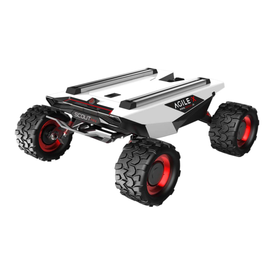
Page 5: Scout Mini Introduction
The minimum turning radius of the chassis is 0 m, and the climbing angle is close to 30 degrees. SCOUT MINI is still capable of excellent off-road performance although it is only half of SCOUT in size. -
Page 6: The Basics
12. Front fence Based on the concept of modular and intelligent design as a whole, SCOUT MINI combines filled solid tires with independent suspension as its power module, which, along with powerful hub motor, enables the development platform of SCOUT MINI robot chassis to flexibly move on different ground surfaces with high passing ability and ground adaptability. -
Page 7: Instruction On The Remote Control
2.3 Remote control instructions FS RC transmitter is an optional feature of SCOUT MINI for users to choose as actually required. With this RC transmitter designed on the left throttle in this product, users can easily control SCOUT MINI universal robot chassis. Its definitions and functions are shown in Figure 2.5 for reference. -
Page 8: Instruction On Remote Control And
Figure 3.0 Schematic Diagram of Reference Coordinate System for Vehicle Body As shown in Figure 3.0, the vehicle body of SCOUT MINI is in parallel with X axis of the established reference coordinate system.In the controller mode with RC transmitter, pushing the left rocker of the RC transmitter forward and backward respectively refers to the movement on the positive and negative directions of axis X;... -
Page 9: Getting Started
Basic operating procedure of remote control After SCOUT MINI mobile chassis is started correctly, turn on the RC transmitter and select the remote-control mode. Then, the SCOUT MINI platform motion can be controlled by the RC transmitter. -
Page 10: Can Message Protocol
SCOUT MINI adopts CAN2.0B communication standard which has a communication baud rate of 500K and Motorola message format. Via external CAN bus interface, the moving linear speed and the rotational angular speed of chassis can be controlled; SCOUT MINI will feedback the current motion status information, SCOUT MINI chassis status information, etc. - Page 11 [1]:It is available for V1.2.8 version or later, firmware upgrade is necessary for previous version. [2]:The buzzer will sound when the battery low-voltage warning , but the chassis is still controllable, and the power supply would be cut off when it comes to Low-voltage failure. The motion control feedback frame includes the feedback of moving and rotation speed of chassis.
- Page 12 Description for control mode If SCOUT MINI is power on without the connection with remote control, the default control mode is stand by, the chassis would receive the control command only and not respond to the speed command, enable the CAN control mode before using the CAN control. If you power on the remote control, then the remote control has the highest priority, the chassis would switch the control mode based on remote control only.
- Page 13 Picture3.0 Motor ID Feedback Table 3.7 Motor Rotational Speed and Current Feedback Frame Command Name Motor Rotational Speed and Current Feedback Frame Sending node Receiving node Cycle(ms) Receive-timeout(ms) 20ms None Key Unit Chassis node 0x251~0x254 Data length 0x08 Location Function Data type Description byte [0]...
- Page 14 Table 3.8 Motor Drive Status Feedback Frame Command Name Motor Status Feedback Frame Sending node Receiving node Cycle(ms) Receive-timeout(ms) None None Steer-by-wire chassis 0x261~0x264 Key unit Data length 0x08 Location Data type Description Function byte [0] Drive voltage upper 8 bit Drive voltage (0.1V) unsigned int16 byte [1]...
- Page 15 Table3.10 Light Control Frame Command Name Light control Frame Sending node Receiving node Cycle(ms) Receive-timeout(ms) Steer-by-wire chassis Key unit 0x121 500ms 100ms Data length 0x08 Location Function Data type Description 0x00 command invalid byte [0] Light control enable sign unsigned int8 0x01 Light control enable 0x00 Turn on 0x01 Turn off...
- Page 16 Table 3.12 System Version Enquiry Frame Control mode Frame Command Name Sending node Cycle(ms) Receive-timeout(ms) Receiving node None None Key Unit 0x411 Chassis node Data length 0x01 Location Data type Description Function System version enquiry byte [0] unsigned int8 0x01 Fixed value Table 3.13 System Version Enquiry Frame Command Name System Version Enquiry Frame...
- Page 17 Table 3.14 Odometer Feedback Frame Command Name Odometer Feedback Frame Cycle(ms) Receive-timeout(ms) Sending node Receiving node 0x311 None None Steer-by-wire chassis Key unit Data length 0x08 Data type Description Location Function byte [0] Left wheel odometer highest bit Left wheel odometer feedback byte [1] Left wheel odometer second highest bit signed int32...
-
Page 18: Firmware Upgrade
3.4 Firmware upgrade To facilitate the customer's upgrading of the firmware version used by SCOUT MINI and bring the customer a better experience, SCOUT MINI provides a hardware interface for the firmware upgrading, and the corresponding client software as well. A screenshot of this application is shown in Figure 3.3. -
Page 19: Scout Mini Ros Package
SCOUT MINI top aviation power socket ×1 Hardware connection and preparation Lead out the CAN wire of the SCOUT MINI top aviation plug or the tail plug, and connect CAN_H and CAN_L in the CAN wire to the CAN_TO_USB adapter respectively;... -
Page 20: Attention
4 Attention This Section includes some precautions that should be paid attention to for SCOUT MINI use and development. 4.2 Application environment precautions 4.1 Battery precautions The operating temperature of SCOUT MINI is -10℃ to 45℃; please The battery supplied with SCOUT MINI is not always fully charged do not use it below -10℃... - Page 21 Q: Is the tire wear of SCOUT MINI is normally seen when it is running? A: The tire wear of SCOUT MINI is normally seen when it is running. As SCOUT MINI is based on the four-wheel differential steering design, sliding friction and rolling friction both occur when the vehicle body rotates.
-
Page 22: Product Dimensions
6 Product Dimensions 6.1 Illustration diagram of product external dimensions... -
Page 23: Illustration Diagram Of Top Extended Support Dimensions
6.2 Illustration diagram of top extended support dimensions... - Page 24 AgileX Robotics CO., Ltd WWW.AGILEX.AI Email: sales@agilex.ai TEL:+86-769-22892150...
Need help?
Do you have a question about the SCOUT MINI and is the answer not in the manual?
Questions and answers