Advertisement
Quick Links
Advertisement

Related Manuals for Microzone MC6C


Summary of Contents for Microzone MC6C
- Page 1 MC6C Manual CH.5 CH.6 Please read carefully before use...
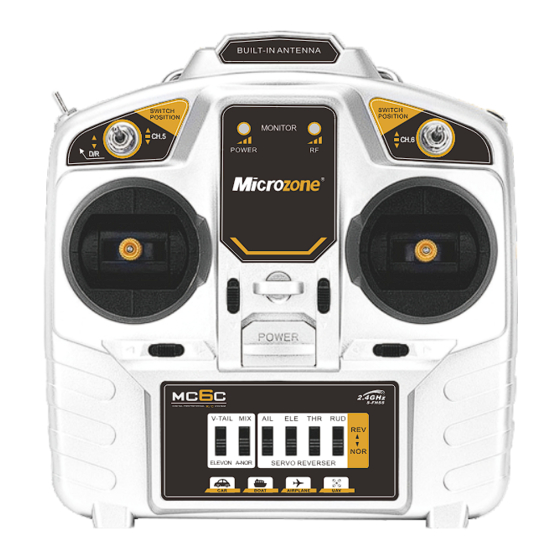
- Page 2 Transmitter Analysis MC6C antenna Power Indicator tchD/R switch signal light D/R swi channel 6 channel 5 CH.5 CH.6 Throttle fine-tuning Elevator Trim (left-hand throttle) (Left Hand Throttle) Elevator Trim Throttle fine-tuning (Right Hand Throttle) (left-hand throttle) switch rudder trim aileron trim Mixing function switch Throttle channel positive and negative settings (CH.3)
- Page 3 Transmitter parameters Model MC C Color Silver Application Fixed wing, multi-axis, vehicle, boat Number of channels Aisle Frequency band MHz- Transmit power ≤ Fine-tuning method Electronic trimming Joystick dynamic range Air control range > Adopt the latest FHSS mode in the world Modulation mode and comply with European standards Transmitter Power...
- Page 4 Detailed description Powered by: DC4-9V, You can use 4 AAA batteries to install in the battery compartment, as shown in the figure below, You can also use an external power supply to connect to the DC power socket on the right side of the remote control. When using an external power supply, please remove the battery in the battery compartment first, as shown in the figure below.
- Page 5 Shutdown: In order to ensure the safety of the model airplane and yourself, do not follow the steps below to turn off the power of the receiver first, and then turn off the power of the remote control after the motor of the model airplane stops running. Indicator light description: The orange light is the power indicator light, and the blue light is the signal light;...
- Page 6 Versions after 2023: Pull the left joystick to the upper right corner, and pull the right joystick to the upper left corner, as shown below, At the same time, turn on the power of the remote control, enter the joystick calibration state, first move the two joysticks of the remote control to the maximum, left and right, as shown in the figure below, Then pull the joystick to the middle position, as shown in the figure below, and finally pull the D/R switch to complete the calibration.
- Page 7 Solder the two square solder joints closest to the main IC with tin wire to complete the switch between left and right hands, as shown in the figure below. Versions after 2023: Remove the back cover of the remote control, and replace the retaining springs and neutral levers of the left and right sticks, as shown in the figure below.
- Page 8 Pull the left joystick to the lower left corner, and pull the right joystick to the lower right corner, as shown in the figure below, and at the same time turn on the power of the remote control to complete the switch between left and right hands. Channel description:...
- Page 9 DR switch: Large and small rudder switches, the signal output of the large rudder is 100%, that is, 1000-2000, and the output of the small rudder is 50%, that is, 1250-1750. Trimmer switch: The lower left trim switch corresponds to channel 4, and the right trim switch corresponds to channel 1; the upper left trim switch corresponds to channel 3 in left-hand mode, and channel 2 in right-hand mode;...
- Page 10 Mixing switch: The mixing control switch is pulled down to close, as shown in the figure below. Mix Mode: Pulling it to the bottom is the 1/2 channel mixing control of the three-wing wing, which is suitable for models such as the Su-27 trigger, and pulling it to the top is the 2/4 channel mixing control of the V tail, as shown in the figure below.
- Page 11 millisecond Aisle Aisle Aisle Aisle Aisle Aisle Coach function: For models with a trainer function, use a male-to-male audio cable to connect the PPM data interface of the trainer’s remote controller and the trainee’s remote controller. Turn the remote controller on the trainer switch, and the blue indicator light will flash.
-
Page 12: Receiver Parameters
Receiver Analysis MC6RE 1 M.BUS signal 6 M.BUS signal white red black external antenna orange red brown (S)信号 (-)负极 contact frequency (+)正极 Receiver parameters Model MC6RE Color Black Application Fixed wing, multi-axis, vehicle, boat Channel output 6 PWM signals, 1 SBUS signal Frequency band MHz- Receiving distance... - Page 13 Detailed description Boot: The positive and negative poles can be turned on when they are connected to the power supply. Indicator light description: Orange light flashing slowly: no signal; Orange light is always on: signal reception is normal; Orange light flashes quickly: Binding is in progress.
- Page 14 Failsafe: When the receiver loses the signal unexpectedly, it will automatically switch to the out-of-control state. When out of control, channel 1/2/4 of the receiver will output 1500us, channel 3 will output 900us, and the other channels will remain unchanged. Failsafe switching: This function is only valid for products after 2023, this operation will modify the failsafe value of channel 3 to 1500us;...
- Page 15 Precautions Read the following precautions carefully before using the remote control! 1. Please do not use it at night, thunderstorms, snow, low visibility, and other bad weather environments. 2. Please do not use it in places with snow or water; if water enters the remote control, the circuit will be short-circuited and cannot be used.
Need help?
Do you have a question about the MC6C and is the answer not in the manual?
Questions and answers
Wath Is m.bus signal