
Related Manuals for QRP Labs QMX


Summary of Contents for QRP Labs QMX
- Page 1 QMX: QRP Labs Multimode Xcvr (transceiver) Operating manual, firmware 1.00_012, 05-Dec-2023 QMX operating manual; firmware 1_00_012...
-
Page 2: Table Of Contents
5.16 Protection menu..............................40 5.17 System config..............................41 5.18 Hardware tests..............................46 5.19 Factory Reset..............................47 5.20 Update firmware...............................48 6. Operating QMX on digital modes..........................49 7. Firmware Update procedure.............................56 8. Terminal Applications..............................60 8.1 PC terminal emulator............................60 8.2 Entering terminal applications mode........................61 8.3 Exiting terminal applications mode........................61 8.4 Configuration menu.............................62... - Page 3 8.7 PC and CAT menu...............................76 8.7.1 System config..............................77 8.7.2 Input Analysis..............................77 8.7.3 CAT command test............................81 8.7.4 CAT monitor..............................86 8.7.5 Log file................................86 8.8 System menu..............................89 8.9 Exit terminal................................89 9. Resources.................................. 90 10. Document Revision History.............................90 QMX operating manual; firmware 1_00_012...
-
Page 4: Overview Of Features
QMX is a standalone CW transceiver, or a Digimodes modem You can use QMX on its own, plugging in earphones, power supply, paddle and antenna and operating CW; or, you can connect it to a PC with a single USB-C cable, to provide CAT control and Digital audio to the PC and use it with WSJT-X or other programs for single-tone FSK digital modes (not suitable for PSK31 and phase shift modes until SSB is implemented). - Page 5 A real-time clock can be displayed at the bottom right of the LCD. The time can be set by connecting a GPS receiver such as the QRP Labs QLG2 temporarily to the QMX. When power is disconnected from the QMX, the time is lost and will start at 00:00 at next power-up.
- Page 6 GPS Interface The QMX kit has a GPS interface, which is used for calibration, setting the real time clock, and for frequency and time discipline and locator setting during WSPR operation. The GPS interface (1pps and 9600 baud serial data) shares the same pins as the paddle dit and dah signals (necessary due to limited processor I/O).
-
Page 7: Connectors
Here the 1pps signal from the GPS must be connected to the 3.5mm jack “tip” connection, and the serial data (9600 baud) to the “ring” connection. In QMX these signals are 3.3V logic level; however they are connected to 5V-tolerant I/O pins on the microcontroller so 5V logic level will also work fine. - Page 8 Note that the QMX cannot supply +5V to the GPS module power supply, and in this regard the GPS interface differs from that of the QRP Labs QCX-series transceivers. So you need to arrange a separate 5V power supply for the QLG2 GPS (for example).
- Page 9 Additionally they may be configured to also be active during receive – which may be used to control some external switching for example. Note that the two outputs have 220-ohm resistors in series, to protect internal QMX circuits in the case of short-circuits.
-
Page 10: Display Elements
When RIT is non-zero, and when not in SPLIT mode, the reception frequency is the transmit VFO frequency (which may be VFO A or B) plus the RIT (which may be a negative offset). QMX operating manual; firmware 1_00_012... -
Page 11: Operator Controls
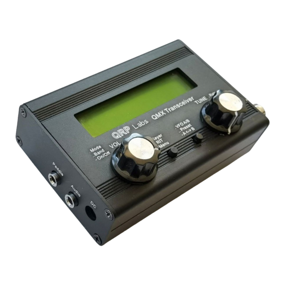
HH:MM format; it can be set manually or via GPS serial data stream parsing (UT). 4. Operator Controls This diagram shows the operating controls of the QMX. There are two rotary encoders at left and right, and two push-buttons in the center. The main function of the left rotary encoder is Volume adjustment, and that of the right rotary encoder is Tuning. -
Page 12: Tune Rate
Each of the buttons may be pressed once, pressed twice (a double-click) or pressed for a long-hold. This facilitates three different functions for each button. The laser-etched captions on the QMX front panel act as a reminder of the main functions of the various buttons and controls. -
Page 13: Rit
VFO B is active as transmit and receive VFO; if non-zero, RIT is applied during receive Split: VFO A is used for receive, VFO B is used for transmit; RIT is ignored completely Split mode is often used by DX stations, they transmit and receive on separate frequencies. QMX operating manual; firmware 1_00_012... -
Page 14: Vfo A/B Operations
In order to send a pre-saved message, press the TUNE knob with a single long press. The first of the saved messages is shown on the screen, for example if a CQ call is stored in Message 1, you may have something like this: QMX operating manual; firmware 1_00_012... -
Page 15: Menu System
The menus are organised into groups as follows: Audio Presets Messages CW Keyer CW Decoder Digi interface Beacon Display/Controls Protection System config Hardware tests Factory reset Update firmware QMX operating manual; firmware 1_00_012... -
Page 16: Saving Current Operating Parameters (Vfo Frequency Etc)
VFO frequency. Saving current operating parameters (VFO frequency etc) When you power down QMX by pressing the VOL knob, the display will show “Shut down” briefly before powering down QMX. At this time, various important operating conditions of the transceiver are stored in non-volatile storage (EEPROM) that is retained while the power is off. -
Page 17: Editing A List Parameter
When editing a number parameter, the cursor underline appears under the currently edited digit. The cursor starts at the far left (most significant digit). The TUNE knob adjusts the selected digit. The operation is very similar to tuning a VFO in ordinary operation. QMX operating manual; firmware 1_00_012... -
Page 18: Editing A Text Parameter
It is also possible to edit a text parameter entirely with the buttons and rotary encoder, though this is usually a slower way to edit text parameters. Owners of the QRP Labs Ultimate3S (or earlier) QRSS/WSPR transmitter kits will already be familiar with this style of editing text. -
Page 19: Audio Menu
Available values are 0.25dB, 0.5dB, 1dB, 2dB and 4dB. Sidetone volume Sets the sidetone volume. When editing the menu on the QMX itself, you are able to close the key contacts (dit or dah) normally but no RF transmission will occur. You can use this feature to check how the sidetone sounds and select a comfortable volume. -
Page 20: Frequency Presets Menu
“Select” button. Now you can edit the message text in one of two ways: 1) Choose each character individually from the list, using the TUNE knob to select the desired character; when you have chosen the correct character, press the “Select” button to move QMX operating manual; firmware 1_00_012... -
Page 21: Keyer Menu
The Keyer menu contains a number of configuration parameters relating to the CW keyer, which are described below. Keyer mode Iambic A The mode of the CW keyer function in the firmware. Possible modes are: Straight IAMBIC A IAMBIC B Ultimatic QMX operating manual; firmware 1_00_012... - Page 22 The keyer forces correct 1:3 ratio of dits and dahs and inter-symbol spacing, but it does not force you to wait for the correct duration of 3 dits between transmitted characters. QMX operating manual; firmware 1_00_012...
- Page 23 RF power to the antenna! During practice mode, a ‘P’ is shown in the display to the right of the frequency on the top row. Sidetone frq QMX operating manual; firmware 1_00_012...
- Page 24 GPS protection ENABLE If QMX detects a GPS receiver has been plugged into the paddle port, it will automatically set up a temporary “Practice mode” (if practice mode is not already enabled) so that the radio is not continuously keyed by the incoming GPS serial data and 1pps. A ‘G’ character appears in the display to the right of the frequency on the top row (where the ‘P’...
-
Page 25: Cw Decoder Menu
When using the keyer to enter text into message menus, the two characters are prefixed by the _ character to indicate to the QMX that when replaying the message, the following two characters should be strung together without any gap. - Page 26 With this setting you can switch “Enable TX decode” to NO and the transmit decoding is disabled. When this setting is YES, the CW decoder will decode your own keying and display it on the screen while you transmit. For an experienced CW operator that may be distracting too! Enable edit QMX operating manual; firmware 1_00_012...
-
Page 27: Digi Interface
When the audio stops, QMX will switch back to Receive automatically. The problem with this is that any system sounds on your PC, if the PC is configured to deliver these to the QMX USB sound card, will operate the transmitter and be transmitted. - Page 28 This parameter is used in conjunction with the QMX operating manual Minimum samples parameter: both conditions must be satisfied in order for an audio frequency measurement to be completed. This parameter is discussed further in the Design section of this manual in the Audio Frequency Analysis section.
-
Page 29: Beacon Menu
CW, QRSS, DFCW, FSKCW, Hellscreiber (full speed and slow FSK), WSPR, JT9, JT65, ISCAT, Opera and PI4. The vast majority of people use the Ultimate3S kit for WSPR operation. Since it costs nothing (no extra hardware, at least) to add this functionality to the QMX transceiver, why not! Let’s do it! The CW transceiver beacon function therefore contains a simplified WSPR implementation which can transmit standard WSPR messages. - Page 30 14:55:31 UT and the next frame will start at 14:56:01. 14,097,140 WSPR 14:55:31 < 56 When a GPS unit is connected, the firmware automatically uses the 1 pulse-per-second signal to measure the transmit frequency and compensate for any inaccuracy due to calibration error or QMX operating manual; firmware 1_00_012...
- Page 31 WSPR decoding takes place in the WSPR program by K1JT (see http://physics.princeton.edu/pulsar/K1JT/wspr.html ). Below is a screenshot showing the WSPR 2.0 screen following reception of a few transmissions (output frequency = 1,500Hz, Frame = 02, Start = 00). QMX operating manual; firmware 1_00_012...
- Page 32 NOT have the GPS connected, while operating the radio as an ordinary CW transceiver. If you do, the GPS serial data and 1pps will key the transmitter! Disconnect the GPS before using the radio as a CW transceiver. The following sections describe the configuration parameters in the Beacon menu. QMX operating manual; firmware 1_00_012...
- Page 33 200Hz sub-band. QMX uses a 25MHz TCXO reference which is normally within a few Hz, so accuracy of the transmission frequency is not normally an issue, even with no calibration.
- Page 34 One character which can be A-Z or 0-9 or a SPACE One character which can be A-Z or 0-9 One character which must be a number 0-9 Three characters which can be A-Z or a SPACE QMX operating manual; firmware 1_00_012...
- Page 35 47, 50, 53, 57 and 60dBm. If you specify a value not in this list, then an error message will be generated on exiting the configuration menu system. In this example, the configured value is 37dBm which corresponds to 5 watts of RF transmitter output. QMX operating manual; firmware 1_00_012...
-
Page 36: Display/Controls Menu
4.0. Each column of pixels is equivalent to an SWR increment of 0.2. In this example (right), power (top half of display characters) is 3.6W and SWR is 1.8. Power and SWR measurements should not be assumed to be high accuracy but are a useful indication. QMX operating manual; firmware 1_00_012... - Page 37 3 bars: 8.00V to 8.99V 2 bars: 7.00V to 7.99V 1 bar: 6.00V to 6.99V Empty: Below 6V (NOTE: QMX should not be operated at above 12V or below 6V). QMX operating manual; firmware 1_00_012...
- Page 38 1_00_009. S-meter step This NUMBER parameter effectively defines the sensitivity of the S-meter in legacy QCX-series transceivers. When the S-meter is implemented in the QMX firmware, this parameter will become obsolete. It can be ignored for now. Custom splash You can use this configuration to display your own customized “Splash”...
- Page 39 When set to ON, a real time clock is displayed in the bottom right part of the screen during operation. The time is NOT maintained when the QMX is powered down. You may set the clock by connecting a GPS such as the QRP Labs QLG2. Remember that the GPS and the paddle share the same microcontroller inputs (see schematic) and therefore the GPS signals key the transmitter.
-
Page 40: Protection Menu
When enabled, if a GPS is connected to the paddle port, keying of the transmitter is automatically prevented; this parameter is also available in the Keyer menu, please refer to the Keyer menu description of this parameter above. QMX operating manual; firmware 1_00_012... -
Page 41: System Config
Band version 80-20m Displays the band version of your QMX. You will have selected this at first power-up of your QMX. You can change it in this menu but the Band Configuration and other parameters will not be changed to reflect it; if you have chosen the incorrect band version at power-up and wish to reset the configuration appropriately for the version you built, the best way to do this is using the Factory Reset feature. - Page 42 QRP Labs website to help you to use the WSPRnet reporting network to determine your operating frequency quite accurately. To use these tools, simply use WSJT-X and QMX to operate as a 20m WSPR reporter (receiver) for several minutes, then look at this page: https://qrp-labs.com/images/wsprnet/rxerror.html Look for your callsign in the list, which shows the error in your reception reports (operating frequency error).
- Page 43 Japanese limits DISABLE When this setting is enabled, QMX will refuse to go into transmit mode if the specified synthesis frequency is outside the Japanese band limits as specified in the JARL bandplans document https://www.jarl.org/English/6_Band_Plan/JapaneseAmateurBandplans20200421.pdf. This setting is useful for Japanese license regulations compliance.
- Page 44 Selecting this (by pressing the left button) enters the Advanced configuration sub-menu. Ordinarily you should not need to change anything in this menu, and doing so may damage your QMX! It is highly recommended NOT to change anything in the Anvanced configuration sub-menu unless you really understand the consequences of your actions.
- Page 45 I am grateful to John Dzbrozek KJ4A for suggestion this feature as a result of his PA simulations and subsequent theoretical analysis. If you select “DISABLE” for this feature it will not damage your QMX but it may not optimize Receiver performance.
-
Page 46: Hardware Tests
5.18 Hardware tests The hardware tests menu provides access to several application tools designed to allow you to optimize and test your QMX hardware GPS Viewer GPS viewer Currently in firmware 1_00_009 the GPS viewer is the only hardware test tool available on the LCD. -
Page 47: Factory Reset
After pressing the Select button to activate the Factory reset, the screen will ask you if you’re Sure? Press the TUNE knob to confirm. Factory reset takes a few seconds while the entire EEPROM contents are written. QMX operating manual; firmware 1_00_012... -
Page 48: Update Firmware
5.20 Update firmware This menu item can be used to reboot QMX in the bootloader mode, activating the QRP Labs Firmware Update procedure (QFU). Again it is implemented as a two-step process. Update firmware Sure? Click Tune After pressing the Select button to activate the firmware update, the screen will ask you if you’re Sure? Press the TUNE knob to confirm. -
Page 49: Operating Qmx On Digital Modes
PC and the QMX. Naturally you need a power supply and the antenna connection too. QMX must be set to Digital mode, to be able to use the PC and QMX combination for digital modes! Press the VOL knob to change the mode on QMX. - Page 50 These commands are similar as used for Modem Manager service. WSJT-X configuration Next it is necessary to set up WSJT-X to communicate with QMX. We will use WSJT-X as the example, because it will be what most people are using. But other software will be identical (for example JS8Call) or similar.
- Page 51 Unfortunately unlike the USB Sound, the serial port name doesn’t contain the text “QMX”. If you are unsure which port to choose for QMX, the easy way to find this is as follows. Unplug QMX. Restart WSJT-X. Look in Settings -> Radio and make a note of the list of serial devices.
- Page 52 QMX using CAT commands that are not supported by QMX. In the section of this manual on the CAT Test utility (in the QMX Terminal applications), you will find a listing of the CAT commands supported by QMX. Another useful utility is the log file, which will let you record all CAT commands received and investigate any issues.
- Page 53 PC, is when the Pwr is at the maximum setting. There is no point to using any setting other than maximum, because QMX only ever transmits at full power (5W), there is no way for it to transmit at a lower power output under command of WSJT-X.
- Page 54 QMX has no such LED. However, QMX has an indicator on the top left character of the LCD, under the ‘A’ symbol of VFO Note that the transceiver must be put into DIGI mode before attempting digital transmissions from WSJT-X otherwise they’re just ignored.
- Page 55 QMX will show you the master volume level, and it needs to be set to 100% (not more, not less). There’s a similar thing on Windows OS.
-
Page 56: Firmware Update Procedure
This QMX manual is not the place to include tutorials on various digi mode operation or particular application software such as WSJT-X, such guides are readily available and written very much more thoroughly than I could hope to achieve! Firmware Update procedure On occasion QRP Labs may make available updated firmware for QMX, in order to deliver bug fixes or functionality enhancements. - Page 57 EEPROM contents: the QMX configuration and log file (if enabled). Again, you can read the file from QMX or write a new one to QMX, simply by dragging files in your file manager application.
- Page 58 Or copy and paste it, however you wish. The file on the QRP Labs website is a ZIPPED file, please be sure to unzip it to get the .QMX file before copying it to QMX.
- Page 59 The QMX firmware is 256-bit AES encrypted and this means: The encrypted QMX firmware file will only work on a QRP Labs QMX board, it cannot be • installed on any other board, even one containing the same processor. No other firmware file will work on the QRP Labs QMX board except an official QRP Labs •...
-
Page 60: Terminal Applications
Linux, software installation procedures etc. Instead, all the applications are hosted and coded in the QMX itself. The terminal emulator is only used to display the results. This keeps things simple and low maintenance. After all, the terminal applications are useful bonus features rather than core QMX functionality. -
Page 61: Entering Terminal Applications Mode
CAT command mode, use the cursor keys to scroll down to the “Exit terminal” option at the bottom of the main menu, and press Enter. The screen is now cleared, and QMX is back in CAT command mode. Only then should you close the terminal emulator window. -
Page 62: Configuration Menu
“configuration”. The configuration menu shows a list of sub-menus which closely correspond to the menus available on the QMX LCD itself, which were described in a previous section of this manual. In fact, the menus are driven from the same code module and menu structure;... -
Page 63: Band Configuration
The Band Configuration screen allows specification of all parameters that are handled per-band. This screen is populated by default with the correct information to set QMX up for 5-band operation on 80, 60, 40, 30 and 20m (See above). However, if you wish to experiment with other bands (which will require hardware modifications to Receiver Band Pass Filter and Transmitter Low Pass Filter component values –... - Page 64 Remember, the 50W PA is a SINGLE BAND amplifier so should only be used on the QMX with a single band, unless you are going to build an external switched Low Pass Filter. Also remember that the 50W QCX-series amplifier is designed for CW operation and not suitable for the high duty cycle of digital modes;...
-
Page 65: Hardware Tests Menu
The hardware tests menu contains several very useful tools which can be used to optimize your QMX, diagnose faults, and learn more about the QMX. The Band Configuration application is also available on this menu, to make it easier to make changes if you need to while using the tools. -
Page 66: Audio Filter Sweep
50 Hz steps up to and including 3850 Hz. The RF frequencies (“USB Dial Frequency”) used for bands are defined in the Band Configuration screen of the QMX. For example, for 80, 40, 30 and 20m are 3.573, 7.074, 10.136 and 14.074 MHz respectively. The vertical axis shows audio decibel (dB) level. -
Page 67: Rf Filter Sweep
8.6.2 RF filter sweep QMX contains its own internal signal generator, which can be used to sweep the receiver input Band Pass Filters, checking its response and center frequency. Though the difference in performance is small, the perfectionist may wish to adjust (by squeezing turns) the Band Pass Filter inductor L401 to optimize the center frequencies of the filters. - Page 68 The following images show reasonable RF sweep curves for the 20-10m version: QMX operating manual; firmware 1_00_012...
-
Page 69: Image Sweep
Any phase error in the 90-degree quadrature relationship • In QMX to date, no attempt is made to compensate for these errors. The image rejection has been found to be adequate without it. A future firmware version will likely include automatic adjustments to improve image rejection. - Page 70 When everything is correct, the three unwanted ones (the lower sideband and the USB/LSB at the image frequency) are at a much lower signal level than the wanted in-channel USB reception. QMX operating manual; firmware 1_00_012...
-
Page 71: Swr Sweep
Press To tune, this activates the transmitter at the band center frequency, at the reduced power output, and displays a realtime SWR measurement in the bottom right corner of the screen. 8.6.5 Diagnostics This is a powerful tool for diagnosing hardware problems. QMX operating manual; firmware 1_00_012... - Page 72 BIAS SMPS Similar information for the PIN diode TX forward bias current buck converter; this is only ON when you key the transmitter. In this case the measured (and calculated) current is indicated, and the QMX operating manual; firmware 1_00_012...
- Page 73 (3.3V and 5V power rails) and switches off the linear 3.3V regulator. IF there is a fault on any of this, QMX will not start; it will not start the receiver or transmitter, and will not power the LCD module or write anything to the LCD.
-
Page 74: Gps Viewer
The GPS viewer is a very cool way to display the information parsed from a connected GPS such as the QRP labs QLG2. It may not be particularly critically useful but it may be interesting to you! To make use of this application you will need to have plugged a QLG2 (or similar) GPS module into the paddle port, with 1pps and 9600 baud serial data. - Page 75 The "GPS Viewer" application is also available in the "Hardrware tests" sub-menu on the LCD/buttons/rotary encoders of the QMX itself, and contains three screens which you can scroll through by turning the right encoder. They show a general information summary screen, a Latitude/Longitude screen, and a screen showing Grid subsquare and Altitude.
-
Page 76: Pc And Cat Menu
PC and CAT menu This menu contains several items related to the PC interface and CAT commands. QMX operating manual; firmware 1_00_012... -
Page 77: System Config
8.7.2 Input Analysis The Input analysis application is one of the most interesting screens in the QMX Terminal application suite. It shows a “waterfall” which scrolls upward, with the measured audio frequency shown as a yellow block in each row, with its horizontal position determined by its frequency. The scroll rate, and the screen width, are adjustable. - Page 78 Display elements This annotated screenshot illustrates the various elements on the display. The display elements on the top row are: QMX operating manual; firmware 1_00_012...
- Page 79 Update vertical Matching Comment rate (ms) Div (s) mode Only display “10ms” in top left Only display gridlines and “20ms” in top left JT65 WSPR QMX operating manual; firmware 1_00_012...
- Page 80 Div (Hz) Demonstration of sliding frequency changes A fun and useful demonstration of the capabilities of QMX and the Input Analysis application, is to investigate the FT8 tone change transition. We know according to the WSJT-X documentation that to avoid splatter onto adjacent frequencies, WSJT-X makes a smooth transition between one tone symbol and the next.
-
Page 81: Cat Command Test
We’re talking here about tradeoffs in different aspects of performance; either way the performance is excellent and QMX keeps up with the changes in input frequency! So this is a nice confirmation of the excellent performance characteristics of QMX. - Page 82 QMX, and is old enough that it is widely supported by most software packages. Additionally QMX provides an extended set of CAT commands Q0, Q1, Q2 and so on until QB. These commands allow a host program to set and get various configuration parameters of QMX.
- Page 83 Set VFO Mode: 0, 1, 2 correspond to VFO A, VFO B or Split respectively. This is the case for both the FR and FT commands (which are nominally Receive and Transmit VFOs) because in the QMX the VFO mode use does not correspond exactly to TS-480. Get: Get Transmit VFO Mode: 0 means VFO A is used for transmit (must be VFO Mode A);...
- Page 84 Get Sample Min parameter value Q8: Get/Set Discard parameter Set: Set Discard parameter (see description elsewhere in this manual). The setting is for the current operating session only and is not written to EEPROM. Get: Get Discard parameter value QMX operating manual; firmware 1_00_012...
- Page 85 Command RX; immediately puts the radio into receive mode. It is equivalent to TQ0; SP: Get/Set Split mode Set: Sets Split mode: 0 = OFF, 1 = ON. For example “SP1;” switches QMX to split mode Get: Returns the Split state: 0 = OFF, 1 = ON.
-
Page 86: Cat Monitor
The CAT command monitor is a very plain blank screen, whose only purpose is to scroll incoming CAT commands from the CAT host, and the QMX responses. You will only be able to use this screen if you have multiple serial ports connected – one (typically the main USB Virtual COM port) to the PC host and one to a terminal (or terminal emulator on a PC, via a USB-Serial converter), running the CAT monitor terminal application. - Page 87 ERR: Band Error message “Band” In this example, a CAT command was received from WSJT-X, to set the QMX to frequency 1.84 MHz. The CAT command is “FA00001840000;” - Note that the entries in the log file are not quite in chronological order, since the VFO update event is printed BEFORE the CAT command event;...
- Page 88 Audio gain is set by the AG; CAT command RIT Down RIT down CAT RIT DN command RIT Up RIT up CAT RIT UP command Every CAT Every CAT command generates a log entry event command QMX operating manual; firmware 1_00_012...
-
Page 89: System Menu
Log file: the same log file viewer tool described in the previous section • Update firmware: puts the QMX into the QFU Bootloader mode, for firmware update. • Please refer to the section of this manual describing the firmware update procedure. -
Page 90: Resources
Resources For updates and tips relating to this kit please visit the QRP Labs QMX kit page http://qrp- labs.com/q m x For any questions regarding the assembly and operation of this kit please join the QRP Labs group, see http://groups.io/g/qrplabs...
Need help?
Do you have a question about the QMX and is the answer not in the manual?
Questions and answers