Table of Contents
Advertisement
Quick Links
Advertisement
Table of Contents

Related Manuals for Kaye ValProbe RT


Summary of Contents for Kaye ValProbe RT
- Page 1 Validation Kaye ValProbe ® User Manual M5630-EN Rev. D October 2022...
- Page 2 [No content intended for this page]...
- Page 3 Kaye ValProbe ® Process Monitoring and Validation System User Manual M5630-EN Rev. D October 2022 Copyright © 2022 Amphenol Thermometrics, Inc. 967 Windfall Road St. Marys, PA 15857-3333, USA Web: www.kayeinstruments.com...
- Page 4 [No content intended for this page]...
-
Page 5: Table Of Contents
Base Station Wakeup Magnet ................28 Wakeup Device ....................... 28 Kayetenna - Extended Antenna Cable ..............30 2.5. ValProbe RT Console / Docking Station ................ 30 Chapter 3. ValProbe RT System Connections ..............32 3.1. Direct Ethernet Connection – Static IP ................32... - Page 6 Network Ethernet Connection – DHCP................35 3.3. Resetting a Base Station....................37 Initiating a Factory Reset ..................37 Chapter 4. Initial ValProbe RT Software Setup ..............38 4.1. Introduction ........................38 4.2. Initial Log in as a Default System Administrator ............39 Setting Up Initial Administrator using Local Security and Policies ......
- Page 7 9.1. Auto Mapping Sensors ....................88 9.1. Real Time Off Study ....................... 89 9.2. Program Loggers......................92 9.3. Qualification Study Start / Stop Conditions..............93 9.4. Viewing Qualification Real-Time Displays ..............94 List View ........................95 ValProbe RT User Manual...
- Page 8 Reports Overview ..................... 119 12.2. Qualification Detailed Report..................121 12.3. Qualification Summary Report ................. 122 12.4. Graph Reports ......................123 12.5. Audit Trail Report ...................... 127 12.6. Spreadsheet Report ....................129 12.7. Pass/Fail Report ....................... 130 ValProbe RT User Manual...
- Page 9 Appendix B. Regulatory Compliance and Agency Approvals ..........154 Electrical Safety Approvals: ..................154 Radio and EMC Certification Approvals: ..............155 Ingress Protection for Kaye ValProbe RT Logger ............157 United States FDA 21 CFR Part 11 Complaint Software Application ......157 Transportation Regulations ..................158 FCC Compliance Statement ..................
- Page 10 [No content intended for this page]...
- Page 11 The first section of this manual provides an overview of the ValProbe RT hardware, instructions for creating User accounts, entering asset and equipment information, and an overview on using the ValProbe RT software. The second section of this manual covers, using the ValProbe RT, including verifying sensors, running qualification studies, and generating reports.
-
Page 12: Chapter 1. Kaye Valprobe ® Rt System
• Wakeup Device Note: The ValProbe RT product was developed to operate on dedicated networks and should always be used on networks without Internet access. Furthermore, the ValProbe RT product does not require an Internet connection to run its functionalities, as it can function independent of the Internet in either Ethernet or USB mode while in standalone operation. -
Page 13: Operational Description
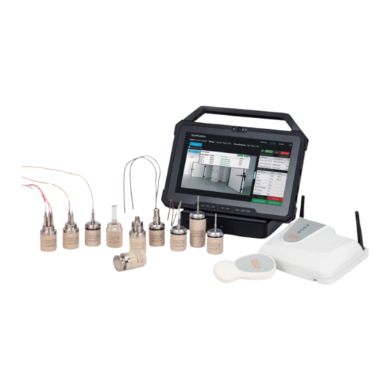
1.2. Operational Description Figure 2: The Kaye ValProbe RT System The ValProbe RT system has three main components the Base Station, the Loggers, and the Console/ Docking Station. The Base Station is the main communication link / hub between the Loggers and the Console. -
Page 14: Unpacking
As an additional option, connect the Base Station and Console / Docking Station to a network utilizing dynamic DHCP address, DHCP addresses are software configurable. The Validation Console is pre-loaded with the ValProbe RT software and is the primary interface for the operator. The User utilizes the software to configure Setups, Start/ Stop Qualifications, perform Sensor Verifications, create reports, store Validation studies, and provide a real-time display. -
Page 15: Safety Information
Base Station. Insertion of a non-rechargeable battery may cause over-heating and explosion. Utilisez UNIQUEMENT les piles secondaires (rechargeables) au lithium 3,7 V Kaye #200-166 à l'intérieur de la station de base. L'insertion d'une batterie non rechargeable peut provoquer une surchauffe et une explosion. 1.4. Safety Information Use this instrument as specified in this Manual. -
Page 16: Chapter 2. Kaye Valprobe Rt Hardware
Chapter 2: Kaye ValProbe RT Hardware Chapter 2. Kaye ValProbe RT Hardware 2.1. Kaye ValProbe RT Loggers The ValProbe RT loggers measure three critical measurands and in eight different hardware configurations: Temperature - Measures temperature from –85°C to 140°C. The bendable Temperature •... - Page 17 Chapter 2: Kaye ValProbe RT Hardware N'immergez pas l'enregistreur dans de l'huile, un liquide de nettoyage ou des détergents pendant plus de deux heures à des températures inférieures à -20°C. Après deux heures, le joint torique peut se dégrader et doit être remplacé.
-
Page 18: Temperature Rt Loggers
Chapter 2: Kaye ValProbe RT Hardware Temperature RT Loggers The Kaye ValProbe RT Temperature Logger accurately measures temperature from -85°C to 140°C using a precision Platinum RTD element. The RTD element is housed in the probe tip and ensures the following accuracy:... - Page 19 Figure 12: Five Flexible Bendable The ValProbe RT temperature Loggers provide a single solution for a variety of applications, such as steam, dry heat, ovens, incubators, stability and temperature chambers, warehouses, cryogenic chambers, lyophilizes, ultralow freezers, and other ultra-low temperature applications.
- Page 20 • Do not bend past the minimum bending radius which is 2x the diameter of the probe. To ensure that the limit is not exceeded, Kaye recommends bending the probe around a cylinder with a diameter of the Logger diameter.
- Page 21 Chapter 2: Kaye ValProbe RT Hardware Flexible Temperature RT Loggers Flexible Temperature RT Loggers are available as single, dual, or 5-sensor versions. They feature a temperature range of -85 ° to 140°C. The length of the sensor tip is 40” with a sensor tip diameter of 2.4mm, and tip length of 25mm;...
-
Page 22: Pressure/Temperature Loggers
Chapter 2: Kaye ValProbe RT Hardware Pressure/Temperature Loggers The ValProbe RT Pressure/Temperature Logger (X2532-RT) can measure pressure from 0 to 5 Bar absolute using a strain gage pressure sensor, and temperature from 0°C to 140°C using a precision Platinum RTD element. -
Page 23: Humidity Loggers
Chapter 2: Kaye ValProbe RT Hardware Humidity Loggers The Kaye ValProbe T/H Logger (model X2520) utilizes a field replaceable digital sensor to accurately measure Temperature and Humidity from 0C° to 70C° and 15% to 95% relative humidity. The accuracy is ±0.15C° for temperature and up to ±2% accuracy. The Humidity logger includes a removable filter cap and a one-meter extension cable for verifying the temperature sensor inside a dry block. -
Page 24: Insulating Canister For High Temperatures
Chapter 2: Kaye ValProbe RT Hardware Insulating Canister for High Temperatures The Kaye ValProbe RT Insulating Canister (Part Number X2545) enables operation of bendable Temperature Loggers from up to 400°C, by ensuring that the Logger base does not exceed 140°C. - Page 25 Chapter 2: Kaye ValProbe RT Hardware Table 2 displays the length of time a Logger can remain in a chamber with the internal Insulating Canister temperature remaining below 140°C. Table 2: Logger Time Inside Canister Note: The table below assumes the Logger and Insulating Canister (including the cylinder) were initially at room temperature before being placed in the chamber and that the oven is stable.
-
Page 26: Measurement Range And Accuracy
±0.15°C 2.2. Data Collection Each Kaye ValProbe RT Logger collects and stores up to 100,000 data samples per sensor in onboard Logger memory at a User-specified sample rate. If the Loggers reaches 100,000 samples, then the Logger stops collecting any further data. Data stored in the Logger is stored in non–volatile memory and is retained until a new Qualification or Verification is loaded. -
Page 27: Logger Battery
Chapter 2: Kaye ValProbe RT Hardware 2.3. Logger Battery The Kaye ValProbe RT Logger contains a field-replaceable 3.6 VDC, Lithium Thionyl Chloride ½ AA battery. WARNING! To prevent ignition in a hazardous atmosphere, the battery must be changed only in an area known to be non-hazardous. -
Page 28: Battery Estimator
Battery Estimator Figure 22: Battery Estimation Screen The Kaye ValProbe RT software tracks each Logger's battery life to within 10% of a potential low-voltage occurrence to help prevent interrupted or incomplete studies. When determining the battery life remaining, the software bases its calculations on the assumption that the battery can supply a predictable amount of energy (mAh) over the temperature range. -
Page 29: Battery Replacement
Chapter 2: Kaye ValProbe RT Hardware Battery Replacement Kaye recommends replacing the battery when there is 10% battery life remaining. The battery percentage indicator (text color) is based on the battery percentage value, between 0%-19% in Red, 20% to 49% in Orange, and 50% to 100% in Green. - Page 30 Whenever opening a Logger, replace the cup O-ring to ensure that the Logger maintains its seal. The ValProbe RT battery replacement kit contains two types of O-rings. For temperature ranges from –85 to 140ºC, use the orange (silicone material) O-ring.
- Page 31 Chapter 2: Kaye ValProbe RT Hardware • Once the battery is installed, a small red LED on the top edge of the board blinks three times to confirm that the Logger is powered on. If the LED light does not blink, follow the important note below to troubleshoot.
- Page 32 Chapter 2: Kaye ValProbe RT Hardware • From the Logger Configuration screen, select the Loggers and then Battery Reset. Figure 28: Select Loggers • Once the Loggers Status window displays, select the Loggers to reset from the lower left dropdown in the Logger Reset screen, and select Battery Reset.
-
Page 33: Kaye Valprobe Rt Base Station
2.4. Kaye ValProbe RT Base Station Base Station Overview The ValProbe RT Base Station acts as the central hub and communications link between the wireless Loggers and the ValProbe RT Console /software. The Base Station is responsible for establishing and maintaining wireless communications with the Loggers utilizing a 2.4GHz Star network with a proprietary and encrypted (AES128) protocol compliant to IEEE 802.15.4... -
Page 34: Base Station Irtd / Bath Connections
Figure 33: IRTD / Kaye Bath Connections Base Station Battery Backup Kaye ValProbe RT Base Station has battery backup for up to 60 minutes. The Base Station is powered by two 3.7V AA size rechargeable Lithium batteries. The Base Station has a built-in charger, so batteries are charged automatically when there is a main supply available to the Base Station. -
Page 35: Base Station Led Indications
Chapter 2: Kaye ValProbe RT Hardware Base Station LED Indications The Base Station LED panel provides multi-colored status indications of items such as: Figure 35: Base Station Status Panel ValProbe RT User Manual... - Page 36 Chapter 3: ValProbe RT System Connections Figure 36: Base Station LED Indication Chart ValProbe RT User Manual...
- Page 37 Chapter 3: ValProbe RT System Connections POWER LED: GREEN indicates that power input is operational. • • RED indicates an input power fail. BATTERY CHARGE LED: • GREEN indicates that battery has full capacity. • GREEN blinking indicates the battery is charging.
-
Page 38: Base Station Wakeup Magnet
Chapter 3: ValProbe RT System Connections Base Station Wakeup Magnet A powerful neodymium magnet is located behind the LED panel to the Kaye logo. The magnet is used to wake up Loggers from sleep mode prior to connection and execution of a Qualification or Verification. - Page 39 Chapter 3: ValProbe RT System Connections Magnet warning: Avoid placing any media that contains magnets or is sensitive to magnetism near this product. Magnet sensitive devices such as laptops, credit cards, or magnetic memory devices can be damaged if they are placed close to this product, so take extra care to prevent loss.
-
Page 40: Kayetenna - Extended Antenna Cable
Figure 41: ValProbe RT Console The ValProbe RT system includes a portable, hardened dedicated validation Console running Windows 10 LTSC. The ValProbe RT Console is pre-loaded with a customized Kaye core-load designed to meet data integrity and 21 CFR Part regulatory requirements, while limiting applications to those only necessary for validation needs. - Page 41 / mouse etc. The Docking Station includes a power supply (100 – 240 VAC) for charging the Console during use. The ValProbe RT Console / Software provides an interface for the ValProbe RT system to configure and control the ValProbe RT Base Station and Loggers during the validation process.
-
Page 42: Chapter 3. Valprobe Rt System Connections
Chapter 3: ValProbe RT System Connections Chapter 3. ValProbe RT System Connections The ValProbe RT system provides two options for connection from a Base Station to a Console /Docking Station: direct Ethernet connection via Static IP or network Ethernet connection via DHCP. - Page 43 Chapter 3: ValProbe RT System Connections Select the Base Station and then Connect. The Base Station should connect and move to the Select Loggers screen. Figure 44: Select Base Station Screen If the Base Station was found and communication have been established, a blue tile signifying the Base Station appears with an IP Address 192.168.99.50.
- Page 44 Chapter 3: ValProbe RT System Connections Figure 46: Setup Base Station Connection Note: If the problem persists, contact technical support. Once the Base Station is discovered and selected the BS Settings offers additional customization of your Base Station. These settings are typically set once based on desired connectivity mode.
-
Page 45: Network Ethernet Connection - Dhcp
3.2. Network Ethernet Connection – DHCP Figure 48: Network Connection The ValProbe RT can also be configured to communicate using a company or private network via DHCP. The ValProbe RT system is factory configure to utilize Direct Connection using a Static IP address of 192.168.99.55 for the Console and 192.168.99.50 for the Base Station. - Page 46 If the Base Station is not in the same sub segment or configured to another subnet mask, manually add the IP using the Add button. If Base Station discovery was unsuccessful, contact Kaye support or your company IT department.
-
Page 47: Resetting A Base Station
Chapter 3: ValProbe RT System Connections ATTENTION ! Si une station de base est configurée avec une adresse IP statique, c'est le seul moyen de communiquer avec elle. Si l'adresse IP est modifiée et que la commande "Appliquer" est envoyée, la configuration précédente n'est pas active pour toute autre connexion. -
Page 48: Chapter 4. Initial Valprobe Rt Software Setup
Chapter 4. Initial ValProbe RT Software Setup 4.1. Introduction Before utilizing the ValProbe RT software to run Qualification studies, it is necessary to initially sign in using the Default Kaye ValProbe RT account and then create a System Administrator account. The Kaye Default System Administrator account is automatically deleted when the Password Maintenance utility is exited. -
Page 49: Initial Log In As A Default System Administrator
Select Login. Once logged in, the Policies screen opens. The Policies screen is used to define if the Security and sign in for the ValProbe RT software utilizes Active Directory * for sign in or the local security and policies of the ValProbe RT ™... -
Page 50: Setting Up Initial Administrator Using Local Security And Policies
Chapter 4: Initial ValProbe RT Software Setup Setting Up Initial Administrator using Local Security and Policies When the Initial default User ID and Password are entered, the system automatically opens the Policy screen and defaults to Local security and policies. - Page 51 Chapter 4: Initial ValProbe RT Software Setup Define a System Administrator to replace the Default Kaye account. For the replacement Administrator, the New User window opens automatically. Figure 54: User Management Screen Note: Red asterisks fields are mandatory: User IDs are unique, and the passwords must follow the default rules for passwords (minimum of six characters).
-
Page 52: Setting Up Initial Administrator Using Active Director Security And Policies
At the initial Login Screen, enter “Kaye” in the User ID textbox. Note: “Kaye” is the default System Administrator User ID, and the User ID textbox is case sensitive. Please ensure that the default User ID is entered exactly as it appears above. - Page 53 Chapter 4: Initial ValProbe RT Software Setup (LDAP - “Lightweight Directory Access Protocol”, is a software protocol that stores and arranges data to make it easily searchable. Microsoft uses this for their Active Directory™* system.) Enter your Administrator User ID and Password provided by your company in the designated boxes.
- Page 54 ValProbe RT system. Each Group can be assigned a User Type which defines what permissions are granted for each member of the group. Important: For the ValProbe RT system to operate their must always be an Administrator defined group. Upon first time startup of the system, the Administrator must define and set permissions for an Administrator Group.
-
Page 55: Adding / Managing User Accounts - Local Security
Chapter 4: Initial ValProbe RT Software Setup In the User Type box, use the dropdown to select System Administrator. The Default Users Privileges appear. Select Save once completed the Default User ID and Password is deleted and the complete Policies and User Management configuration is saved locally to the console to allows Users to still utilize Active Directory™* login even when not connected to the... - Page 56 Enter a temporary password for the User in the Password textbox. The temporary password is any combination of numbers and characters. The User must change this password on their first ValProbe RT software login. Enter the temporary password again into the Confirm Password textbox.
-
Page 57: Deleting And Disabling Local Security User Accounts
Chapter 4: Initial ValProbe RT Software Setup Select the User Type dropdown to select from previously created user types or create a new User Type by typing in a new name over the previously created one in the dropdown. Select which privileges to add or remove for the new User type by selecting or deselecting the checkboxes and select Save. -
Page 58: Local Security - One Time Emergency Access
If administrator access is not possible, Kaye can provide a one-time Emergency access with the sole purpose of modifying an Administrator account. For this procedure, direct support from Kaye service is required. - Page 59 Chapter 4: Initial ValProbe RT Software Setup Select the desired group from your defined company domain. Select or type the Title for the group. Select the User Type dropdown. Figure 64: Default User Privileges Window Use the User Type dropdown to select from previously created user types or create a new User Type by typing in a new name over the previously created one in the dropdown.
-
Page 60: Setting Preferences
Chapter 4: Initial ValProbe RT Software Setup 4.3. Setting Preferences Figure 65: Preferences Tab in Administrator Menu Changing system Preferences is an Administrator task and requires an Administrator account to edit the above defaults. Any edited settings become effective immediately after selecting the Save button. -
Page 61: Hardware Maintenance
Loggers and Base Station to the factory when desired upgrades become available. All upgrades are posted on the Kaye website for download to a USB drive or computer. Use a USB inserted into a Console Docking Station to install the upgrade, or if downloading to a PC, use tools such as Remote Access to connect to the Validation Console and copy the files from a PC to the Console. - Page 62 Chapter 4: Initial ValProbe RT Software Setup RH Sensor Information Screen The ValProbe RT Temp / Humidity Logger has a digital T/H sensor with its own serial number. The Logger and sensor work as unit and are excluded from qualification studies if the sensor serial doesn’t match the serial number stored in the Logger memory.
- Page 63 Chapter 4: Initial ValProbe RT Software Setup Note the serial number which is listed below the black material. Figure 70: Sensor Serial Number Plug the extension cable into the Logger where the sensor module was removed. Connect the sensor module to the other end of the extension cable. Before proceeding, verify the serial number of the sensor is the same as Step 3.
-
Page 64: Online Help
Chapter 4: Initial ValProbe RT Software Setup Show Compatible Versions List From the Admin / Hardware Maintenance screen, select Show Compatible Versions List and select OK. A window opens displaying the firmware versions of the software, Base Station, and Loggers. -
Page 65: Chapter 5. File Management
As a dedicated validation system, the ValProbe RT system is responsible for the collection, reporting and storage of GxP files related to Thermal Validation studies. Data which is collected by the ValProbe RT system is stored locally as raw encrypted data files along with .pdf files of the reports used for analysis. -
Page 66: Sync Out
Desired Assets (includes Setups, Qualifications, Reports, and Documents) • Select OK when all selections have been completed. Unless there are existing folders, separate folders are automatically created for the different choices of data. As required, Sync Out additional folders. ValProbe RT User Manual... -
Page 67: Sync In
If selecting a folder with existing sync data as target, the copied data is merged with the existing console data. Note: It is recommended to use a separate folder for archived data, otherwise the data syncs back to the system. Figure 76: Archive ValProbe RT User Manual... -
Page 68: Valprobe Rt Convert
Also, the study files copied through the USB side port copies the files in a single file format that needs to be imported into the ValProbe RT software. Select a single data file in the browser, add a comment for easier identification if needed. If the corresponding asset is not in the system, the software creates a new asset and setup file from the information stored in the study file. - Page 69 Chapter 5: File Management Figure 78: Windows – Mapping a Drive When syncing from the software to a mapped location using the ValProbe RT software: Browse to the mapped drive. It may be required to open the drive through the file explorer and then entering windows credentials for access.
-
Page 70: Chapter 6. Equipment
Chapter 6: Equipment Chapter 6. Equipment The ValProbe RT includes a unique feature called "Equipment". Equipment is accessed from the Main Menu, by selecting the Equipment tile. Equipment provides the User with a tool that assists in tracking their Kaye calibration and verification data associated with their ValProbe RT Loggers, IRTD’s and Temperature References. -
Page 71: Manually Adding Equipment Assets
Figure 83: Equipment Assets The software then displays five VPRT Loggers, each tile contains the serial number of the Logger, the Logger type, the manufacturing Calibration date, and the Manufacturing Cal Due date. Select the desired Logger. ValProbe RT User Manual... -
Page 72: Calibration Reminder
Opening Equipment: the tiles for any equipment due for calibration are enlarged in light • blue and display the calibration due date directly within the tile. When equipment is recalibrated: the User is required to manually update the calibration • data and due date. ValProbe RT User Manual... -
Page 73: Chapter 7. Defining Assets
Figure 86: Assets Hub The Asset Hub lists the various assets validated by the ValProbe RT system. On the top text line, select each category to display the assets by: Type (sterilizer, dry heat oven, controlled temperature, etc.) up to 20 User-designated •... -
Page 74: Asset Details Screen
Copy Asset screen. It is required to enter a new name and ID for the asset. Select certain available setups to be automatically copied to the new asset. This is useful if there are multiple chambers of the same type. Figure 88: Copy Asset ValProbe RT User Manual... - Page 75 Use Copy to Drive to copy the selected setup file to a chosen drive. This is primarily used for service as requested Setup files are copied to a USB and then sent to Technical Support for review. ValProbe RT User Manual...
- Page 76 Setup file and then select the Initiate Qualification button. Selecting this button starts a qualification process. The Hardware Discovery screen displays, and the setup is transferred to the selected ValProbe RT. Qualification Selecting the Qualification tile displays a listing of all available Qualification files that have been saved.
- Page 77 Use Copy to Drive to copy the selected .pdf report to a chosen drive. For documents, the Document pane provides options to upload any .pdf files related to the asset, e.g., wiring diagrams, SOPs, or calibration certificates. ValProbe RT User Manual...
- Page 78 Delete: Permits deletion of a .pdf report (privileges required). Use Copy to Drive to copy the selected document to a chosen drive. Use the Upload Documents button to browse to the source of the desired document. ValProbe RT User Manual...
-
Page 79: Creating A New Asset
Chapter 7: Defining Assets 7.3. Creating A New Asset To enter a new asset into the ValProbe RT system, go to the Asset Hub screen and select the Plus (+) icon. The New Asset screen opens. Figure 93: New Asset Screen Enter each new asset details separately, use the textboxes and dropdowns to enter: Note: All fields highlighted with an asterisk are required fields to allow sorting of Assets. -
Page 80: Chapter 8. Defining Study Setups
Chapter 8: Defining Study Setups Chapter 8. Defining Study Setups Before running a qualification study, use the ValProbe RT software to create or modify a setup. A setup defines everything required to run a qualification study. Note: To create or modify a setup, permissions must be established and given by the System Administrator in the Admin menu (User Management tab). -
Page 81: Define Setup Screen
Note: The Setup name and number of sensors fields are mandatory. The Setup Name and Comment fields accept alphanumeric characters and spaces; the Load Description and SOP fields can also include special characters (spaces,-,_,.,?,/,and \). When all asset data is entered, select Sensors Configuration to continue. ValProbe RT User Manual... -
Page 82: Sensors Configuration Screen
Select Assign and all selected sensors will be assigned and have the defined labels. • Repeat the procedure for Pressure or Temperature if defined. To individually select sensors, select each sensor tile, then select the type of sensor, label, and number. Select Assign to complete configuration of sensor. ValProbe RT User Manual... - Page 83 Auto Numbering checkbox to enable autonumbering to the sensor description. To return to the Sensors Configuration screen select the red in the upper right corner. Select the Group Sensors tab to advance to the next screen. ValProbe RT User Manual...
-
Page 84: Understanding Groups
Using separate groups for each shelf of a freeze dryer to determine temperature • variance and having all sensors from all shelfs in a separate group for analysis. • Utilize groups to perform validation of four separate freezers at the same time each containing 12 sensors. ValProbe RT User Manual... -
Page 85: Assigning Sensors To Groups
• Edit Group: select the Pen icon inside the Group name to edit the group. Add Sensors: add additional sensors to a group. • Wiring Layout: accessible via the Book icon, enables wiring layout configuration. • ValProbe RT User Manual... - Page 86 Asset Details screen. The wiring diagram is used in Layout View during Qualification to provide live data. To clear a sensor, select the sensor label and then select Clear Sensor. When finished, select Calculations to proceed to the Calculations screen. ValProbe RT User Manual...
-
Page 87: Specifying Calculations
Sensor Label, Max-Min, Avg and Standard Deviation, Max–Avg, Avg-Min, and Cycle Time. Lethality Figure 102: Lethality Calculation Lethality calculation is typically used for most types of sterilization and Depyrogenation ovens etc. It calculates the number of equivalent minutes spent at the Base Temperature for each sensor. ValProbe RT User Manual... - Page 88 Note: If a Temp / Pressure Logger is not specified in the Sensor Configuration screen, then the Saturation Temperature of Steam cannot be defined. When all calculation definitions are completed, select Qualification Parameters to enter the Qualification parameters screen. ValProbe RT User Manual...
-
Page 89: Specifying Qualification Parameters
30 seconds, program the study start for 14:29:30. • Cycle Time does not have any duration limit, cycle time duration is dependent on sampling rate and the number of samples. The maximum number of collected samples is 100,000 per sensor. ValProbe RT User Manual... -
Page 90: Reviewing And Saving A Setup
Loggers begin to retransmit all old and current data to the Base Station and Console. 8.8. Reviewing and Saving a Setup Figure 105: Setup Review Screen After pressing Review, the Review screen opens, listing all the pertinent details about the setup that was created. ValProbe RT User Manual... -
Page 91: Modify An Existing Setup
Setup files for a specific asset are listed on the Setup screen. To modify an existing setup file: From the Setup Hub screen, select the setup file to modify. Select the Edit (pencil) button. Note: User permissions must be given to modify a setup. ValProbe RT User Manual... -
Page 92: Chapter 9. Qualification Study
(approximately 60 minutes) to perform an orderly shutdown of the system. When the Kaye ValProbe RT detects that the AC power has failed and the system is running from battery, it displays an indication on the front panel LED. -
Page 93: Initiating A Qualification Study
Ensure all Loggers to be utilized for the study are available, and near the Base Station. • Note: Kaye recommends that the User first connect, program, and Start the Qualification before placing the Loggers in the Asset. This ensure all Loggers are properly started. -
Page 94: Connecting To Base Station
Loggers. Note: To wake Loggers, swipe the supplied Wakeup Device over the base of each Logger, or swipe the base of each Logger over the Kaye Logo on the Base Station LED panel. Figure 108 Wakeup Device & Base Station... - Page 95 The “Logger Awake For” and the dropdown below it, display the amount of time Loggers will remain awake before starting the Qualification then go back to Sleep. The awake time dropdown includes times up to an hour. ValProbe RT User Manual...
-
Page 96: Re-Reading Loggers
“Warning” displays. Select the X in the top-right corner when ready to leave the screen, if you have any Loggers that have a warning, the prompt below displays, either select Yes to unselect the Loggers listed or select Continue Anyway to return to the Select Loggers screen. ValProbe RT User Manual... -
Page 97: Mapping Sensors
Use the Clear Map button to clear all group mapping and restart the process. Double select any sensor to open a Clear button, select Clear to remove the mapping for the selected sensor. ValProbe RT User Manual... -
Page 98: Auto Mapping Sensors
Figure 114: Mapping Loggers - List 9.1. Auto Mapping Sensors Additionally, the ValProbe RT System can automatically select Loggers and then map or link the specific Loggers and sensors to the Logger types defined in the Setup. To do this, select the Auto Mapping button and then check either Select All or each individual group of sensors and select OK. -
Page 99: Real Time Off Study
Qualification to open the Qualification Screen. The upper right corner displays “Study Type: Real Time Data Off” when real time data is shut off. However, the sensors display real time data up until you select Start Qual. ValProbe RT User Manual... - Page 100 Station running the study and then using the software to connect to the Base Station. Once connected to the Base Station select Show Real Time Off, any Real Time Off studies using the connected Base Station display in the window below: ValProbe RT User Manual...
- Page 101 If desired, check the checkmark of the study and then Abort to stop the selected study, otherwise, select the X to close the window. With all sensors mapped, select Program Loggers to navigate to the Programming Loggers screen. ValProbe RT User Manual...
-
Page 102: Program Loggers
Logger Time Out bar, that displays the time until the Loggers time out. When all three configuration status icons are green, the programming is complete, and the Qualification ribbon flashes yellow. Select Qualification to navigate to the Qualification screen. ValProbe RT User Manual... -
Page 103: Qualification Study Start / Stop Conditions
Lethality calculation in the Setup is configured to calculate lethality during the Exposure Cycle. The ValProbe RT system automatically controls the availability and proper sequencing of the Qual Start / Stop and Exposure Start / Stop buttons to ensure the correct order is followed (i.e. -
Page 104: Viewing Qualification Real-Time Displays
The Qualification file contains all data up to the time the study was aborted. 9.4. Viewing Qualification Real-Time Displays During a Qualification Study the ValProbe RT software offers numerous real-time and historical displays to easily evaluate and analyze the performance of the Qualification study. -
Page 105: List View
Groups defined in the setup. Select the Group name buttons above the graph to display different groups. Use the blue box with arrows to expand the Graph to full screen. Figure 124: Graph View ValProbe RT User Manual... -
Page 106: Layout View
Check the Sensor Value checkbox to display the sensor values and description in a table on screen. Selecting Edit permits editing the sensor description, select Save when finished to save any changes. Figure 126: Sensor Value in Table ValProbe RT User Manual... -
Page 107: History View
Select the Printer icon to create a Preliminary Historical Report. The report can be saved as a .Pdf or an Excel file. Note: This report is not for finalized data, it is to be used only as a historical reference of data while a study is running. Figure 128: Preliminary Historical Report ValProbe RT User Manual... -
Page 108: Chapter 10. Live Monitoring Mode
Chapter 10: Live Monitoring Mode Chapter 10. Live Monitoring Mode The ValProbe RT software offers a feature which allows Users to connect to the Base Station and Loggers and display live data. Unlike a Qualification Study no data is captured or stored, and no reports generated. -
Page 109: Live Monitoring Displays
(Console, Base Station, IRTD, Chambers, and Baths). Live collection structure (sensor and groups definition) follows the last transferred setup (to transfer a setup, first start a study). If the ValProbe RT is in monitoring status, a User can switch between List and Graph Views to display live data. -
Page 110: Hardware Communications Connections
Base Station is displayed. A green line indicates proper communications while a gray line indicates a communication problem. Figure 134: Hardware Monitoring By selecting each connected hardware icon, the software displays key information about the hardware. The IRTD provides the real-time display of the IRTD standard. ValProbe RT User Manual... - Page 111 The Humidity chamber displays the current humidity readings. Figure 135: Hardware Monitoring – Humidity To check the status of sensors, see Sensor Verification (Chapter 12). Select Stop Live from the List or Graph screen to leave Monitoring Mode. ValProbe RT User Manual...
-
Page 112: Chapter 11. Sensor Verification
Loggers are read and the system calculates based on the Loggers and IRTD/Humidity chamber data, whether the Loggers have met the defined stability and deviation criteria. The ValProbe RT system generates a verification report for each sensor and setpoint – which is stored as a .pdf file for Verification documentation printing. -
Page 113: Defining Verification Strategy And Criteria
With the ValProbe RT Loggers it is not necessary to do a Pre–Calibration of the Logger as the sensor and Logger were already calibrated to within 0.1°C at the factory and any error for the sensor is already compensated for in the factory calibration. - Page 114 If a user’s verification strategy is to perform a periodic pre-Verification and post Verification of the process qualification, then the Verification criteria is usually < 0.5°C. In this case the above-mentioned baths or Kaye Dry Blocks may be utilized as they provide adequate uncertainty as compared to the criteria.
-
Page 115: Creating A Verification Setup
Figure 136: Select the Equipment Tile Verifications are configured and initiated via the Equipment tile. Select Initiate Verification to navigate to the Verification setup screen. Figure 137: Initiate Verification Enter proper User credentials when prompted. Figure 138: Enter User Credentials ValProbe RT User Manual... -
Page 116: Temperature Verification
IRTD temperature reference stability criteria and duration • Additional time at stability to ensure sensors, Loggers, and references are stable • SOP protocol numbers (up to 50 characters) or other information • Figure 140: Setup Temperature Verification ValProbe RT User Manual... -
Page 117: Humidity Verification
SOP protocol numbers (up to 50 characters) or other information • Figure 141: Humidity Verification To enter additional setpoints or delete setpoints select on the appropriate icon. Once all setpoints and criteria are entered, save the Verification Setup under a specific name. ValProbe RT User Manual... -
Page 118: Loading A Temperature Verification Setup
Utilize the supplied cables for the connection. Power up the connected bath. IMPORTANT: If a calibration bath is not connected to the ValProbe RT Base Station, only a manual calibration can be performed. A fully automated calibration is only possible if a KAYE IRTD and a KAYE calibration bath is connected to the Base Station. - Page 119 If the System is on the network (DHCP), ensure the Console and Base Station are connected via ethernet cables to the network via ethernet connections. Select the desired Base Station tile, then select Connect. Figure 144: Select Base Station ValProbe RT User Manual...
-
Page 120: Loading A Humidity Verification Setup
Chapter 11: Sensor Verification 11.4. Loading a Humidity Verification Setup Before beginning a Humidity Verification process, load a setup into the ValProbe RT Loggers. A Humidity Chamber must be used to execute a Verification study. Please connect it to the Base Station connectors on the rear of the Base Station. -
Page 121: Selecting Sensors
Select All Loggers. The selected Loggers’ icons color changes to deep blue for temperature Loggers, purple for pressure Loggers, or dark red for humidity and the checkbox is enabled. All unselected Loggers are displayed without a checkmark. ValProbe RT User Manual... - Page 122 Note: Any unmapped Loggers will prompt a popup window asking for user confirmation on how to proceed. Select Exclude Loggers and Continue to move forward with the unmapped Logger excluded, or Re-map to remap the Logger and keep the Logger. Figure 149: Program Loggers Screen ValProbe RT User Manual...
-
Page 123: Running A Sensor Verification
Chapter 11: Sensor Verification 11.6. Running a Sensor Verification Prior to starting the verification select the Hardware button to verify the IRTD and Kaye bath drywell are displayed as connected for temperature verification or the humidity chamber for humidity verification. - Page 124 The maximum allowable change in temperature for the IRTD is fixed at 0.012°C if all temperature setpoints are equal to or greater than 0°C. If any temperature setpoint is less than 0°C, it is possible to change the IRTD stability value manually in your setup. ValProbe RT User Manual...
- Page 125 If reading becomes unstable, the process starts restarts. When duration of additional time at stability meets the criteria the textbox changes to green and the setpoint is considered fulfilled. ValProbe RT User Manual...
- Page 126 Base Station data to the Validation Console. If Read is not green, setpoints are not completed. Figure 154: Humidity Verification List View / Green Read Button The window below, displays the readout process of the Loggers. Figure 155: Read Loggers Screen Figure 156: Temperature Verification Result Screen ValProbe RT User Manual...
- Page 127 Select Result and Print to print the results of the verification • Figure 158: Sensor(s) Readings Screen The Verification Results screen displays the Pass / Fail analysis results of the Verification for each sensor. Select the setpoints to view the results for each setpoint. ValProbe RT User Manual...
-
Page 128: Reasons For Verification Failure
Time of stability of the IRTD and Logger may not overlap for a significant time • • Logger were removed from the bath / calibrator / chamber before the setpoint was reached 11.8. Verification Report Once the process is completed, a Verification report may be generated. Figure 159: Verification Reports ValProbe RT User Manual... -
Page 129: Chapter 12. Qualification Reports
Chapter 12. Qualification Reports 12.1. Reports Overview The Kaye ValProbe RT software includes a comprehensive reporting utility to generate Setup, Calibration, Qualification, and Calibration Verification reports to document the specifics of each validation study. These reports give the flexibility to perform a thorough analysis of process performance, while meeting regulatory guidelines for 21 CFR Part 11 and Data Integrity guidelines. - Page 130 Created by • Created date / time • • Asset name Asset ID • SOP # • • User comments Signature fields in the footer are configurable in the Admin / Preference screen. Figure 160: Setup Report ValProbe RT User Manual...
-
Page 131: Qualification Detailed Report
The remaining sections of the cover page include, the groups included in the report, any sensors excluded from group calculations, the sensors used in the study by serial number, and any user comments added during post-qualification reporting. ValProbe RT User Manual... -
Page 132: Qualification Summary Report
• Max spread and time of occurrence • • Min and Max accumulated Lethality and from which sensor Avg of Avg • • Max of all (Max - Min) for all sensors contained in the group. ValProbe RT User Manual... -
Page 133: Graph Reports
Use the Cycle dropdown to select defined Cycles for graphing. Use the > or < to the right of the graph to maximized to full screen or minimized the graph. ValProbe RT User Manual... - Page 134 Each measured temperature and the calculated saturation temperature do not • fluctuate more than 1 K. All measured temperatures and the calculated saturation temperature do not differ • from each other by more than 2 K. ValProbe RT User Manual...
- Page 135 The saturation temperature calculation is only available if the study includes at least one • pressure sensor along with temperature sensors. • The Equilibrium calculation is only accessible if the Qualification data storage rate is one sec. ValProbe RT User Manual...
- Page 136 Select Generate Report to create a .pdf report of the graph. Enter a custom label and select Apply. Use the option in the Summary Report to automatically include a completed study graph in the Summary report. ValProbe RT User Manual...
-
Page 137: Audit Trail Report
Chapter 12: Qualification Reports 12.5. Audit Trail Report To meet 21 CFR Part 11 and Data Integrity requirements, the ValProbe RT system includes a robust and comprehensive Audit Trail. The Audited Trail automatically captures all system and Operator actions which affect the creation, modification, deletion, or storage of GXP data and reports. - Page 138 Qualification file. Define the cycles and proceed to the Standard reports screen. Check the Audit Trail checkbox, then the required time frame and filter options using the Report Content button, to generate an Audit Report with the events related to the qualification study. ValProbe RT User Manual...
-
Page 139: Spreadsheet Report
Excel for further analysis or graphing. The file is automatically divided into numerous tabs which provide detail Qualification data. The tabs consist of: General Information Sensor Definitions Temperature Data Temperature Statistical Temperature Lethality Pressure Data Saturation P-T Messages and Comments Figure 166: Spreadsheet Report ValProbe RT User Manual... -
Page 140: Pass/Fail Report
A cycle is a defined period during the Qualification study. The ValProbe RT software allows the User in the Setup report to define cycles (i.e., Qual Start to Qual End). Cycles can also be added or modified in the Reporting Tool prior to generation of reports. - Page 141 If for example, a data point (A1) has reached the given criterion threshold, the system checks if the next data point (A2) has reached the given criterion threshold as well. In that case, the interval between the data points are counted toward the accumulated value. ValProbe RT User Manual...
- Page 142 Once the template has been selected or defined the User can select which Groups to include in the report and used for the analysis. Each Group of sensors has their own analysis and report pages. Figure 169: Template to Group Screen ValProbe RT User Manual...
- Page 143 Group maximum-minimum value for each timestamp. The criteria defines the maximum allowable spread for all timestamps during a cycle. The criterion “Passes” if all Group Max-Min temperature timestamps are equal to or less than the defined criteria. ValProbe RT User Manual...
- Page 144 The pressure sensor used as the reference is displayed. The criterion describes a steam quality band and is specified as the Min and Max allowable deviation from the measured temperature to the calculated Saturation temperature. The criterion “Passes” if all values are equal to or within the defined range. ValProbe RT User Manual...
- Page 145 If both Min and Max fields are defined the criterion “Passes” if the calculated Exposure / Hold time is equal to or within the defined range. ValProbe RT User Manual...
- Page 146 “Fail”. For additional information on the Pass/Fail Criteria report contact technical support or your local Account Manager. ValProbe RT User Manual...
- Page 147 Chapter 12: Qualification Reports Figure 171: Failed Sensors Note: Users of the Kaye Report Tool acknowledge that the pass / fail criteria included in the software is not a substitute for calculation and analysis of pass / fail criteria by a skilled technician.
-
Page 148: Generating Qualification Reports
Chapter 12: Qualification Reports 12.8. Generating Qualification Reports Before selecting a report type, the ValProbe RT software permits the User a final opportunity to verify or edit parameters such as: Start / Stop conditions (marking cycles) • Sensor groupings •... - Page 149 Qual / Exposure times. Figure 174: Mark Cycles Using Time / Marker In the edit Cycle dropdown box select Events to select an existing event or create a new event. ValProbe RT User Manual...
- Page 150 Select the button at the top right of the screen to navigate to the Cycles window. The method and functionality for defining cycles is the same as defined in Exposure Start / End. ValProbe RT User Manual...
-
Page 151: Edit Parameters
Inside the Edit Parameters screen, you can make any necessary changes to Groups and or Calculations prior to reporting. Any changes to Groups or Calculations are listed in the reports. If no changes are needed, select the Next arrow at the top of the screen to proceed. ValProbe RT User Manual... - Page 152 Time of Sterilization to display information for each. With the desired calculation selected in the right panel select Customize to open the Customization options for the calculation. Any changes to calculations are detailed in the Qualification report. ValProbe RT User Manual...
- Page 153 Lethality and Time of Sterilization New European regulation have placed and emphasis on ensuring proper steam quality when calculating lethality. For this reason, Kaye has added additional options which if checked, only calculate the Instantaneous lethality for the timestamp if the Saturation Pressure and Temperature are within defined limits set in the Time of Sterilization calculation.
-
Page 154: Report Selection
Multiple reports may be selected at one time to improve efficiency. All generated reports are formatted in .pdf. All .pdf reports are automatically saved into the Asset where the Qualification file was stored and placed in the Report tile. Figure 183: Standard Report Selection Screen ValProbe RT User Manual... - Page 155 Audit Trail – allows data duration of Audit Trail. Default is current date above. Figure 187: Audit Trail Selection Pass / Fail Criteria – permits selection of a template for use for each group. Figure 188: Pass / Fail Report Content Screen ValProbe RT User Manual...
- Page 156 This can minimize the pages printed while still providing the granularity for calculations and graphs. Select Generate Report to generate the respective report types. Figure 190: Print Rate ValProbe RT User Manual...
- Page 157 [No content intended for this page] ValProbe RT User Manual...
-
Page 158: Appendix A. Specifications
Appendix A. Specifications Appendix A. Specifications A.1 Kaye ValProbe RT System A.1.1 List of Certified Countries USA, Canada, European Union, and Puerto Rico. A.1.2 Regulatory Compliance CE, FCC and safety listed by Eurofins MET Labs, USA. A.1.3 RF System Operating Frequency and Modulation 2.4 GHz unlicensed ISM band with modulation O-QPSK (IEEE 802.15.4 complaint). -
Page 159: Kaye Valprobe Rt Base Station
LED indications on front panel and internal buzzer for status monitoring and alarms. A.2.6 Bath and IRTD Interface Ports Bath port supports to interface all Kaye brand temperature baths and IRTD port to connect IRTD-400 temperature reference standard to run calibrations. -
Page 160: Kaye Valprobe Rt Logger
A.3.6 Real Time Clock Accuracy 15 sec per 24 hours (0.0174%). Kaye ValProbe RT Temperature Logger: -85 to 140°C range. Kaye ValProbe RT Pressure Temperature Logger: 0 to 140°C range. Kaye ValProbe RT std Temperature Logger: -40 to 140°C range. A.3.7 Sensing Elements Temperature: Precision platinum RTD. - Page 161 Battery life is affected by several factors, including sample rate, transmission rate, temperature, Logger type and hours of use. Individual battery capacity can vary from one battery to another by up to 10%. A.4 Kaye ValProbe RT Temperature Logger A.4.1 Measurement Accuracy ±0.1°C from -85 to 140°C.
- Page 162 Appendix A. Specifications A.5 Kaye ValProbe RT Std Temperature Logger A.5.1 Measurement Accuracy ±0.1°C from -40 to 140°C ±0.25°C from 140 to 400°C for bendable models. A.5.2 Body Environmental Ratings: Temperature: -40 to 140°C. Temperature: -40 to 360°C with canister model.
- Page 163 Appendix A. Specifications A.7 Kaye ValProbe RT Humidity Logger A.7.1 Measurement Accuracy Temperature: Resolution: 0.01°C Accuracy: ±0.15°C from 0°C to 70°C Humidity: Resolution: 0.1% Accuracy: ±2% RH from 15% to 95% RH at 25°C to 40°C A.7.2 Environmental: Temperature: 0°C to 70°C Humidity: 15% to 95%, RH non-condensing A.7.3 Operating Range Accuracy...
-
Page 164: Appendix B. Regulatory Compliance And Agency Approvals
Kaye ValProbe RT Loggers Regulatory model number - RF3050 B.1 Electrical Safety Approvals: Kaye ValProbe RT Product Electrical safety is certified by MET Laboratories, Inc. USA and product is complaint to IECEE CB-scheme for access into international market. B.1.1 European Safety Certification Low Voltage Directive 2014/35/EU. -
Page 165: Radio And Emc Certification Approvals
Canada ICES-003 — Information Technology Equipment (Including Digital Apparatus) — Limits and Methods of Measurement. Kaye ValProbe RT est certifiée pour les normes radio et CEM de la FCC des États-Unis et de l'ISED du Canada énumérées ci-dessous : 47 CFR, FCC Part 15 Subpart C §15.247 ; General technical requirements of operation of unlicensed Radio frequency Intentional radiator devices operation within the bands 902-928 MHz, 2400-2483.5 MHz, and 5725-5850 MHz. - Page 166 émissions de bruit radioélectrique des équipements électriques et électroniques à basse tension dans la gamme de 9 kHz à 40 GHz. Canada ICES-003 - Équipement de technologie de l'information (y compris les appareils numériques) - Limites et méthodes de mesure. ValProbe RT User Manual...
-
Page 167: Ingress Protection For Kaye Valprobe Rt Logger
ISO/IEC Directives, Part 2. B.3 Ingress Protection for Kaye ValProbe RT Logger Kaye ValProbe RT Logger is certified to EN60259 / IP68 Ingress Protection standard. IP68 Ingress Protection (IP code): Degrees of protection provided by enclosures as per EN 60529:1991+A1:2000+A2:2013 standard. -
Page 168: Transportation Regulations
User to operate the device. Kaye ValProbe RT Base Station FCC ID: 2AJQZ-VPRT-BS1 Kaye ValProbe RT Logger FCC ID: 2AJQZ-VPRT-L1 FCC 47 CFR §2.1091 RF Radiation Exposure statement: This product complies with FCC 47 CFR §2.1091, Canada ISED RSS-102 and European... -
Page 169: Ised Canada Compliance Statement
1.L’appareil ne doit pas produire de brouillage; 2.L’appareil doit accepter tout brouillage radioélectrique subi, même si le brouillage est susceptible d’en compromettre le fonctionnement. Kaye ValProbe RT Base Station Canada IC: 25680-VPRTBS1 Kaye ValProbe RT Logger Canada IC: 25680-VPRTL1 B.8 EU Compliance Statement:... -
Page 170: Product Certification Labels
Appendix B. Regulatory Compliance and Agency Approvals B.9 Product Certification Labels B.9.1 Kaye ValProbe RT Base Station Label B.9.2 Kaye ValProbe RT Logger Label ValProbe RT User Manual... -
Page 171: China Compliance Statement
Appendix B. Regulatory Compliance and Agency Approvals B.10 China Compliance Statement The following China regulatory compliance statements are applicable to Kaye ValProbe RT Loggers. The specified applicable scenario, antenna type and features as well as control method shall meet the requirements of “Micropower short-range devices. -
Page 172: Australia Compliance Statement
Appendix B. Regulatory Compliance and Agency Approvals B.11 Australia Compliance Statement The Kaye ValProbe RT Base station (Regulatory model number RF3060) and Kaye ValProbe RT Loggers (Regulatory model number RF3050) are compliant with the standards made by the Australian Communications and Media Authority (ACMA). -
Page 173: Appendix C. Environnemental Compliance
The battery is marked with this symbol, which may include lettering to indicate cadmium (Cd), lead (Pb), or mercury (Hg). For proper recycling return the battery to your supplier or to a designated collection point. ValProbe RT User Manual... - Page 174 Mercury creates hazardous vapors at room temperature. Exposure to high • concentrations of mercury vapor can cause a variety of severe symptoms. Risks include chronic inflammation of mouth and gums, personality change, nervousness, fever, and rashes. ValProbe RT User Manual...
-
Page 175: Appendix D. Warranty And Returns
Upon receipt of the owner’s approval to proceed, the instrument will be repaired and returned. ValProbe RT User Manual... -
Page 176: Appendix E. Service Information
Liability is therefore excluded to that extent permitted by law. Any proprietary rights of third parties as well as existing laws and regulations must be observed by the recipient of the product on his own responsibility. ValProbe RT User Manual... - Page 177 Equipment Connect ............................... 100 Group Assigning Sensors ..........................75 Calculations ............................77 Creating ..............................75 Understanding ............................74 Kaye ValProbe Rt ............................2 Live Data, Viewing............................. 98 Manual Explanation ............................82 New Asset ..............................69 Qualification Study ..............................82 Setup Create ..............................
- Page 178 Index Calculate ............................. 114 Introduction ............................102 Stop Qualification ............................82 Verification Introduction ............................102 Setup..............................110 ValProbe RT User Manual...
- Page 179 [No content intended for this page]...
- Page 180 [No content intended for this page]...
- Page 181 www.kayeinstruments.com © 2022 Amphenol Thermometrics, Inc. All rights reserved. Technical content subject to change without notice. M5630 Rev. D October 2022...
Need help?
Do you have a question about the ValProbe RT and is the answer not in the manual?
Questions and answers