Table of Contents
Advertisement
Quick Links
Advertisement
Table of Contents

Related Manuals for Kaye ValProbe RT

Summary of Contents for Kaye ValProbe RT
- Page 1 Validation ® Kaye ValProbe User Manual MXXX-EN Rev. 1.0 May 2020...
- Page 2 [No content intended for this page]...
- Page 3 ® Kaye ValProbe Process Monitoring and Validation System User Manual M5XXX-EN Rev. 1.0 May 2020 Copyright © 2020 Amphenol Thermometrics, Inc. 967 Windfall Road St. Marys, PA 15857-3333, USA Web: www.kayeinstruments.com...
- Page 4 [No content intended for this page]...
-
Page 5: Table Of Contents
Data Collection ................. 14 2.3. Logger Battery .................. 15 2.3.1. Battery Replacement ..............16 2.4. Kaye RF ValProbe RT Base Station ..........20 2.4.1. Base Station Overview .............. 20 2.4.2. Base Station IRTD / Bath Connections ........21 2.4.3. Base Station Battery Backup ............. 21 2.4.4. - Page 6 Modify an Existing Setup ..............62 7.3. Define Setup Screen ................ 63 7.4. Sensors Configuration Screen ............64 7.5. Understanding Groups ..............65 7.6. Assigning Sensors to Groups ............66 7.7. Specifying Group Calculations ............68 Kaye ValProbe RT User Manual...
- Page 7 Specifying Qualification Study Conditions ........69 7.9. Reviewing and Changing a Setup ............ 70 Viewing Live Data ..............71 8.1. Selecting a ValProbe RT ..............71 8.2. Monitoring Live Data ................. 72 8.3. Live Data During Qualification ............73 8.4.
- Page 8 Edit Parameters Screen .............. 129 11.10. Report Selection ................. 130 11.11. Grouping Sensors ............... 131 Appendix A. Specifications ................. 135 Kaye ValProbe RT System ............. 135 A.1.1 List of Certified Countries ............135 A.1.2 Regulatory Compliance ............135 A.1.3 RF System Operating Frequency and Modulation ....135 A.1.4...
- Page 9 Contents A.1.13 Optional Extendable Base Station Antenna ......135 Kaye ValProbe RT Base Station ............ 136 A.2.1 Input Power and Adaptor Ratings ........... 136 A.2.2 Installation Category ..............136 A.2.3 Overvoltage Category and Electrical Safety Protection Class 136 A.2.4 Input DC Power On/Off Switch ..........136 A.2.5...
- Page 10 USA FCC and Canada ISED ........... 141 B.2.2 European Radio and EMC Certification Approvals:....142 Ingress Protection for Kaye ValProbe RT Logger ......142 United States FDA 21 CFR Part 11 Complaint Software Application Transportation Regulations ............143 FCC Compliance Statement ............143 ISED Canada Compliance Statement ..........
- Page 11 EU Compliance Statement: ............144 B.9 ......................144 Product Certification Labels ..............145 B.9.1 Kaye ValProbe RT Base Station Label ........145 B.9.2 Kaye ValProbe RT Logger Label ..........145 Appendix C. Environnemental Compliance ..........146 C.1 Waste Electrical and Electronic Equipment (WEEE) Directive ... 146 C.2 Battery Disposal ..................
- Page 13 About this Manual The first section of this manual provides an overview of the ValProbe RT hardware, instructions for creating user accounts, entering asset and equipment information, and an overview on using the ValProbe RT software. The second section of this manual covers, using the ValProbe RT, including verifying sensors, running qualification studies, and generating reports..
-
Page 14: Kaye Valprobe Rt System
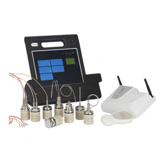
1.1. Introduction Figure 1: The Kaye ValProbe RT The Kaye ValProbe RT is a wireless real-time process validation system designed around the measurement and reporting requirements of the Life Sciences and Food industry. The wireless and real-time aspect of the system make it ideal for harsh applications where the use of wires can be difficult to access and install. -
Page 15: Operational Description
1.2. Operational Description Figure 2: The Kaye ValProbe RT System The ValProbe RT system has three main components the Base Station, the Loggers, and the Console/ Docking Station. The Base Station is the main communication link/ hub between the Loggers and the Console. -
Page 16: Unpacking
Base Station and Console / Docking Station to a network utilizing dynamic DHCP address which are software configurable. The Validation Console is pre-loaded with the ValProbe RT software and is the primary interface for the operator. The user utilizes the software to configure Setups, Start/ Stop Qualifications, perform Sensor Verifications, create reports, store Validation studies and provide real-time display. -
Page 17: Safety Information
Use this instrument as specified in this Manual. • Protection provided by the equipment may be impaired if the equipment is used in a manner not specified by Kaye. • Do not use this equipment in environments other than those listed in the Manual. -
Page 18: Kaye Valprobe Rt Hardware
0°C to 140°C. Figure 5: Kaye ValProbe RT Loggers The Kaye ValProbe RT Loggers are made from pharmaceutical grade polyether ether ketone (PEEK), 316 stainless steel, and designed for in-situ use. For example, they can be immersed in cleaning fluid or detergents, or used in harsh environments. -
Page 19: Temperature Rt Loggers
O-ring should be replaced whenever the Logger is opened. Temperature RT Loggers The Kaye ValProbe RT Temperature Logger accurately measures temperature from -85°C to 140°C using a precision Platinum RTD element. The RTD element is housed in the probe tip and ensures the following... - Page 20 Flexible Bendable Flexible The ValProbe RT Logger is a temperature logger that provides a single solution for a variety of applications, such as steam, dry heat, ovens, incubators, stability and temperature chambers, warehouses, cryogenic chambers, lyophilizes, ultralow freezers, and other ultra-low temperature applications.
- Page 21 Chapter 2: Kaye ValProbe RT Hardware Rigid Temperature RT Loggers The Rigid Temperature RT Loggers have a temperature range from -85°C to 140°C. They are a single sensor only, with a sensor length of 1.5”, 3”, 6”, or 9”, and have a diameter of 3mm / 0.118”.
- Page 22 • Do not bend past the minimum bending radius is 2x the diameter of the probe. To ensure that the limit is not exceeded, Kaye recommends bending the probe around a cylinder with a diameter of the logger diameter. •...
- Page 23 Chapter 2: Kaye ValProbe RT Hardware Flexible Temperature RT Loggers Flexible Temperature RT Loggers are available as single, dual, or 5-sensor versions. They feature a temperature range of -85 ° to 140°C. The length of the sensor is 40” with a sensor tip diameter of 2.4mm, and tip length of 25mm;...
- Page 24 Chapter 2: Kaye ValProbe RT Hardware Pressure/Temperature Loggers The ValProbe RT Pressure/Temperature Logger (X2532) can measure pressure from 0 to 5 Bar absolute using a strain gage pressure sensor, and temperature from 0°C to 140°C using a precision Platinum RTD element.
-
Page 25: Insulating Canister For High Temperatures
Chapter 2: Kaye ValProbe RT Hardware Insulating Canister for High Temperatures The Kaye ValProbe RT Insulating Canister (Part Number X2545) enables you to operate bendable Temperature Loggers from up to 360°C by ensuring that the Logger base does not exceed 140°C. - Page 26 Chapter 2: Kaye ValProbe RT Hardware Table 2 displays the length of time a Logger can remain in a chamber with the internal Insulating Canister temperature remaining below 140°C. Table 2: Logger Time Inside Canister Note: The table below assumes the Logger and Insulating Canister (including the cylinder) were initially at room temperature before being placed in the chamber and that the oven is stable.
-
Page 27: Measurement Range And Accuracy
135°C to 140°C ±25 mb 2.2. Data Collection Each Kaye ValProbe RT Logger collects and stores up to 100,000 data samples per sensor in memory at a user-specified sample rate. If the Loggers reaches 100,000 samples then the Logger stops collecting any further data. -
Page 28: Logger Battery
10%. Refer to the battery life tables in the Kaye ValProbe RT online help for the best approximation of the number of runtime hours you can expect from the battery at different sample rates and temperatures. -
Page 29: Battery Replacement
Battery Replacement Kaye recommends that you replace the battery when there is 10% battery life remaining. The battery percentage indicator (text color) is based on the battery percentage value, between 0-19% in Red, 20 to 49% in Orange, and 50% to 100% in Green. - Page 30 Figure 22: Remove the Old Battery and O-ring Install the Replacement O-ring and Battery Whenever you open a Logger, you need to replace the cup O-ring to ensure that the Logger maintains its seal. The ValProbe RT battery replacement kit contains two types of O-rings. •...
- Page 31 Chapter 2: Kaye ValProbe RT Hardware Important: If the LED does not blink, remove battery and wait (1-2 minutes) until all the residual power is released. Then use a magnet over the Logger without the battery. Reinstall the battery and wait for the LED to blink three times.
- Page 32 Chapter 2: Kaye ValProbe RT Hardware • Once the Loggers Status window displays, select the Loggers to reset from the lower left dropdown in the Logger Reset screen, and press Battery Reset. Figure 27: Logger Battery Reset • Select OK when prompted to continue the battery reset and then enter your user credentials.
-
Page 33: Kaye Rf Valprobe Rt Base Station
2.4. Kaye RF ValProbe RT Base Station Base Station Overview The ValProbe RT Base Station acts as the central hub and communications link between the wireless Loggers and the ValProbe RT Console /software. The Base Station is responsible for establishing and maintaining wireless communications with the Loggers utilizing a 2.4GHz Star network with a... -
Page 34: Base Station Irtd / Bath Connections
Chapter 2: Kaye ValProbe RT Hardware Base Station IRTD / Bath Connections At the rear of the Base Station there are connections for the IRTD and Kaye References which can be used for Sensor Verification. Using the supplied cables connect the IRTD and bath to the appropriately marked connectors. -
Page 35: Base Station Led Indications
Chapter 2: Kaye ValProbe RT Hardware Base Station LED Indications The Base Station LED panel provides multi-colored status indications of item such as: Figure 33: Base Station Status Panel Figure 34: Base Station LED Indication Chart Kaye ValProbe RT User Manual... - Page 36 Chapter 2: Kaye ValProbe RT Hardware POWER LED: • GREEN indicates that power input is operational. • RED indicates an input power fail. BATTERY CHARGE LED: • GREEN indicates that battery has full capacity. • GREEN blinking indicates the battery is charging.
-
Page 37: Base Station Wakeup Magnet
The magnet can be used to wake up Loggers from sleep mode prior to connection and execution of a Qualification or Verification. Simply swipe the base of the Logger slowly over the Kaye logo. The Base Station LED’s flash along with a buzzer sound to state the Logger has been woken. The magnet is only used to awaken a Logger and cannot stop a Logger. -
Page 38: Kayetenna - Extended Antenna Cable
For some extremely difficult applications such as large autoclaves, with thick walls where communications could be difficult, Kaye offers an optional two-meter antenna cable (Kayetenna) that can be fed into the chamber via a feedthrough to improve communications reliability. -
Page 39: Valprobe Rt Console / Docking Station
Kaye core-load designed to meet data integrity and 21 CFR Part regulatory requirements, while limiting applications to those only necessary for validation needs. The Console also includes all related ValProbe RT software and documents such as the User Manual and SOP. Additional features include: •... - Page 40 Chapter 2: Kaye ValProbe RT Hardware The ValProbe RT Console / Software provides an interface for the ValProbe RT system to configure and control the ValProbe RT Base Station and Loggers during the validation process. It also provides real-time display, data storage, and a powerful reporting tool for post analysis of Qualification data.
-
Page 41: Valprobe Rt System Connections
Chapter 3: ValProbe RT System Connections ValProbe RT System Connections The ValProbe RT system provides two options for connection from a Base Station to a Console /Docking Station; direct Ethernet connection via Static IP, or network Ethernet connection via DHCP. - Page 42 Chapter 3: ValProbe RT System Connections From the Select Base Station screen, press Discover BS in the upper right of the screen. Figure 42: Select Base Station Screen If the Base Station was found and communication have been established, a blue tile signifying the Base Station appears with an IP Address 192.168.88.50.
- Page 43 Chapter 3: ValProbe RT System Connections The BaseStation Setup screen details the settings stored in the Base Station. Settings include the Type of IP Address, related IP addresses, RF Channel settings, and Base Station settings. These settings are typically set once based on desired connectivity mode.
-
Page 44: Network Ethernet Connection - Dhcp
Figure 44: Network Connection The ValProbe RT can also be configured to communicate using your company or private networks via DHCP. The ValProbe RT system is factory configure to utilize Direct Connection using a Static IP address of 192.168.99.55 for the Console and 192.168.99.50 for the Base Station. In... - Page 45 Chapter 3: ValProbe RT System Connections 3. From the Base Station Setup window change the Type of IP Address from Static to DHCP and press Apply Changes. Figure 45: Change to DHCP 4. The changes are stored in the Base Station and the software tries, unsuccessfully, to rediscover the Base Station.
- Page 46 Ensure that the Base Station and Console are connected to the Network via Ethernet cables. 6. Return to the ValProbe RT software’s Select Base Station screen. Figure 49: Select Base Station Select the Discover BS button. If the Network connection and setup were successful, the Base Station blue tile appears with the network assigned IP address.
-
Page 47: Resetting A Base Station
Chapter 3: ValProbe RT System Connections 3.3. Resetting a Base Station Initiating a Factory Reset Press the Reset button displayed in Figure 41 for five seconds, note after one second there is an audible beep to indicate that Reset is pressed. -
Page 48: Creating User Accounts
Creating User Accounts 4.1. Introduction The Kaye ValProbe RT software includes a Kaye Default System Administrator account that allows you to log in to the Password Maintenance utility, following initial program installation, to create your own System Administrator account. The Kaye default System Administrator account is automatically deleted when you exit the Password Maintenance utility. -
Page 49: Logging In As A Default System Administrator
Figure 50: Login Screen Enter “Kaye” in the User ID textbox. Note: “Kaye” is the default System Administrator user ID, and the User ID textbox is case sensitive. Please ensure that you enter the default user ID exactly as it appears above. - Page 50 When logged in for the first time you will see the ValProbe RT’s Main Screen, where you can create new user accounts, set preferences and policies, discover new hardware, add/remove/view assets and equipment, and display an audit trail.
-
Page 51: Creating New System Administrator Accounts
Enter a new System Administrator User ID, any combination of numbers and characters, in the User ID textbox. Note: User IDs must be unique. Once a User ID has been used, it cannot be used again or used by more than one active account. Kaye ValProbe RT User Manual... -
Page 52: Creating New User Accounts
Enter a temporary password for the user in the Password textbox. The temporary password can be any combination of numbers and characters. The user will change this password when they first log in to the ValProbe RT software. Enter the temporary password again in the Confirm Password textbox. - Page 53 Set the default Designation by pressing the entry on the drop-down list. Select any permissions to give to the user. Some examples of permissions include: • Creating setups • Running studies • Viewing or editing reports Press Save, and the username appears in the user list. Kaye ValProbe RT User Manual...
-
Page 54: Deleting And Disabling User Accounts
User Search There is a search field that automatically filters for username. As an example, if you enter “B” all usernames starting with a “B” are listed. Note: All users are listed in alphabetic order. Kaye ValProbe RT User Manual... -
Page 55: One Time Emergency Access
If administrator access is no longer possible, Kaye can provide one-time Emergency access with the sole purpose of modifying an Administrator account. For this procedure, direct support from Kaye service is required. -
Page 56: Setting Preferences
Chapter 4: Creating User Accounts 4.5. Setting Preferences Figure 53: Preferences Tab in the Admin Menu Once the initial ValProbe RT software installs with default system settings, you can change the settings inside the Preferences screen. The new settings become effective independently. •... -
Page 57: Setting Policies
D value field on the Lethality Calculations screen. If not enabled, the D value field displays but is not editable when creating a new setup. • Instrument calibration warning: Check the checkbox to set a pre-warning interval for Kaye Equipment populated under the Equipment tile. •... -
Page 58: Handling Data Files
This can be any folder in the operating system that can be accessed for read/write operations, like a shared folder in the network, an external USB device, or a folder on the Kaye console itself. Please contact your system administrator for setting up a file location. - Page 59 In addition to the Data selection there’s a date filter to prevent old data to be copied to the console. The date filter specifies a time frame with simple drop-down selection. Figure 56: Sync In Kaye ValProbe RT User Manual...
- Page 60 If you select a folder with existing sync data as target, the copied data is merged with the existing console data. Note: It is recommended to use a separate folder for archived data, otherwise the data syncs back to the system. Figure 57: Archive Kaye ValProbe RT User Manual...
- Page 61 Also, the study files copied through the USB side port copies the files in a single file format that needs to be imported into the ValProbe RT software. Simply select a single data file in the browser, it is possible to add a comment for easier identification.
- Page 62 Chapter 4: Creating User Accounts Figure 59: Windows – Mapping a Drive When syncing from the software to a mapped location using the ValProbe RT software: Browse to the mapped drive. It is may be required to open the drive through the file explorer and then entering windows credentials for access.
-
Page 63: Hardware Maintenance
For online help, you need to swipe from the bottom or top edge for the app commands. There are two icons with a question mark, labeled as “Windows Help” and “Help”. Windows Help displays the help screen of the operating system; Help displays context-specific help for the open ValProbe RT application screen. Kaye ValProbe RT User Manual... -
Page 64: Defining Equipment
An Initiate Verification button to verify the specific equipment based on temperature. Study files searching by the location that certain Kaye equipment were used. To search, enter the Kaye Equipment Serial ID. Serial numbers saved within the study files are automatically retrieved. -
Page 65: Adding New Equipment
Chapter 5: Defining Equipment 5.1. Adding New Equipment To add new Kaye equipment to the ValProbe RT system, press the Plus (+) icon on Equipment Hub screen. The New Equipment screen automatically opens (displayed below). Figure 63: New Equipment Screen Enter details for each new piece of equipment separately. -
Page 66: The Equipment Hub
In the top right corner of the screen is a Filter button where you can filter the equipment by serial no., type, Mfg calibration date, latest Mfg calibration due date, and verification date, using the drop-down. Kaye ValProbe RT User Manual... -
Page 67: Checking Details For Existing Equipment
Use the blue tiles at the top center of the screen to display Verifications, Reports, and Documents. Inside Verifications you can create a report by pressing the Generate Report button. Inside Documents you can upload relevant documents by pressing the Upload Documents button. Kaye ValProbe RT User Manual... -
Page 68: Calibration Reminder
Opening Equipment: the tiles for any equipment due for calibration are enlarged in light blue and display the calibration due date directly within the tile. • When equipment is recalibrated: the user is required to manually update the calibration data and due date. Kaye ValProbe RT User Manual... -
Page 69: Defining Assets
To open the Assets hub, press the Assets tile on the Main Menu. The Assets Hub appears as Figure 65 below. Figure 65: Assets Hub The Asset Hub lists the various assets validated by your ValProbe RT system. On the top text line, you can press each category to display the assets by: •... -
Page 70: Asset Details Screen
(Status, Activity, Setup Name, Date, Comments, and Actions) to sort the files. To create a new setup press, Create New Setup. An asset setup includes all information to define sensors, groups, wiring diagram, calculations, verification, and qualification parameters required for a validation study. Kaye ValProbe RT User Manual... - Page 71 Using the last column, you can select setups to copy to the asset. Use Copy to Drive to copy the selected setup file to a chosen folder. With the ValProbe RT it is not necessary to transfer setups via a USB thumb drive. USB functionally is used for support analysis by Kaye support who may request a setup file.
-
Page 72: New Asset Screen
Figure 67: Copy Asset Screen 6.2. New Asset Screen To enter a new asset into the ValProbe RT system, go to the Asset Hub screen and press the Plus (+) icon. The New Asset screen opens. Figure 68: New Asset Screen Enter each new asset details separately, use the textboxes and drop-down menus to enter: •... - Page 73 Asset Details screen, as well as a wiring overlay images that provides users of sensor placement on the asset. When you have finished, press Save to save the entry and return to the Asset Hub. Kaye ValProbe RT User Manual...
-
Page 74: Defining Study Setups
Chapter 7: Defining Study Setups Defining Study Setups Before you can run a qualification study, you must use the ValProbe RT software to create or modify a setup. A setup defines everything required to run a qualification study. Note: To create or modify a setup, you must have permissions established by your System Administrator in the Admin menu (User Management tab). -
Page 75: Create A Setup File
Setup files for a specific asset are listed on the Setup screen. To modify an existing setup file: From the Setup Hub screen for your asset, select the setup file that you want to modify. Press the Edit (pencil) button. Note: You must have user permissions to modify a setup. Kaye ValProbe RT User Manual... -
Page 76: Define Setup Screen
The Setup Name and Comment fields accept alphanumeric characters and spaces; the Load Description and SOP fields can also include special characters (spaces,-,_,.,?,/,and \). When all asset data is entered, press Sensors Configuration to continue. Kaye ValProbe RT User Manual... -
Page 77: Sensors Configuration Screen
Sensor Type – Enter a range in the From and To textboxes. • Sensor Label – Enter a sensor label in the textbox and a number to start labeling. • Auto Numbering –. Auto numbering is always enabled. Kaye ValProbe RT User Manual... -
Page 78: Understanding Groups
After sensor configuration, press the Group Sensors tab to advance to the next screen. 7.5. Understanding Groups Grouping is a key concept of the ValProbe RT software. After your qualification study is complete, grouping allows you to customize your reports. Use the following guidelines when defining groups: There must be at least one group defined in a setup. -
Page 79: Assigning Sensors To Groups
Save button before switching to another group. • Add Sensors - add further sensors to a group • A Wiring Overlay – accessible via the Book icon - enables wiring overlay configuration. Kaye ValProbe RT User Manual... - Page 80 Asset Details screen. The wiring diagram is used as the basis for the live mode layout view. When you have finished, and saved your changes, press Calculations to proceed to the Group Calculations screen. Kaye ValProbe RT User Manual...
-
Page 81: Specifying Group Calculations
Note: If lethality is selected in the setup, the report tool requires the definition of an exposure cycle as mandatory. It is also possible to define events to monitor during the study. These events are listed in the reports and can be used to define reporting tool cycles. Kaye ValProbe RT User Manual... -
Page 82: Specifying Qualification Study Conditions
Data storage options - the rates at which data is written to the memory of the Logger during a qualification run. There are three options, Sampling Rate, RF Transmission Rate, and RF Threshold. When you have finished, press Review to check your entries and save the setup. Kaye ValProbe RT User Manual... -
Page 83: Reviewing And Changing A Setup
This screen also displays the following sections, each with an Edit icon to permit rapid changes: • Asset Details • Sensor Details • Calculation • Groups • Report Header • Qualification Parameters Press Save to save the setup or use Back to exit the Setup menu without changes. Kaye ValProbe RT User Manual... -
Page 84: Viewing Live Data
Chapter 8: Viewing Live Data Viewing Live Data Once you have entered a setup into your ValProbe RT, you can monitor live data or qualification study progress on the Console. 8.1. Selecting a ValProbe RT From the Main Menu, press the Discover tile, located under “Hardware”, to open the Select Base Station window. -
Page 85: Monitoring Live Data
The Monitoring screen displays live data. Pressing the Back (←) button returns you to the Main Menu, which displays a connected status along with a disconnect option. Figure 81: Main Menu with Events Tile In the Events tile, connection specific events like sensor or power-disconnects are listed. Kaye ValProbe RT User Manual... -
Page 86: Live Data During Qualification
In the Live Monitoring mode, no study is running and the data collection structure (sensor and groups definition) are following the last transferred setup (to transfer a setup you need to start a study). If the ValProbe RT is in monitoring status, you can switch between List and Graph View to see live data. - Page 87 About. The Hardware button open the hardware connection screen to review hardware connection status and access to the files stored on the ValProbe RT. A Device Not Found symbol (gray color line) indicates a communication problem. It is possible to review (but not change) the current setup parameters by pressing the Setup button.
- Page 88 The List View shows the senor values in groups as defined in the setup. If you select a group, the calculations for that group are displayed in the corresponding window. Figure 84: Qualification Study in List View Kaye ValProbe RT User Manual...
- Page 89 Inside the graph, the current max and min value is highlighted with red and blue line color respectively and the sensor label, timestamp, and value are displayed. The current max and min value are also listed in the calculations pane. Figure 85: Qualification Study in Graph View Kaye ValProbe RT User Manual...
- Page 90 Chapter 8: Viewing Live Data Historical Data View The ValProbe RT stores the data of the current study in its internal memory. In addition to the real-time data view it is possible to review this historical data anytime during a study.
- Page 91 Chapter 8: Viewing Live Data Figure 86: Historical Data in Graph View Pressing List view switches back to a table view of sensor readings. Kaye ValProbe RT User Manual...
- Page 92 & drop. The real-time values are displayed inside the tags. By activating Sensor Value in Table the live reading values is also shown in parallel in a table with sensor label and description. Figure 87: Qualification Study in Layout View with Value Table Kaye ValProbe RT User Manual...
-
Page 93: Live Data During Verification
Chapter 8: Viewing Live Data 8.4. Live Data During Verification If the ValProbe RT is in Verification, the Verification List/Graph View screen displays a table or graph for the active verification setpoint sorted by the sensor input. On the right side of the screen, the set points are marked, when a set point is reached the set point is green. - Page 94 Figure 89: Calibration in Graph View Screen Figure 90: Verification Parameter Screen By pressing Initiate Verification, the Verification parameters as defined in the setup can be reviewed, it is possible to edit the parameters before the start of the verification. Kaye ValProbe RT User Manual...
-
Page 95: Check Communications Connections
(including the serial number), calibration date, user label, and temperature scale. Note: The current temperature reading of connected IRTDs is displayed. If the link to the Kaye ValProbe RT is not responding, all links are marked with a gray image of device. -
Page 96: Select A Temperature Standard
Chapter 8: Viewing Live Data 8.6. Select a Temperature Standard If you have two IRTDs connected to the Kaye ValProbe RT, IRTD on the upper port is used as temperature standard. The IRTD port displays in the hardware screen or used to power a pressure transducer with a special cable. -
Page 97: Qualification Study
Note: In the event of power glitches or short-term drops in supply voltage (“brownouts”), there is a remote chance that the Kaye ValProbe RT will fail to fall back to its backup battery. In this case, the Validator could reset and potentially lose any study data stored in internal memory. -
Page 98: Load A Setup
Select the Base Station to run the study. Then press Discover, a screen displaying all ValProbe RT’s available opens. By default, this screen highlights the ValProbe RT that was last used with the Console. It is possible to connect the ValProbe RT in either of three ways: •... -
Page 99: Viewing The Active Qualification Study
After stopping the study, Save Study becomes active. Please save the study to your console. If a console is connected to a ValProbe RT Base Station with an unread study the Console insists on reading the study before starting any new studies. -
Page 100: Graph Real-Time Sensor Readings And Calculations
Located next to Setup is the Hardware button. Figure 95: Hardware Screen On the Hardware screen all available hardware connected to the ValProbe RT are available including serial numbers and calibration dates. For review, press the device and a window with data opens. -
Page 101: Sensor Verification
Chapter 10: Sensor Verification Sensor Verification 10.1. Introduction and Overview With the ValProbe RT system, you can verify sensors at up to six different temperature setpoints for Pressure/Temperature Loggers, each sensor type must be verified independently. The ValProbe RT uses the parameters defined in your Verification setup to perform sensor verification. -
Page 102: Defining Verification Strategy And Criteria
With the ValProbe RT Loggers it is not necessary to do a Pre–Calibration of the logger as the sensor and logger were already calibrated to within 0.1°C at the factory and any error for the sensor is already compensated for in the factory calibration. - Page 103 If your verification strategy is to do a periodic pre-Verification and post Verification of the process qualification, then the Verification criteria is usually < 0.5°C. In this case the above- mentioned baths or Kaye Dry Blocks can be utilized as they provide adequate uncertainty as compared to the criteria.
-
Page 104: Creating A Verification Setup
Figure 96: Select the Equipment Tile Verifications are configured and initiated via the Equipment tile. Select Initiate Verification to navigate to the Verification setup screen. Figure 97: Initiate Verification Enter your User credentials when prompted. Figure 98: Enter User Credentials Kaye ValProbe RT User Manual... - Page 105 Setup name and sorted by creation date. To modify an existing setup, double-click on it to open it, modify it and then click Save to save the changes or Cancel to revert your changes. Kaye ValProbe RT User Manual...
-
Page 106: Loading A Verification Setup
Before you begin the Verification process, you must load your setup into the ValProbe RT loggers. A Kaye IRTD must be used to execute a Verification study. Please connect it and the Temperature bath / Drywell to the Base Station connectors on the rear of of the Base Station. -
Page 107: Selecting Sensors
You can filter Loggers or sort them by using the corresponding dropdowns on the right side of the screen. If you want to change the amount of time a selected Logger is awake, use the Logger Awake For dropdown and press OK. Kaye ValProbe RT User Manual... -
Page 108: Running A Sensor Verification
Initiate Verification blinks yellow and press Initiate Verification Figure 107: Program Loggers Screen 10.5. Running a Sensor Verification Prior to starting the verification press the Hardware button and verify the IRTD and Kaye bath drywell are displayed as connected. Kaye ValProbe RT User Manual... - Page 109 Press Start on the Temperature Verification screen to start a Verification study. When you start a Verification, the Kaye ValProbe RT software detects whether a Kaye temperature reference and an IRTD are connected. Both are required for a fully automatic operation.
- Page 110 Loggers can be read, click the green Read button to transfer the Logger and Base Station data to the Validation Console. If the Read button is not green, the setpoints are not completed. Kaye ValProbe RT User Manual...
- Page 111 On the Verification Results screen perform the following • Press Save Study to save the Study to the Console • Press Update Loggers to update the last Verification date stored in the Logger firmware. Figure 113: Calibration Result Screen Kaye ValProbe RT User Manual...
-
Page 112: Reasons For Verification Failure
Time of stability of IRTD and Logger may not overlap a sufficient time • Logger were removed from the bath/calibrator before the setpoint was reached 10.7. Verification Report Once the process is completed, a Verification report can be generated Figure 114: Verification Report Kaye ValProbe RT User Manual... -
Page 113: Qualification Reports
Qualification Reports 11.1. Reports Overview The Kaye ValProbe RT software includes a comprehensive reporting utility that allows you to generate Setup, Calibration, Qualification, and Calibration Verification reports to document the specifics of your validation study. These reports give the flexibility to perform a thorough analysis of process performance, while meeting regulatory guidelines for 21 CFR Part 11 and Data Integrity guidelines. - Page 114 Created date / time • Asset name • Asset ID • SOP # • User comments The signature fields in the footer can be configured in the Admin / Preference screen. Figure 115: Setup Report Kaye ValProbe RT User Manual...
-
Page 115: Qualification Detailed Report
Saturation Temp and Pressure calculations (if defined).The last pages of the report list the System and Event messages along with a Footer as defined in report options. Figure 116: Qualification Detailed Report Kaye ValProbe RT User Manual... -
Page 116: Qualification Summary Report
Footer as defined in the report options. Prior to printing the Summary report, inside the Report content options, you can add Setup information and a graph of the complete study to the Summary report. Figure 117: Summary Report Kaye ValProbe RT User Manual... -
Page 117: Graph Reports
Statistical calculations, Lethality, Saturation Pressure and Temperature or Equilibrium. Statistical Based on the Sensor Group selection, the following Statistical calculation graphs are available Max Value, Min Value, Avg Value, Avg and Std Dev, Max-Min, Max-Avg, Avg- Min. Kaye ValProbe RT User Manual... - Page 118 This graph is only available if the sensors had a one second sampling rate, and at least one sensor reached the lethality base temperature. If you did not define the lethality base temperature during the study setup, the default temperature of 121.1°C is used. Kaye ValProbe RT User Manual...
- Page 119 Y / X Scaling Pressing the Manual Y – Scale button allows you to manually adjust the Y axis scale. The X-Axis Display button allows you to select different options for displaying the X time axis. Kaye ValProbe RT User Manual...
- Page 120 Apply. As many graphs as are necessary to properly evaluate your qualification study can be generated. An option in the Summary Report allows the graph of the complete study to automatically be included in your Summary report. Kaye ValProbe RT User Manual...
-
Page 121: Audit Trail Report
Chapter 11: Qualification Reports 11.5. Audit Trail Report To meet 21 CFR Part 11 and Data Integrity requirements, the ValProbe RT system includes a robust and comprehensive Audit Trail. The Audited Trail automatically captures all system and Operator actions which affect the creation, modification, deletion, or storage of GXP data and reports. - Page 122 There the user can do a more detailed search over the complete history using the filters in each column. When the Audit Trail is filtered and printed, the header of the report lists all filters that have been applied along with the condition of the filters. Kaye ValProbe RT User Manual...
-
Page 123: Spreadsheet Report
Excel for further analysis or graphing. The file is automatically divided into numerous tabs which provide detail Qualification data. The tabs consist of: General Information Sensor Definitions Temperature Data Temperature Statistical Temperature Lethality Pressure Data Saturation P-T Messages and Comments Figure 121:Spreadsheet Report Kaye ValProbe RT User Manual... -
Page 124: Pass/Fail Report
A cycle is a defined period during the Qualification study. The ValProbe RT software allows the user in the Setup report to define cycles (i.e. Qual Start to Qual End.). Cycles can also be added or modified in the Reporting Tool prior to generation of reports. - Page 125 For Time at/below Process Temperature per Sensor, the system accumulates time for each sample interval) only if both, the data points at the beginning and end of the sample interval are beyond (above/at/below) the defined condition. Kaye ValProbe RT User Manual...
- Page 126 Once the template has been selected or defined the user can select which Groups to include in the report and used for the analysis. Each Group of sensors has their own analysis and report pages. Kaye ValProbe RT User Manual...
- Page 127 To meet the maximum criteria all sensor calculated times must be equal to or below the maximum criteria. If both maximum and minimum are specified, then all sensor calculated time must be equal to or within the defined range. Kaye ValProbe RT User Manual...
- Page 128 Accumulated Lethality for all sensors in a group. The criteria define the Minimum Accumulated Lethality that must be reached by all sensors in the Group. The criterion “Passes” if the calculated value is equal to or greater than the defined criteria. Kaye ValProbe RT User Manual...
- Page 129 The maximum time criterion “Passes” if the calculated time is equal to or below the defined criteria. If both Min and Max fields are defined the criterion “Passes” if the calculated time is equal to or within the defined range. Kaye ValProbe RT User Manual...
- Page 130 If both Min and Max fields are defined the criterion “Passes” if the calculated Exposure/Hold time is equal to or within the defined range. Kaye ValProbe RT User Manual...
- Page 131 “Fail”. For additional information on the Pass/Fail Criteria report contact technical support or your local Account Manager. Kaye ValProbe RT User Manual...
- Page 132 Chapter 11: Qualification Reports Figure 126: Failed Sensors Note: Users of the Kaye Report Tool acknowledge that the pass/fail criteria included in the software is not a substitute for calculation and analysis of pass/fail criteria by a skilled technician. The automated functionality for pass/fail is intended to be used as a guide only.
-
Page 133: Generating Qualification Reports
Chapter 11: Qualification Reports 11.8. Generating Qualification Reports Before selecting a report type, the ValProbe RT software permits the user one last opportunity to verify or edit parameters such as: • Start / Stop conditions (Marking Cycles) • Sensor groupings •... - Page 134 Qual / Exposure times. Figure 129: Mark Cycles Using Time / Marker In the edit Cycle dropdown box select Events if you would like to select an existing event or create a new event. Kaye ValProbe RT User Manual...
- Page 135 Exposure Start / End. In the Cycles window all created cycles are displayed with the defined Start and End times. The Cycles window also allows modifications of cycles names. UnMark Cycle can be used to delete a cycle. Kaye ValProbe RT User Manual...
-
Page 136: Edit Parameters
Calculations prior to reporting. Any changes to Groups or Calculations are listed in the report. If no changes are needed press the Next arrow at the top of the screen to proceed. Edit Groups Screen Kaye ValProbe RT User Manual... - Page 137 Customize to open the Customization options for the calculation. Any changes to calculations are detailed in the Qualification report. Some Calculations such as MKT and Time of Sterilization are done inside the software and cannot be set in the setup file: Kaye ValProbe RT User Manual...
- Page 138 Saturation Temperature (T-Sat) is within the specified range. Figure 136: Time of Sterilization – Definition of Limits Press Back to return to the Edit Parameters screen. If Edits are completed or no edits were required press the Next arrow to proceed. Kaye ValProbe RT User Manual...
-
Page 139: Report Selection
Multiple reports can be selected at one time to improve efficiency. All reports generated are in pdf format. All pdf reports are automatically saved into the Asset where the Qualification file was stored and placed under the Report tile. Figure 138: Standard Report Selection Screen Kaye ValProbe RT User Manual... - Page 140 Audit Trail – Allows data duration of Audit Trail. Default is current date above. Figure 142: Audit Trail Selection Pass / Fail Criteria – Allows selection of which template is used for which groups. Figure 143: Setup Report Content Screen Kaye ValProbe RT User Manual...
- Page 141 5 sec but print rate of 1 min). This can minimize the pages printed while still providing the granularity for the calculations and graphs. Figure 145: Print Rate Press Generate Report to generate the respective report types. Kaye ValProbe RT User Manual...
-
Page 142: Edit Parameters Screen
Calculations prior to reporting. Any changes to Groups or Calculations are listed in the report. If groups and calculations are configured correctly in the study setup, there is no need to make changes. Press the Next arrow to continue to the Report Selection screen. Kaye ValProbe RT User Manual... -
Page 143: Report Selection
Header/Footer: customize the header/footer, adding comments on the first and last page of the report and include/exclude system messages. Select Print Rate: a drop-down to adjust the print sampling rate of the Detailed Report. Kaye ValProbe RT User Manual... -
Page 144: Grouping Sensors
Any changes to groups or removal of sensors is listed inside the report. Press Back to return to the previous screen. Standard Report Types: Select either Detailed, Summary, Interval or Pass-Fail options. The selected options are valid for types of reports. Kaye ValProbe RT User Manual... - Page 145 Figure 150: Report Content Selection - Detailed Report Inside the Summary Report, you can choose between Lethality and MKT calculations. In addition, there are options to include a Setup Report (including the wiring diagram if specified) and a study overview graph. Kaye ValProbe RT User Manual...
- Page 146 For ease of use, all CSV files are packed together with an Index file into a ZIP archive. This archive can be import into Excel creating separate tabs in one single Excel file for every CSV file. A macro supporting this kind of Excel import is available on request. Kaye ValProbe RT User Manual...
- Page 147 Chapter 11: Qualification Reports [No content intended for this page] Kaye ValProbe RT User Manual...
-
Page 148: Appendix A. Specifications
Appendix A. Specifications Appendix A. Specifications A.1 Kaye ValProbe RT System A.1.1 List of Certified Countries USA, Canada, European Union, and Puerto Rico. A.1.2 Regulatory Compliance CE, FCC and safety listed by Eurofins MET Labs, USA. A.1.3 RF System Operating Frequency and Modulation 2.4 GHz unlicensed ISM band with modulation O-QPSK (IEEE 802.15.4 complaint). - Page 149 LED indications on front panel and internal buzzer for status monitoring and alarms. A.2.6 Bath and IRTD Interface Ports Bath port supports to interface all Kaye brand temperature baths and IRTD port to connect IRTD-400 temperature reference standard to run calibrations. A.2.7 USB Port USB port to connect USB storage thumb drive device to copy last ten raw study files.
- Page 150 Real Time Clock Accuracy 15 sec per 24 hours (0.0174%). Kaye ValProbe RT Temperature Logger: -85 to 140°C range. Kaye ValProbe RT Pressure Temperature Logger: 0 to 140°C range. Kaye ValProbe RT std Temperature Logger: -40 to 140°C range. A.3.7 Sensing Elements Temperature: Precision platinum RTD.
-
Page 151: Battery
Battery life is affected by several factors, including sample rate, transmission rate, temperature, logger type and hours of use. Individual battery capacity can vary from one battery to another by up to 10%. A.4 Kaye ValProbe RT Temperature Logger A.4.1 Measurement Accuracy ±0.1°C from -85 to 140°C. -
Page 152: Sensor Lengths
A.4.5 Sensor Lengths Rigid 1.5, 3, 6 and 9” inches. Bendable 12, 24 and 36” inches. Flexible 40” inches. Please contact factory for special lengths. A.5 Kaye ValProbe RT Std Temperature Logger A.5.1 Measurement Accuracy ±0.1°C from -40 to 140°C ±0.25°C from 140 to 400°C for bendable models... -
Page 153: Appendix B. Regulatory Compliance And Agency Approvals
Kaye ValProbe RT Base Station Regulatory model number - RF3060 Kaye ValProbe RT Loggers Regulatory model number - RF3050 B.1 Electrical Safety Approvals: Kaye ValProbe RT Product Electrical safety is certified by MET Laboratories, Inc. USA and product is complaint to IECEE CB-scheme for access into international market. B.1.1 European Safety Certification Low Voltage Directive 2014/35/EU. -
Page 154: Iec And Cb Scheme Certification
B.2 Radio and EMC Certification Approvals: B.2.1 USA FCC and Canada ISED Kaye ValProbe RT is certified for USA FCC and Canada ISED Radio and EMC standards listed below: 47 CFR, FCC Part 15 Subpart C §15.247; General technical requirements of operation of unlicensed Radio frequency Intentional radiator devices operation within the bands 902–928 MHz,... -
Page 155: European Radio And Emc Certification Approvals
ISO/IEC Directives, Part 2. B.3 Ingress Protection for Kaye ValProbe RT Logger Kaye ValProbe RT Logger is certified to EN60259 / IP68 Ingress Protection standard. IP68 Ingress Protection (IP code): Degrees of protection provided by enclosures as per EN 60529:1991+A1:2000+A2:2013 standard. -
Page 156: Transportation Regulations
Kaye ValProbe RT Base Station FCC ID: 2AJQZ-VPRT-BS1 Kaye ValProbe RT Logger FCC ID: 2AJQZ-VPRT-L1 FCC 47 CFR §2.1091 RF Radiation Exposure statement: This product complies with FCC 47 CFR §2.1091, Canada ISED RSS-102 and European... -
Page 157: Eu Compliance Statement
1.L’appareil ne doit pas produire de brouillage; 2.L’appareil doit accepter tout brouillage radioélectrique subi, même si le brouillage est susceptible d’en compromettre le fonctionnement. Kaye ValProbe RT Base Station Canada IC: 25680-VPRTBS1 Kaye ValProbe RT Logger Canada IC: 25680-VPRTL1 B.8 EU Compliance Statement:... -
Page 158: Product Certification Labels
Appendix B. Regulatory Compliance and Agency Approvals Product Certification Labels B.9.1 Kaye ValProbe RT Base Station Label B.9.2 Kaye ValProbe RT Logger Label Kaye ValProbe RT User Manual... -
Page 159: Appendix C. Environnemental Compliance
The battery is marked with this symbol, which may include lettering to indicate cadmium (Cd), lead (Pb), or mercury (Hg). For proper recycling return the battery to your supplier or to a designated collection point. Kaye ValProbe RT User Manual... -
Page 160: What Do The Markings Mean
Mercury creates hazardous vapors at room temperature. Exposure to high concentrations of mercury vapor can cause a variety of severe symptoms. Risks include chronic inflammation of mouth and gums, personality change, nervousness, fever, and rashes. Kaye ValProbe RT User Manual... -
Page 161: Appendix D. Warranty And Returns
Upon receipt of the owner’s approval to proceed, the instrument will be repaired and returned. Kaye ValProbe RT User Manual... -
Page 162: Appendix E. Service Information
Liability is therefore excluded to that extent permitted by law. Any proprietary rights of third parties as well as existing laws and regulations must be observed by the recipient of the product on his own responsibility. Kaye ValProbe RT User Manual... - Page 163 Kaye ValProbe RT User Manual...
- Page 164 Group Assigning Sensors ..........................66 Calculations ............................68 Creating ..............................66 Live Data Graph ............................74 Understanding ............................65 Kaye ValProbe Rt ............................1 Live Data, Viewing ............................71 Manual Explanation.............................. 84 New Asset ..............................59 Qualification Study ............................... 84...
- Page 165 Index Real-Time Graph ..............................87 Setup Create ..............................62 Stability Calculate ..............................97 Introduction.............................. 88 Stop Qualification ..........................84, 86 Kaye ValProbe RT User Manual...
- Page 166 [No content intended for this page]...
- Page 167 [No content intended for this page]...
- Page 168 www.kayeinstruments.com © 2020 Amphenol Thermometrics, Inc. All rights reserved. Technical content subject to change without notice. MXXX Rev. 1.0 May 2020...
Need help?
Do you have a question about the ValProbe RT and is the answer not in the manual?
Questions and answers