Table of Contents
Advertisement
Quick Links
Advertisement
Chapters
Table of Contents

Related Manuals for Cold Jet PR750H


Summary of Contents for Cold Jet PR750H
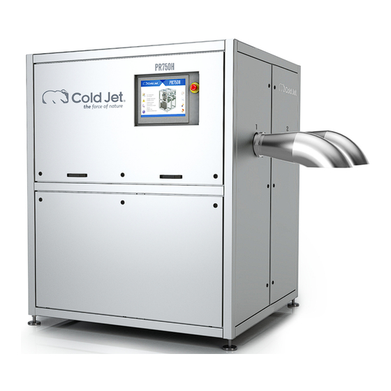
- Page 1 PR750H Pelletizer USER MANUAL Original Instructions [English] 25-05-2023 Rev 5...
- Page 2 CONFIDENTIAL BETWEEN COLD JET AND THE CLIENT AND REMAINS THE EXCLUSIVE PROPERTY OF COLD JET. IF YOU FIND ANY PROBLEMS IN THE DOCUMENTATION, PLEASE REPORT THEM TO US IN WRITING. COLD JET DOES NOT WARRANT THAT THIS DOCUMENT IS ERROR-FREE.
-
Page 3: Table Of Contents
Hydraulic station: • Safety device replacement intervals • Terms of Warranty • Cleaning the PR750H • INSTRUCTION – UNPACKING AND PREPARATIONS BEFORE INSTALLATION End of life for the PR750H • Version: PR750H Page: 2 of 21 User manual Date: 2023.05.25... - Page 4 Version: PR750H Page: 3 of 21 User manual Date: 2023.05.25...
-
Page 5: Introduction
The machine parts are protected by a moisture-free enclosure, which also reduces the noise level to a minimum (below 75 dB(a). The PR750H provides a non-stop supply of high-density dry ice pellets. The source of raw material for the production of pellets is liquid carbon dioxide preserved at low temperatures in a storage tank. -
Page 6: System Description
=G01-G1-MO1 for the extruder piston will extract until plug set point is reached and the hydraulic cylinder will again retract. This cycle will continue until a different step is selected. During production, it is possible to set the PR750H on standby. -
Page 7: System Identification
System identification System is marked with: Supplier responsible for the equipment Cold Jet ApS Industrivej 68 DK-6740 Bramming Denmark Phone: +45 75 56 15 00 Fax: +45 75 56 15 09 Homepage: www.coldjet.com Version: PR750H Page: 6 of 21 User manual Date: 2023.05.25... -
Page 8: Technical Data
1,7 – 3 – 6 – 10 – 16 inch: 0.07 – 0.12 – 0.24 - 0.39 - 0.62 Inlet Liquid CO Pressure: Liquid CO2 Supply System PR750H Supply Pressure (Min-Max) 13-18 bar (189-261 psi) Supply Pressure Range +/- 1.0 bar (14.5 psi) -
Page 9: Safety Regulations
The owner of the machine shall make sure that the operator, who is to work with the PR750H, fully understands the importance of studying the contents of this manual and comply with the SAFETY REGULATIONS described on the following pages as well as those placed on the machine. -
Page 10: Danger Of Suffocation
It is recommended to use a plastic shovel in the dry ice container. Version: PR750H Page: 9 of 21 User manual Date: 2023.05.25... -
Page 11: Danger Of Congelation
While working with the conveyor system, the operator must wear protective gloves to avoid contact with the dry ice or with parts of the machine which are in direct contact with the dry ice. Version: PR750H Page: 10 of 21... -
Page 12: Safety Operation
SAFETY OPERATION Emergency stop All equipment is connected to the general emergency system for PR750H. When an emergency-stop device is activated, all components located in the emergency zone will be disconnected from their power source. Machine safety There are machine safety measures in the following areas: Extruder unit •... -
Page 13: Machine Structure
MACHINE STRUCTURE PR750H 1 Pellet outlet sprout 2 Hydraulic station 3 Main hydraulic cylinder 4 Touch panel 5 Extruder plate cylinder 6 Extruder plate changer 7 Connection to an external supply, CO in and Out Version: PR750H Page: 12 of 21... -
Page 14: Machine Controls
MACHINE CONTROLS The PR750H is controlled from an HMI screen. The next section will describe the function of the HMI. PR750H HMI Screen 1. Homepage 2. Start, stop, and pause 3. Manuel/automatic 4. Process values 5. Alarm and history page 6. - Page 15 Activating standby mode the PR750H will go into a pause mode. When the PR750H is in a standby mode, the HMI screen changes the start buttons color to yellow. If the pause time exceeds the set pre-entered set point, the machine will automatically run a stop cycle and re- enter operation mode after the cycle is done.
- Page 16 For more information please see the appendix Alarm list The History page shows the last 1000 alarms of the PR750H. 6 Password protection Some functions are password protected. To change these values the User must log in.
- Page 17 Info page divided into 2 pages, PG1 and PG2. PG1 is the Production log, and it has the last 1000 productions. PG 2 shows information such as Device, PLC, Software, and TeamViewer ID. Version: PR750H Page: 16 of 21 User manual Date: 2023.05.25...
-
Page 18: User Level Hmi Screen
User Level HMI Screen. This section will describe the extra options when the machine is logged in on User Level. 11. Set Point Values 12. Manual Mode Version: PR750H Page: 17 of 21 User manual Date: 2023.05.25... - Page 19 Most components have names like “purge valve” and moving the hydraulic cylinders can be done by starting the hydraulic motor and pressing the arrow buttons. The hydraulic valves have numbers corresponding to the P&I diagram. Version: PR750H Page: 18 of 21 User manual Date: 2023.05.25...
-
Page 20: Repair And Warranty
Get a particle analysis of the oil if in doubt about the contamination degree. Cold Jet recommends that the owner has a spare parts package in stock, so repairs can be made quickly and with little loss of production time. -
Page 21: Terms Of Warranty
Protect all electronic equipment. All surfaces can be cleaned with a degreaser and acid-free oil. If the bottom of the PR750H is full of water/oil then there is a drain plug that can be found on the backside of the PR750H. -
Page 23: Instruction - Unpacking And Preparations Before Installation
INSTRUCTION – UNPACKING AND PREPARATIONS BEFORE INSTALLATION Your new PR750H has been assembled as one unit. In order to avoid damages during transport, the PR750H has been bolted onto the transport pallet. Unpacking and Examination for Transport Damages 1. Examine the transport box for any damages that may have occurred during transportation. - Page 24 Installation of the PR750H The installation of the PR750H must be carried out by a Cold Jet service technician, or by a technician approved by Cold Jet.
-
Page 25: End Of Life For The Pr750H
Disconnect the power Disconnect the CO Drain the PR750 oil For handing of the PR750H read section INSTRUCTION – UNPACKING AND PREPARATIONS BEFORE INSTALLATION. The materials and oil must be disposed of according to the jurisdictional rules and regulations for proper disposal. - Page 27 Technical File PR750H Table for mechanical maintenance Alarm list P&I Diagram Assembly drawings Installation layout drawings Wiring diagram...
- Page 29 Technical File PR750H Table for mechanical maintenance...
- Page 30 CONFIDENTIAL BETWEEN COLD JET AND THE CLIENT AND REMAINS THE EXCLUSIVE PROPERTY OF COLD JET. IF YOU FIND ANY PROBLEMS IN THE DOCUMENTATION, PLEASE REPORT THEM TO US IN WRITING. COLD JET DOES NOT WARRANT THAT THIS DOCUMENT IS ERROR-FREE.
- Page 31 Get a particle analysis of the oil if in doubt about the contamination degree. Cold Jet recommend the owner to have a spare part package in stock, so repairs can be made quickly and with a very little loss of production time.
- Page 32 This table includes all the service intervals from 0 hours to 20000 hours. For each service interval there will be listed which procedures is necessary to perform and the Cold Jet article no. for spare parts package. Table 1. Table for mechanical maintenance Pelletizer PR750H Service interval Hours/Month Procedure no.
- Page 33 After locating procedure numbers in the table for service interval, you have to find the procedure numbers in the table below which will lead to detailed procedures on pages in the appendix. Contents PROCEDURES FOR MAINTENANCE AND REPAIR ...................... 3 PR750H PR350H .............. 4 ROCEDURE FOR CHANGING FILTER AND GASKET ON AND ...
-
Page 34: Procedure For Changing Co 2 Filter And Gasket On
1. Procedure for changing CO filter and gasket on PR750H and PR350H During this operation it’s This section will describe how to changing CO filter and gasket on PR750H and PR350H. important to activate the emergency stop button! Disassembling the CO2 filter housing Remove the filter housing by loosening the 4 screws [1] and pull the filter housing end plate [2], gasket [3], filter [4] out wards. - Page 35 Compound on all bolts. The bolts need to be tightened see Procedure for changing the extruder piston on PR750H and PR350H During this operation it’s important This section will describe changing the extruder piston on PR750H and PR350H. to activate the emergency stop button. Disassembling the extruder plate changer Remove one of the extruder plates [ 3 ] by loosening the 2 screws [ 4 ] and push out the extruder plate in the opposite direction.
- Page 36 Drive the piston forward approx. 200MM in manual mode, see instructions regarding operation in manual mode below. Loosen the 8 screws [11] and remove screws, washers [12] and brackets [10] for piston. The piston [13] can now be driven out through the front of the barrel. PR750H Version: Page:...
- Page 37 PR750H Version: Page: 7 of 69 MECHANICAL MAINTENANCE Date: 2020.12.11...
- Page 38 Rest the machine, , but I manual mode. Login in with the user code. Table 3. User and pass word for PR750H User name Pass word User ColdjetPR2020 Go to manual mode, start the hydraulic pump and move the piston.
- Page 39 After completion, check the extruder unit for leaks. PR750H Version: Page: 9 of 69 MECHANICAL MAINTENANCE Date: 2020.12.11...
-
Page 40: And Pr350H
Procedure for changing the air filter on PR750H and PR350H During this operation it’s important to This section will describe changing the air filter on PR750H and PR350H. activate the emergency stop button. Unscrew the air filter unit pos. 1 from plug holes pos. 4 in hydraulic station. Unscrew the yellow air filter pos. 2. - Page 41 Procedure for changing hydraulic pump or repair on PR750H and PR350H This operation is only to be carried out by Cold Jet service technician or by an Cold Jet approved company such as Parker. The owner’s qualified personnel who have been trained by Cold Jet in the repair and maintenance of Cold Jet dry ice production machines and accessories can in special repair cases such as this be allowed by Cold Jet to carry out this repair procedure.
- Page 42 5. Procedure for changing oil on hydraulic station on PR750H and PR350H During this operation it’s This section will describe changing oil on hydraulic station on PR750H and PR350H. important to activate the emergency stop button. Remove the oil. Drain out of this ball valve pos. 1. The used oil must be deposited at an approved station for environmental waste.
- Page 43 Torque table After assembling check the filter for leaks. PR750H Version: Page: 13 of 69 MECHANICAL MAINTENANCE Date: 2020.12.11...
-
Page 44: Procedure For Changing Degassing Filters On Pr750H And Pr350H
6. Procedure for changing degassing filters on PR750H and PR350H During this operation it’s This section will describe how to changing degassing filters on PR750H and PR350H. important to activate the emergency stop button! Disassembling the degassing sleeves Remove the filter housing by loosening the 8 screws [5] and pull the filter housing [1], rubber gasket [2], filter [3] and filter gasket [4] out wards. - Page 45 Assemble the degassing sleeves. Take the filter gasket [4], filter [3], rubber gasket [2] and the extruder unit. Clean the thread and apply Anti-Seize Food Grade Compound on all bolts. The bolts need to be tightened by see Procedure for changing the extruder piston on PR750H and PR350H During this operation it’s important This section will describe changing the extruder piston on PR750H and PR350H.
- Page 46 Drive the piston forward approx. 200MM in manual mode, see instructions regarding operation in manual mode below. Loosen the 8 screws [11] and remove screws, washers [12] and brackets [10] for piston. The piston [13] can now be driven out through the front of the barrel. PR750H Version: Page:...
- Page 47 Rest the machine, , but I manual mode. Login in with the user code. Table 3. User and pass word for PR750H User name Pass word User ColdjetPR2020 Go to manual mode, start the hydraulic pump and move the piston.
- Page 48 After completion, check the extruder unit for leaks. PR750H Version: Page: 18 of 69 MECHANICAL MAINTENANCE Date: 2020.12.11...
- Page 49 Procedure for changing the air filter on PR750H and PR350H During this operation it’s important to This section will describe changing the air filter on PR750H and PR350H. activate the emergency stop button. Unscrew the air filter unit pos. 1 from plug holes pos. 4 in hydraulic station. Unscrew the yellow air filter pos. 2.
- Page 50 Procedure for changing hydraulic pump or repair on PR750H and PR350H This operation is only to be carried out by Cold Jet service technician or by an Cold Jet approved company such as Parker. The owner’s qualified personnel who have been trained by Cold Jet in the repair and maintenance of Cold Jet dry ice production machines and accessories can in special repair cases such as this be allowed by Cold Jet to carry out this repair procedure.
- Page 51 10. Procedure for changing oil on hydraulic station on PR750H and PR350H During this operation it’s This section will describe changing oil on hydraulic station on PR750H and PR350H. important to activate the emergency stop button. Remove the oil. Drain out of this ball valve pos. 1. The used oil must be deposited at an approved station for environmental waste.
- Page 52 Torque table. The screws [5] are to be tightening equally, and not so tight that rubber gasket is broken. After assembling check the extruder unit for leaks. PR750H Version: Page: 22 of 69 MECHANICAL MAINTENANCE Date: 2020.12.11...
-
Page 53: Procedure For Changing The Extruder Piston Front Part On Pr750H And Pr350H
11. Procedure for changing the Extruder Piston front part on PR750H and PR350H During this operation it’s important This section will describe how to changing piston ring on PR750H and PR350H. to activate the emergency stop button! Disassembling the extruder plate changer Remove one of the extruder plates [3] by loosening the 2 screws [4] and push out the extruder plate in the opposite direction. - Page 54 Drive the piston forward approx. 200MM in manual mode, see instructions regarding operation in manual mode below. Loosen the 8 screws [11] and remove screws, washers [12] and brackets [10] for piston. The piston [13] can now be driven out through the front of the barrel. PR750H Version: Page:...
- Page 55 Rest the machine, , but I manual mode. Login in with the user code. Table 2. User and pass word for PR750H User name Pass word User ColdjetPR2020 Go to manual mode, start the hydraulic pump and move the piston.
-
Page 56: Procedure For Changing Hydraulic Return Oil Filter On Pr750H And Pr350H
12. Procedure for changing hydraulic return oil filter on PR750H and PR350H During this operation it’s This section will describe how to changing hydraulic return oil filter on PR750H and PR350H. important to activate the emergency stop button! Disassembling hydraulic return oil filter Remove the filter housing by loosening the 4 screws [1] and pull the filter housing top plate [2], gasket, filter [4] out wards. - Page 57 Drive the piston forward approx. 200MM in manual mode, see instructions regarding operation in manual mode below. Loosen the 8 screws [11] and remove screws, washers [12] and brackets [10] for piston. The piston [13] can now be driven out through the front of the barrel. PR750H Version: Page:...
- Page 58 PR750H Version: Page: 28 of 69 MECHANICAL MAINTENANCE Date: 2020.12.11...
- Page 59 Rest the machine, , but I manual mode. Login in with the user code. Table 3. User and pass word for PR750H User name Pass word User ColdjetPR2020 Go to manual mode, start the hydraulic pump and move the piston.
- Page 60 After completion, check the extruder unit for leaks. PR750H Version: Page: 30 of 69 MECHANICAL MAINTENANCE Date: 2020.12.11...
- Page 61 Procedure for changing the air filter on PR750H and PR350H During this operation it’s important to This section will describe changing the air filter on PR750H and PR350H. activate the emergency stop button. Unscrew the air filter unit pos. 1 from plug holes pos. 4 in hydraulic station. Unscrew the yellow air filter pos. 2.
- Page 62 Procedure for changing hydraulic pump or repair on PR750H and PR350H This operation is only to be carried out by Cold Jet service technician or by an Cold Jet approved company such as Parker. The owner’s qualified personnel who have been trained by Cold Jet in the repair and maintenance of Cold Jet dry ice production machines and accessories can in special repair cases such as this be allowed by Cold Jet to carry out this repair procedure.
- Page 63 16. Procedure for changing oil on hydraulic station on PR750H and PR350H During this operation it’s This section will describe changing oil on hydraulic station on PR750H and PR350H. important to activate the emergency stop button. Remove the oil. Drain out of this ball valve pos. 1. The used oil must be deposited at an approved station for environmental waste.
- Page 64 Torque table After completion check the filter for leaks by go in to manual mode and move the pistons forwards and backwards. The user has to login for this operation. Hydraulic pump Manual mode Pistol PR750H Version: Page: 34 of 69 MECHANICAL MAINTENANCE Date: 2020.12.11...
-
Page 65: Procedure For Changing Gaskets In Hydraulic Cylinders On Pr750H And Pr350H
17. Procedure for changing gaskets in hydraulic cylinders on PR750H and PR350H During this This section will describe how to changing gaskets in hydraulic cylinders on PR750H and PR350H. operation it’s important to activate the emergency stop button and disconnected the hydraulic cylinder from the hydraulic system. - Page 66 Hydraulic pump Manual mode Pistol After completion, check the extruder unit for leaks. PR750H Version: Page: 36 of 69 MECHANICAL MAINTENANCE Date: 2020.12.11...
-
Page 67: Procedure For Changing The Wear Inserts In Die Changer On Pr750H And Pr350H
18. Procedure for changing the wear inserts in die changer on PR750H and PR350H During this This section will describe how to changing the wear inserts in die changer on PR750H and PR350H. operation it’s important to activate the emergency stop button. - Page 68 Tightening and loosening procedure for super bolt PR750H Version: Page: 38 of 69 MECHANICAL MAINTENANCE Date: 2020.12.11...
-
Page 69: Procedure For Changing The Hydraulic Cylinder On Pr750H And Pr350H
19. Procedure for changing the hydraulic cylinder on PR750H and PR350H During this operation it’s This section will describe how to changing the hydraulic cylinder on PR750H and PR350H. important to activate the emergency stop button. Disassembling the extruder plate changer Remove one of the extruder plates [3] by loosening the 2 screws [4] and push out the extruder plate in the opposite direction. - Page 70 Drive the piston forward approx. 200MM in manual mode, see instructions regarding operation in manual mode below. Loosen the 8 screws [11] and remove screws, washers [12] and brackets [10] for piston. The piston [13] can now be driven out through the front of the barrel. PR750H Version: Page:...
- Page 71 Remove the nuts [ 16 ] and the spacers [ 17 ] one at a time. A spring loaded gasket [ 18 ] is located between the hydraulic cylinder and the center plate. This should be removed before the cylinder is lifted out of the machine. PR750H Version:...
- Page 72 Assemble the hydraulic cylinder, going backwards in the procedure steps. After completion check for leaks and degassing sleeves are tightened correctly. PR750H Version: Page: 42 of 69...
-
Page 73: Procedure For Changing The Hydraulic Cylinder Ø50 On Pr750H And Pr350H
20. Procedure for changing the hydraulic cylinder Ø50 on PR750H and PR350H During this operation This section will describe how to changing the hydraulic cylinder Ø50 on PR750H and PR350H. it’s important to activate the emergency stop button. Disassembling the hydraulic cylinder Ø50 Disconnect the plug for Transducer and the hydraulic hoses, plug both hose connection and connections on the hydraulic cylinder, be very careful and protect the Transducer connection against any damage. - Page 74 Remove the filter on one side of the extruder cylinder to gain access to the piston by loosening the 8 screws [9] and pull the filter housing [5], rubber gasket [6], filter [7] and filter gasket [8] out, and you have access inside the extruder chamber. PR750H Version: Page:...
- Page 75 Drive the piston forward approx. 200MM in manual mode, see instructions regarding operation in manual mode below. Loosen the 8 screws [11] and remove screws, washers [12] and brackets [10] for piston. The piston [13] can now be driven out through the front of the barrel. PR750H Version: Page:...
- Page 76 Rest the machine, , but I manual mode. Login in with the user code. Table 3. User and pass word for PR750H User name Pass word User ColdjetPR2020 Go to manual mode, start the hydraulic pump and move the piston.
- Page 77 After completion, check the extruder unit for leaks. PR750H Version: Page: 47 of 69 MECHANICAL MAINTENANCE Date: 2020.12.11...
- Page 78 Procedure for changing the air filter on PR750H and PR350H During this operation it’s important to This section will describe changing the air filter on PR750H and PR350H. activate the emergency stop button. Unscrew the air filter unit pos. 1 from plug holes pos. 4 in hydraulic station. Unscrew the yellow air filter pos. 2.
- Page 79 Procedure for changing hydraulic pump or repair on PR750H and PR350H This operation is only to be carried out by Cold Jet service technician or by an Cold Jet approved company such as Parker. The owner’s qualified personnel who have been trained by Cold Jet in the repair and maintenance of Cold Jet dry ice production machines and accessories can in special repair cases such as this be allowed by Cold Jet to carry out this repair procedure.
- Page 80 24. Procedure for changing oil on hydraulic station on PR750H and PR350H During this operation it’s This section will describe changing oil on hydraulic station on PR750H and PR350H. important to activate the emergency stop button. Remove the oil. Drain out of this ball valve pos. 1. The used oil must be deposited at an approved station for environmental waste.
- Page 81 Torque table. After completion please check in manual mode that the cylinder is working and there are non-leaks. PR750H Version: Page: 51 of 69 MECHANICAL MAINTENANCE Date: 2020.12.11...
-
Page 82: Procedure For Changing Danfoss Ev3 And Solenoids On Pr750H And Pr350H
[ 3 ] , remove the EV15 valve [4] . Replace the EV15 valve and solenoid if [ 1, 3 ] are to be tightened see Procedure for changing the extruder piston on PR750H and PR350H During this operation it’s important... - Page 83 Drive the piston forward approx. 200MM in manual mode, see instructions regarding operation in manual mode below. Loosen the 8 screws [11] and remove screws, washers [12] and brackets [10] for piston. The piston [13] can now be driven out through the front of the barrel. PR750H Version: Page:...
- Page 84 PR750H Version: Page: 54 of 69 MECHANICAL MAINTENANCE Date: 2020.12.11...
- Page 85 Rest the machine, , but I manual mode. Login in with the user code. Table 3. User and pass word for PR750H User name Pass word User ColdjetPR2020 Go to manual mode, start the hydraulic pump and move the piston.
- Page 86 After completion, check the extruder unit for leaks. PR750H Version: Page: 56 of 69 MECHANICAL MAINTENANCE Date: 2020.12.11...
-
Page 87: And Pr350H
Procedure for changing the air filter on PR750H and PR350H During this operation it’s important to This section will describe changing the air filter on PR750H and PR350H. activate the emergency stop button. Unscrew the air filter unit pos. 1 from plug holes pos. 4 in hydraulic station. Unscrew the yellow air filter pos. 2. -
Page 88: Procedure For Changing Hydraulic Pump Or Repair On Pr750H And Pr350H
Procedure for changing hydraulic pump or repair on PR750H and PR350H This operation is only to be carried out by Cold Jet service technician or by an Cold Jet approved company such as Parker. The owner’s qualified personnel who have been trained by Cold Jet in the repair and maintenance of Cold Jet dry ice production machines and accessories can in special repair cases such as this be allowed by Cold Jet to carry out this repair procedure. -
Page 89: Procedure For Changing Oil On Hydraulic Station On Pr750H And Pr350H
29. Procedure for changing oil on hydraulic station on PR750H and PR350H During this operation it’s This section will describe changing oil on hydraulic station on PR750H and PR350H. important to activate the emergency stop button. Remove the oil. Drain out of this ball valve pos. 1. The used oil must be deposited at an approved station for environmental waste. - Page 90 Torque table Check that there are no leaks by the connections. Notice! It is very important to be careful and not get any dust or dirt into the valve or pipes under this operation; this could block the Danfoss solenoid valves PR750H Version: Page:...
- Page 91 Procedure for changing the extruder piston on PR750H and PR350H During this operation it’s important This section will describe changing the extruder piston on PR750H and PR350H. to activate the emergency stop button. Disassembling the extruder plate changer Remove one of the extruder plates [ 3 ] by loosening the 2 screws [ 4 ] and push out the extruder plate in the opposite direction.
- Page 92 Drive the piston forward approx. 200MM in manual mode, see instructions regarding operation in manual mode below. Loosen the 8 screws [11] and remove screws, washers [12] and brackets [10] for piston. The piston [13] can now be driven out through the front of the barrel. PR750H Version: Page:...
- Page 93 Rest the machine, , but I manual mode. Login in with the user code. Table 3. User and pass word for PR750H User name Pass word User ColdjetPR2020 Go to manual mode, start the hydraulic pump and move the piston.
- Page 94 Hydraulic pump Manual mode Pistol After completion, check the extruder unit for leaks. PR750H Version: Page: 64 of 69 MECHANICAL MAINTENANCE Date: 2020.12.11...
- Page 95 Procedure for changing the air filter on PR750H and PR350H During this operation it’s important to This section will describe changing the air filter on PR750H and PR350H. activate the emergency stop button. Unscrew the air filter unit pos. 1 from plug holes pos. 4 in hydraulic station. Unscrew the yellow air filter pos. 2.
- Page 96 Procedure for changing hydraulic pump or repair on PR750H and PR350H This operation is only to be carried out by Cold Jet service technician or by an Cold Jet approved company such as Parker. The owner’s qualified personnel who have been trained by Cold Jet in the repair and maintenance of Cold Jet dry ice production machines and accessories can in special repair cases such as this be allowed by Cold Jet to carry out this repair procedure.
- Page 97 33. Procedure for changing oil on hydraulic station on PR750H and PR350H During this operation it’s This section will describe changing oil on hydraulic station on PR750H and PR350H. important to activate the emergency stop button. Remove the oil. Drain out of this ball valve pos. 1. The used oil must be deposited at an approved station for environmental waste.
-
Page 98: Torque Table
This section will describe Torque for tightening different sizes and types of fasteners. If the fasteners are tightened without thread locking agent, it is recommended to apply an anti-seize food grade lubricant. If the bolts are tightened with a thread locking agent, the threads must be considered as lubricated. PR750H Version: Page:... - Page 99 Technical File PR750H Alarm list...
- Page 101 CONFIDENTIAL BETWEEN COLD JET AND THE CLIENT AND REMAINS THE EXCLUSIVE PROPERTY OF COLD JET. IF YOU FIND ANY PROBLEMS IN THE DOCUMENTATION, PLEASE REPORT THEM TO US IN WRITING. COLD JET DOES NOT WARRANT THAT THIS DOCUMENT IS ERROR-FREE.
- Page 102 ALARM LIST Using the alarm list and diagrams in the appendix for solving problems with the Pelletizer PR750H/350H. When errors appear comparing and indentify it in the table below. Then go to the appendix at the page which is listed in the table.
- Page 103 Troubleshooting errors on Pelletizer PR750H and PR350H. • Solving alarm tag name ID 1 FB_G0x.Max_PurgeTime - Max. Purge time Check if the valve is frozen. => tough up the valve. Yes, one of the valves Reset and restart Check the valve for mechanical failure. => replace the valve.
- Page 104 Troubleshooting errors on Pelletizer PR750H and PR350H. Solving alarm ID 2 tag name FB_MOx.MaxTime_FWD - Max. time forwards 1. There could be a mechanical problem inside the extruder cylinder or hydraulic Yes, there is a mechanical problem or Repair or replace the component Reset and restart cylinder.
- Page 105 Troubleshooting errors on Pelletizer PR750H and PR350H. • Solving alarm tag name ID 3 FB_TwinSAFE_Estop.Emergency_Stop - Emergency stop activated. Yes, the emergency stop button is Reset and restart Release emergency stop button. activated. the Pelletizer. 1. Check if the emergency stop button is activated.
- Page 106 Troubleshooting errors on Pelletizer PR750H and PR350H. • Solving alarm tag name ID nr 4 FB_MOx.MaxTime_RWD ‐ Max. time return 1. There could be a build up of dry ice inside the extruder cylinder behind the Yes, the piston ring or piston is worn Replace the component which are Reset and restart extruder piston. or damaged. broken or worn out. the Pelletizer. Tag name ID nr 4 Remove the degassing boxes and filters. FB_MOx.MaxTime_RWD In "Single mode" drive the piston forward Max. time return until the pistonring appears. Check the piston ring and piston for No, there is no problems. Contact Cold Jet technical support. mechanical wear. ...
- Page 107 Troubleshooting errors on Pelletizer PR750H and PR350H. • Solving alarm tag name ID 5+6+7+8+9+10+11+12+13+14+15+16+17+18+19+20 internal error. Yes, the error is still there Contact Cold Jet for tecnical support. Tag name ID 1. There is an internal error in the system. 5+6+7+8+9+10+11+12+13+14+15+1 Try to reset and restart the system 6+17+18+19+20 internal error. No, there is no error anymore. Continue production. ...
- Page 108 Troubleshooting errors on Pelletizer PR750H and PR350H. • Solving alarm tag name ID 21 P_Machine.fbHU01.fbTT1.foSP ‐ Max. oil temp. 1. The temperature of the hydraulic oil is to Refill with the necesarry amount of Reset and restart Yes, the oil level is low. high above 70°C (158°F). oil. the Pelletizer. The error cannot be reset until the temperature has fallen below 50°C (122°F). Check oil level. No, there is no problems. Go to point 2 2. The temperature of the hydraulic oil is Yes, the oil quality is not Change the hydraulic oil according to Reset and restart to high above 70°C (158°F). satisfiying. It is contaminated. procedure no. 13 the Pelletizer. Tag name ID 21 The error cannot be reset until the P_Machine.fbHU01.fbTT1.foSP temperature has fallen below 50°C ‐ Max. oil temp.. (122°F). No, there is no problem. Go to point 3 Check oil quality. 3. The temperature of the hydraulic oil is Replace the transmitter Yes, the oil temperature Reset and restart to high above 70°C (158°F). or repair the wire ...
- Page 109 Troubleshooting errors on Pelletizer PR750H and PR350H. • Solving alarm tag name ID 22 P_Machine.fbHU01.fbC1_BL1 ‐ Oil level too low / level sensor activated. Refill with the necesarry amount of Reset and restart Yes, the oil level is low. oil. the Pelletizer. 1. The level sensor is activated. Check oil level. No, there is no problems. Go to point 2 Yes, the oil quality is Change the hydraulic oil according to Reset and restart not satisfiying. It is procedure no. 13 the Pelletizer. contaminated. Tag name ID 22 2. The level sensor is activated. P_Machine.fbHU01.fbC1_BL1 Oil level too low / level sensor Check oil quality. activated. No, there is no Go to point 3 problem. Yes, the oil temperature Replace the sensor or Reset and restart transmitter is not working or repair the wire the Pelletizer. connections are instable. connections. 3. The level sensor is activated. Check oil level sensor and wire ...
- Page 110 Troubleshooting errors on Pelletizer PR750H and PR350H. • Solving alarm tag name ID 23 FB_W01.Low_Temperature_TT3 ‐ Low temperature TT3 1. There could be CO particles in the Yes, the degassing filter is worn, Replace the component which are Reset and restart degassing sytem. blocked or damaged. broken or worn out. the Pelletizer. Remove the degassing boxes and filters. Check the degassing filters for wear or damage. No, there is no problems. Go to point 2 Tag name ID 23 FB_W01.Low_Temperature_TT 3 ‐ Low temperature TT3 Yes, the transmitter is damaged or Replace transmitter or repair the Reset and restart wire connctions are instable. wire connections. the Pelletizer. 2. There could be CO particles in the degassing sytem. Check the temperature transmitter and its wire connections. No, there is no problems Contact Cold Jet technical support.
- Page 111 Troubleshooting errors on Pelletizer PR750H and PR350H. • Solving alarm tag name ID 24 FB_W01.Low_CO2_Pressure_TP1 ‐ Low CO2 pressure Check if the valve is frozen. => tough up the valve. Yes, one of the valves are Check the valve for mechanical failure. => Reset and restart not working replace the valve. the Pelletizer. Check the valve for electrical failure.=> find failure and repair. 1. Check the functioning of the valves W01‐ Q1‐K1 / W01‐Q2‐K2 in “Single mode”. No, both valves are working Go to point 2 Yes, a valve is not in Reset and restart 2. Check that manual valves are in the Set the valve to the correct position. the correct position. the Pelletizer. Tag name ID 24 correct positions. FB_W01.Low_CO2_Pressure_T CO2 gas valves is closed. P1 ‐ Low CO2 pressure No, all valves is in the CO2 liquid valves is open. Go to point 3 correct position. Reset and restart the ...
- Page 112 Troubleshooting errors on Pelletizer PR750H and PR350H. • Solving alarm tag name ID 25 FB_G0x.General_TimeOut - General TimeOut Yes, the error is still there Contact Cold Jet for tecnical support. Tag name ID 25 FB_G0x.General_TimeOut - General Try to reset and restart the system TimeOut No, there is no error anymore.
- Page 113 Troubleshooting errors on Pelletizer PR750H and PR350H. • Solving alarm tag name ID 26 FB_G0x.Build_Pillow ‐ Build pillow Reset and restart 1. This could be due to pressure drop in the Yes, the tank is empty. Fill the tank. the Pelletizer. CO2 installation. Check that there is sufficient CO2 in the tank. No, the tank is full. Go to point 2 2. This could be due to pressure drop in Yes, a valve is not in the correct Reset and restart the CO2 installation. Set the valve to the correct position. position.. the Pelletizer. Tag name ID 26 Check that manual valves are in the FB_G0x.Build_Pillow ‐ Build correct pillow positions. No, all valves is in the correct Contact Cold Jet CO2 gas valves is closed. position. technical support. CO2 liquid valves is open. Reset and restart 3. This could be due to pressure drop in Yes, the filter is blocked or dirty. Replace the filter or clean it. the Pelletizer. CO2 installation.
- Page 114 Troubleshooting errors on Pelletizer PR750H and PR350H. • Solving alarm tag name ID 27 FB_G0x.Min_Pillow_Size ‐ Min. Pillow Size Reset and restart 1. This could be due to pressure drop in the Yes, the tank is empty. Fill the tank. the Pelletizer. CO2 installation. Check that there is sufficient CO2 in the tank. No, the tank is full. Go to point 2 2. This could be due to pressure drop in Yes, a valve is not in the correct Reset and restart the CO2 installation. Set the valve to the correct position. position.. the Pelletizer. Tag name ID 27 Check that manual valves are in the FB_G0x.Min_Pillow_Size ‐ Min. correct Pillow Size positions. No, all valves is in the correct Contact Cold Jet CO2 gas valves is closed. position. technical support. CO2 liquid valves is open. Reset and restart 3. This could be due to pressure drop in Yes, the filter is blocked or dirty. Replace the filter or clean it. the Pelletizer. CO2 installation.
- Page 115 Troubleshooting errors on Pelletizer PR750H and PR350H. • Solving alarm tag name ID 28 FB_G0x.Max_Pillow_Size ‐ Max. Pillow Size Reset and restart 1. This could be due to pressure drop in the Yes, the tank is empty. Fill the tank. the Pelletizer. CO2 installation. Check that there is sufficient CO2 in the tank. No, the tank is full. Go to point 2 2. This could be due to pressure drop in Yes, a valve is not in the correct Reset and restart the CO2 installation. Set the valve to the correct position. position.. the Pelletizer. Tag name ID 28 Check that manual valves are in the FB_G0x.Max_Pillow_Size ‐ Max. correct Pillow Size positions. No, all valves is in the correct Contact Cold Jet CO2 gas valves is closed. position. technical support. CO2 liquid valves is open. Reset and restart 3. This could be due to pressure drop in Yes, the filter is blocked or dirty. Replace the filter or clean it. the Pelletizer. CO2 installation.
- Page 117 Technical File PR750H P&I Diagram...
- Page 119 =W04 (option) -G1-M1 -E1-M1 300L 300L Projection: Format: Sheet no: Description: Coldjet Aps Creator: Industrivej 68 P&I-Diagram For PR750H Date: DK-6740 Bramming 07-01-2021 REVISIONS REVISIONS TLF. +45 76561500 CE/UL 3x220-400V AC 50 Hz, 3x220-480V AC 60 Hz www.Coldjet.com Material: Scale: Weight: Drawing no.:...
- Page 120 1/11/2021 Tag-numbers for 2A0510 and 2A0511 UL/CE REV A COLDJET PART NUMBER ASPECT ASPECT DESCRIPTION TAG DESCRIPTION DESCRIPTION Digital I/O Analog I/O Comments Dry ice processing unit DI=V01 Filter unit (Option) DI=V01 Filter unit (Option) Filter for filter unit DI=V01 Filter unit (Option) Man.
- Page 121 1/11/2021 Tag-numbers for 2A0510 and 2A0511 UL/CE REV A DI=HU01 Hydraulic unit for pellet extruder -Q12 Restrictor valve for hydraulic unit DI=HU01 Hydraulic unit for pellet extruder -Q13 Restrictor valve for hydraulic unit DI=HU01 Hydraulic unit for pellet extruder -Q15 Valve for hydraulic drain DI=HU01 Hydraulic unit for pellet extruder...
- Page 123 Technical File PR750H Assembly drawings...
- Page 125 DESCRIPTION: THE DESIGN CONTAINED IN THIS DRAWING WAS ORIGINATED BY, AND IS THE EXCLUSIVE PROPERTY OF COLD JET, LLC. IT IS NOT TO BE PELLETIZER UNIT, PR750H UL/CE, 380-480 V USED IN ANY WAY DETRIMENTAL TO THE INTERESTS OF COLD JET, LLC.
- Page 126 DESCRIPTION: THE DESIGN CONTAINED IN THIS DRAWING WAS ORIGINATED BY, AND IS THE EXCLUSIVE PROPERTY OF COLD JET, LLC. IT IS NOT TO BE PELLETIZER UNIT, PR750H UL/CE, 220 V USED IN ANY WAY DETRIMENTAL TO THE INTERESTS OF COLD JET, LLC.
- Page 127 DESCRIPTION: THE DESIGN CONTAINED IN THIS DRAWING WAS ORIGINATED BY, AND IS THE EXCLUSIVE PROPERTY OF COLD JET, LLC. IT IS NOT TO BE PELLETIZER UNIT, PR750H UL/CE, 380-480 V USED IN ANY WAY DETRIMENTAL TO THE INTERESTS OF COLD JET, LLC.
- Page 128 THE DESIGN CONTAINED IN THIS DRAWING WAS ORIGINATED BY, AND IS THE EXCLUSIVE HYDRAULIC POWERPACK, PR750H, W/ADJUSTABLE FLOW PROPERTY OF COLD JET, LLC. IT IS NOT TO BE USED IN ANY WAY DETRIMENTAL TO THE INTERESTS OF COLD JET, LLC.
- Page 129 THE DESIGN CONTAINED IN THIS DRAWING WAS ORIGINATED BY, AND IS THE EXCLUSIVE HYDRAULIC POWERPACK, PR750H, W/ADJUSTABLE FLOW PROPERTY OF COLD JET, LLC. IT IS NOT TO BE USED IN ANY WAY DETRIMENTAL TO THE INTERESTS OF COLD JET, LLC.
- Page 130 THE DESIGN CONTAINED IN THIS DRAWING WAS ORIGINATED BY, AND IS THE EXCLUSIVE HOSE, HYDRAULIC, COMPLETE, PR750H PROPERTY OF COLD JET, LLC. IT IS NOT TO BE USED IN ANY WAY DETRIMENTAL TO THE INTERESTS OF COLD JET, LLC. MATERIAL:...
- Page 131 DESCRIPTION: THE DESIGN CONTAINED IN THIS DRAWING WAS ORIGINATED BY, AND IS THE EXCLUSIVE PROPERTY OF COLD JET, LLC. IT IS NOT TO BE FRAME, COMPLETE, PR750H, V5 USED IN ANY WAY DETRIMENTAL TO THE APPLY ANTI-SEIZE FOOD GRADE COMPOUND AFTER CLEANING THE THREADS.
- Page 132 DESCRIPTION: THE DESIGN CONTAINED IN THIS DRAWING WAS ORIGINATED BY, AND IS THE EXCLUSIVE PROPERTY OF COLD JET, LLC. IT IS NOT TO BE FRAME, COMPLETE, PR750H, V5 USED IN ANY WAY DETRIMENTAL TO THE INTERESTS OF COLD JET, LLC.
- Page 133 THE DESIGN CONTAINED IN THIS DRAWING WAS ORIGINATED BY, AND IS THE EXCLUSIVE EXTRUDER UNIT, COMPLETE, PR350H/PR750H V5 COMPOUND AFTER CLEANING THE PROPERTY OF COLD JET, LLC. IT IS NOT TO BE USED IN ANY WAY DETRIMENTAL TO THE THREADS INTERESTS OF COLD JET, LLC.
- Page 134 THE DESIGN CONTAINED IN THIS DRAWING may be needed WAS ORIGINATED BY, AND IS THE EXCLUSIVE EXTRUDER UNIT, COMPLETE, PR350H/PR750H V5 PROPERTY OF COLD JET, LLC. IT IS NOT TO BE USED IN ANY WAY DETRIMENTAL TO THE INTERESTS OF COLD JET, LLC. MATERIAL:...
- Page 135 THE DESIGN CONTAINED IN THIS DRAWING WAS ORIGINATED BY, AND IS THE EXCLUSIVE EXTRUDERCYLINDER, KOMPLET, PR350H/750H PROPERTY OF COLD JET, LLC. IT IS NOT TO BE BONDING FACES USED IN ANY WAY DETRIMENTAL TO THE INTERESTS OF COLD JET, LLC.
- Page 136 THE DESIGN CONTAINED IN THIS DRAWING WAS ORIGINATED BY, AND IS THE EXCLUSIVE CPL. BRACKET AND OUTLET SPROUT, PR350H/PR750H PROPERTY OF COLD JET, LLC. IT IS NOT TO BE USED IN ANY WAY DETRIMENTAL TO THE INTERESTS OF COLD JET, LLC.
- Page 137 THE DESIGN CONTAINED IN THIS DRAWING WAS ORIGINATED BY, AND IS THE EXCLUSIVE PISTON, EXTRUDER, COMPLETE, PR350H/PR750H APPLY ANTI-SEIZE FOOD GRADE COMPOUND PROPERTY OF COLD JET, LLC. IT IS NOT TO BE USED IN ANY WAY DETRIMENTAL TO THE INTERESTS OF COLD JET, LLC. MATERIAL:...
- Page 138 DESCRIPTION: THE DESIGN CONTAINED IN THIS DRAWING WAS ORIGINATED BY, AND IS THE EXCLUSIVE PROPERTY OF COLD JET, LLC. IT IS NOT TO BE Oil seal must turn with USED IN ANY WAY DETRIMENTAL TO THE CHANGER, DIE, PR350H/PR750H V5 INTERESTS OF COLD JET, LLC.
- Page 139 DESCRIPTION: THE DESIGN CONTAINED IN THIS DRAWING WAS ORIGINATED BY, AND IS THE EXCLUSIVE PROPERTY OF COLD JET, LLC. IT IS NOT TO BE TORQUE TO 65 FT-LBS (73,4 NM) USED IN ANY WAY DETRIMENTAL TO THE CO2 OUT, COMPLETE, PR750H INTERESTS OF COLD JET, LLC.
- Page 140 THE DESIGN CONTAINED IN THIS DRAWING WAS ORIGINATED BY, AND IS THE EXCLUSIVE APPLY ANTI-SEIZE FOOD GRADE COMPOUND PROPERTY OF COLD JET, LLC. IT IS NOT TO BE CO2 IN, 24VDC, PR750H USED IN ANY WAY DETRIMENTAL TO THE ON ALL BOLTS AND NUTS, AND FITTINGS INTERESTS OF COLD JET, LLC.
- Page 141 THE DESIGN CONTAINED IN THIS DRAWING WAS ORIGINATED BY, AND IS THE EXCLUSIVE BALLVALVE, 3/4", SINGLE PNEU. ACTUATOR AND COIL VALVE. PROPERTY OF COLD JET, LLC. IT IS NOT TO BE USED IN ANY WAY DETRIMENTAL TO THE INTERESTS OF COLD JET, LLC.
- Page 142 WAS ORIGINATED BY, AND IS THE EXCLUSIVE BALL VALVE, 1/2", 30° V-BALL, DOUBLE ACTING. PNEU. ACTUATOR AND COIL VA PROPERTY OF COLD JET, LLC. IT IS NOT TO BE USED IN ANY WAY DETRIMENTAL TO THE INTERESTS OF COLD JET, LLC.
- Page 143 THE DESIGN CONTAINED IN THIS DRAWING WAS ORIGINATED BY, AND IS THE EXCLUSIVE TEE DRAIN 1/2" COMPL. PROPERTY OF COLD JET, LLC. IT IS NOT TO BE USED IN ANY WAY DETRIMENTAL TO THE INTERESTS OF COLD JET, LLC. MATERIAL:...
- Page 144 NOTES: THE DESIGN CONTAINED IN THIS DRAWING WAS ORIGINATED BY, AND IS THE EXCLUSIVE PNEUMATIC UNIT PR750H PROPERTY OF COLD JET, LLC. IT IS NOT TO BE USED IN ANY WAY DETRIMENTAL TO THE INTERESTS OF COLD JET, LLC. MATERIAL:...
- Page 145 SIZE: DESCRIPTION: THE DESIGN CONTAINED IN THIS DRAWING WAS ORIGINATED BY, AND IS THE EXCLUSIVE PROPERTY OF COLD JET, LLC. IT IS NOT TO BE USED IN ANY WAY DETRIMENTAL TO THE CABLE COMPONENTS PR750H INTERESTS OF COLD JET, LLC.
- Page 146 THE DESIGN CONTAINED IN THIS DRAWING WAS ORIGINATED BY, AND IS THE EXCLUSIVE LED SIGNAL TOWER, KOMPAKT 37, WITH CABLE PROPERTY OF COLD JET, LLC. IT IS NOT TO BE USED IN ANY WAY DETRIMENTAL TO THE INTERESTS OF COLD JET, LLC.
- Page 147 Technical File PR750H Installation layout drawings...
- Page 149 Technical File PR750H Wiring diagram...
- Page 151 Technical data Projeckt title: Pelletizer Unit PR350-750H 2A0510 – 2A0512 Case number: Drawing number: 6G0564 REV A...
- Page 152 =DI/+A01 Page . Ref. designation Ref. description Page title Last modified Info =DI/+A01 Dryice Pelletizer, Main Control Panel Info 06-07-2020 07:52:14 =DI/+A01 Dryice Pelletizer, Main Control Panel Nameplate 27-07-2020 12:19:50 =DI/+A01 Dryice Pelletizer, Main Control Panel Fuse replacement 06-07-2020 07:52:14 =DI/+A01 Dryice Pelletizer, Main Control Panel Torque and settings information...
- Page 153 =DI/+A01 Page . Ref. designation Ref. description Page title Last modified =DI/+A01 Dryice Pelletizer, Main Control Panel PLC Hardware 18-08-2020 08:37:30 =DI/+A01 Dryice Pelletizer, Main Control Panel PLC Hardware 07-07-2020 11:16:12 =DI/+A01 Dryice Pelletizer, Main Control Panel PLC Hardware 18-08-2020 08:09:08 =DI/+A01 Dryice Pelletizer, Main Control Panel PLC Hardware...
- Page 154 =DI/+A01 Page . Ref. designation Ref. description Page title Last modified =DI/+A01 Dryice Pelletizer, Main Control Panel PLC Analog input 07-07-2020 08:50:16 PLC RTD Input PR350 =DI/+A01 Dryice Pelletizer, Main Control Panel PLC RTD Input PR350 07-07-2020 09:49:36 =DI/+A01 Dryice Pelletizer, Main Control Panel PLC RTD Input PR350 07-07-2020 11:47:02 Option Light Tower...
- Page 155 Page PI1 - PI7 Info...
- Page 156 =DI/+A01 Nameplate Holtec project No: Unique number for the cabinet If the production of several identical control unit occurs, then the project number must be followed by an underscore and a serial number. Eg. HE12010_001 Customer project No: Customers serial, type or project number FLA: Control panel Full Load Ampacity UL508A §...
- Page 157 =DI/+A01 Fuse replacement Fuse Replacement Marking Name: Type: Interrupt rating: Voltage: Place on the inside on the control panel door Project title: Pelletizer Unit PR350-750H Project no.: IT020044_001 Project rev.: Page Customer: Coldjet A/S DCC: Scale: Page title: Fuse replacement Dwg.
- Page 158 =DI/+A01 Torque and settings information Torque information mark Name: Torque: Setting: -F201 3,5-5A -F205 3,5-5A -Q11 6 Nm -Q402 21,7A -Q412 1,8-2,5A -Q422 1,8-2,5A -T201 2 Nm -T205 2 Nm Place on the inside on the control panel door Project title: Pelletizer Unit PR350-750H Project no.: IT020044_001...
- Page 159 =DI/+A01 Warning markings WARNING AVERTISSEMENT Maintenance on Industrial Control Panels shall only be performed by Les travaux de maintenance sur les panneaux de commande industriels ne trained, skilled and authorized electricians, using appropriate safe electrical peuvent être effectués que par des électriciens qualifiés, compétents et work practices including personal protective equipment, approved tools, agréés, en mettant en œuvre des pratiques de travail électrique sécuritaire procedures and accurate drawings of the panels involved.
- Page 160 =DI/+A01 Reference designations in the project All letter codes in reference designations are according to table 1 in the standard IEC/ISO 81346-2. Ref. designation Description Dryice Pelletizer +A01 Main Control Panel +A02 +A10 Combi350 Project title: Pelletizer Unit PR350-750H Project no.: IT020044_001 Project rev.: Page...
- Page 161 =DI/+A01 Wire identification UL508A Part 2 Industrial Machinery Colours DK Colours UK/US Abbreviation Internal Wire/Conductor Identification: Internal wire/conductors are identified by the terminal number, Sort Black off the component in which they are installed. Brun Brown Colour markings internal wires/conductors: Rød Wire/conductor colours used internally in the control panel in compliance with UL508A Sections 66.5 &...
- Page 162 =DI/+A01 Maintenancen Before operational use: Control Panel Preventive Maintenance: Before the control panel leave Holtec Automatic A/S workshop, it has been cleaned and tested, Preventive maintenance of the control panel, should take place at leats onde a year. according to Holtec standards, and in compliance with DS/EN 60204-1 When the preventive maintenance is performed, the checklist below can be used.
- Page 163 Page LAY1 - LAY2 Layout...
- Page 164 =DI/+A01 Project title: Pelletizer Unit PR350-750H Project no.: IT020044_001 Project rev.: Page LAY1 Customer: Coldjet A/S DCC: Scale: Page title: Layout Dwg. no.: Page rev.: Previous page: File name: IT020041_001 - PR350-750 - RevC Eng. (proj/page): Last print: 18-11-2020 Next page: LAY2 Page ref.: Dryice Pelletizer, Main Control Panel...
- Page 165 =DI/+A01 Project title: Pelletizer Unit PR350-750H Project no.: IT020044_001 Project rev.: Page LAY2 Customer: Coldjet A/S DCC: Scale: Page title: Layout Dwg. no.: Page rev.: Previous page: LAY1 File name: IT020041_001 - PR350-750 - RevC Eng. (proj/page): Last print: 18-11-2020 Next page: Page ref.: Dryice Pelletizer, Main Control Panel...
- Page 166 Page 1 - 1 Supply...
- Page 167 =DI/+A01 /20.0 /20.0 /20.0 /20.0 /20.0 -Q11 OT100F4N2 Main Disconnect PT 6-PE PT 6-PE 6 Nm -W11 PW Pelletizer Unit Project title: Pelletizer Unit PR350-750H Project no.: IT020044_001 Project rev.: Page Customer: Coldjet A/S DCC: Scale: Page title: Supply Dwg. no.: Page rev.: Previous page: LAY2...
- Page 168 Page 20 - 21 Power supply...
- Page 169 =DI/+A01 /1.9 /40.0 /1.9 /40.0 /1.9 /40.0 /1.9 /40.0 /1.9 /40.0 -F201 -F205 3,5-5A 3,5-5A 3RV2411-1FA20 3RV2411-1FA20 Hv C Lv Hv C Lv Hv C Lv Hv C Lv ABL8RPS24050 ABL8RPS24100 -T201 -T205 100V/200-500VAC/ 100V/200-500VAC/ 24VDC 5A 24VDC 10A 2 Nm 2 Nm 0VDC /21.0...
- Page 170 =DI/+A01 /20.9 +24VDC +24VDC /200.0 /20.9 0VDC 0VDC /200.0 -K2042 -K2042 OUT2 OUT2 OUT1 OUT1 /204.4 /204.4 /204.4 /204.4 24VDC Out2 24VDC Out2 24VDC Out1 24VDC Out1 EL9227-5500 EL9227-5500 -X211 -X213 -X217 PT 2,5-3PV PT 2,5-3PV PT 2,5-3PV X213:A /200.1 /40.3 -K1511 X217:B...
- Page 171 Page 30 - 30 Climate...
- Page 172 =DI/+A01 -K2016 /201.7 /201.7 =K01-M1 =K01-M1 EL2828 -X301 PTTB 2,5 +24V +24V 0V GND 0V GND -=K01-M1 NSYCVF85M24DPF Fan In Control Cabinet Project title: Pelletizer Unit PR350-750H Project no.: IT020044_001 Project rev.: Page Customer: Coldjet A/S DCC: Scale: Page title: Climate, Cooling/heating Dwg.
- Page 173 Page 40 - 42 Power circuits...
- Page 174 =DI/+A01 /20.9 /41.0 /20.9 /41.0 /20.9 /41.0 /20.9 /41.0 /20.9 /41.0 3RV1021-4CA10 -K2026 /202.7 /202.7 -Q402 Hydraulic Pump =HU01-G1-M1 =HU01-G1-M1 21,7A EL2904 -Q402/1 Softstarter hydraulic pump 3RW3027-2BB04 /21.4 /41.6 PT 6-PE X213/1:A X213/1:A -K1511 /151.1 UL STYREKABEL 3RW3027-2BB04 3RV2901-2E 4g 08 - 10mm2 -Q402/1 -W402 -Q402/1...
- Page 175 =DI/+A01 /40.9 /42.0 /40.9 /42.0 /40.9 /42.0 /40.9 /42.0 /40.9 /42.0 -K2016 /201.7 /201.7 -Q412 =W04-C1-E1 =W04-C1-E1 3RV2011-1CA20 1,8-2,5A 3RT2015-2BB41 -Q412/1 PT 2,5-3PE /40.9 /42.6 X213/1:A X213/1:A 4G14 AWG MTW TC-ER -W411 =W04-C1-E1 3RV2901-2E -Q412/1 -Q412 3RT2015-2BB41 -K2012 /201.3 /201.3 =W04-C1-E1-MCB =W04-C1-E1-MCB U= 400/480V P= 0,75/1,1Kw...
- Page 176 =DI/+A01 /41.9 /41.9 /41.9 /41.9 /41.9 /200.0 -K2016 /201.7 /201.7 -Q422 =W05-G1-M1 =W05-G1-M1 3RV2011-1CA20 1,8-2,5A 3RT2015-2BB41 -Q422/1 PT 2,5-3PE /41.9 X213/1:A X213/1:A 4G14 AWG MTW TC-ER -W421 =W05-G1-M1 3RV2901-2E -Q422/1 -Q422 3RT2015-2BB41 -K2012 /201.3 /201.3 =W05-G1-M1-MCB =W05-G1-M1-MCB U= 400 P= 0,75 I= 1,8 Hydraulic pump EL1809...
- Page 177 Page 150 - 151 Safety...
- Page 178 =DI/+A01 >+A02 >+A10 -S1503 -K57002 -K57002 =K01-SE1 XB4BS8444 Combi350 -W1501 -W1505 =P01-SI1-BG1 =P01-SI2-BG1 ÖLFLEX TM 5G18 AWG ÖLFLEX TM 5G18 AWG -K2022 -K2022 -K2022 -K2022 DI3+ DI3+ DI4+ DI4+ DI5+ DI5+ DI6+ DI6+ /202.3 /202.3 /202.3 /202.3 /202.3 /202.3 /202.3 /202.3 =P01-SI1-BG1 =P01-SI1-BG1...
- Page 179 =DI/+A01 -K2026 /202.7 /202.7 =PW for EPP =PW for EPP EL2904 -K1511 RIF-1-RPT-LDP-24DC/2X21/FG /21.5 /21.5 /40.3 /40.3 Project title: Pelletizer Unit PR350-750H Project no.: IT020044_001 Project rev.: Page Customer: Coldjet A/S DCC: Scale: Page title: Safety Dwg. no.: Page rev.: Previous page: File name: IT020041_001 - PR350-750 - RevC...
- Page 180 Page 190 - 190 Touchpanel...
- Page 181 =DI/+A01 -K2002 -K2002 /200.2 /200.2 CX5130-0155 CX5130-0155 DVI-D DVI-D -W1901 -W1904 -W1906 PW HMI K5255SW.5 68084 -P1902 -P1902 -P1902 GND +24V GND +24V DVI-E DVI-E POWER CP2915-0000 CP2915-0000 CP2915-0000 Project title: Pelletizer Unit PR350-750H Project no.: IT020044_001 Project rev.: Page Customer: Coldjet A/S DCC:...
- Page 182 Page 200 - 211 PLC HW...
- Page 183 =DI/+A01 /21.9 +24VDC +24VDC /203.0 /21.9 /203.0 0VDC 0VDC /42.9 /203.0 -K2002 /190.4 /190.6 POWER -K2002 -K2002 CX5130-0155 CX5130-0155 CX5130-0155 -W2004 -W2006 Ethernet In E-Cat Out ZK1090-6292-0010 ZK1090-6292-0010 -X2004 -X2006 4000-73000-0010000 4000-73000-0010000 Ethernet In Ethernet In E-Cat Out E-Cat Out Project title: Pelletizer Unit PR350-750H Project no.:...
- Page 184 =DI/+A01 -K2016 -K2012 16-Channel Digital Input 8-Channel Digital Output =HU01-G1-M1-MCB =HU01-G1-M1-MCB =K01-M1 =K01-M1 /40.8 /40.8 /30.1 /30.1 =W04-C1-E1-MCB =W04-C1-E1-MCB =W04-C1-E1 =W04-C1-E1 /41.8 /41.8 /41.3 /41.3 =W05-G1-M1-MCB =W05-G1-M1-MCB =W05-G1-M1 =W05-G1-M1 /42.8 /42.8 /42.3 /42.3 LT01-LT1-DO1 LT01-LT1-DO1 /500.1 /500.1 LT01-LT1-DO2 LT01-LT1-DO2 /500.3 /500.3 LT01-LT1-DO3 LT01-LT1-DO3...
- Page 185 =DI/+A01 -K2022 -K2026 8-Channel Digital Input TwinSafe 4-Channel Digital TwinSafe output DI1+ DI1+ =HU01-G1-M1 =HU01-G1-M1 =HU01-G1-M1 =HU01-G1-M1 /40.5 /40.5 /40.3 /40.3 DI1- DI1- DI3+ DI3+ =P01-SI1-BG1 =P01-SI1-BG1 =PW for EPP =PW for EPP /150.1 /150.1 /151.1 /151.1 DI3- DI3- DI5+ DI5+ =P01-SI2-BG1 =P01-SI2-BG1...
- Page 186 =DI/+A01 /200.9 +24VDC +24VDC /200.9 /204.7 0VDC 0VDC /200.9 /502.0 -K2032 POWER EK1322 -K2032 -K2032 2-Port EtherCAT 2-Port EtherCAT P Junction 2-Port EtherCAT P Junction P Junction EK1322 EK1322 EtherCAT P EtherCAT P EtherCAT P EtherCAT P -W2035 EPP IO Link -X2035 -2035 -W2035/1...
- Page 187 =DI/+A01 -K2042 2-Channel 24VDC Fuse 24V IN 24V IN /.4,/.7 /.4,/.7 0V IN 0V IN /.5,/.9 /.5,/.9 OUT1 OUT1 /21.5 /21.5 24VDC Out1 24VDC Out1 24V IN 24V IN 0V IN 0V IN OUT2 OUT2 /21.3 /21.3 24VDC Out2 24VDC Out2 EL9227-5500 /20.9 +24VDC1...
- Page 188 =DI/+A01 -K2056 -K2052 8-Channe Analog Input 0-20mA 16-Channel Distribution +24VDC And 0VDC 24V.1 24V.1 /450.2 /450.2 /450.3 /450.3 =W01-TP1 =W01-TP1 24V.2 24V.2 /450.6 /450.6 /451.3 /451.3 =W01-TP3 =W01-TP3 24V.3 24V.3 /451.2 /451.2 /452.3 /452.3 =G01-TP1 =G01-TP1 24V.4 24V.4 /451.6 /451.6 /453.3 /453.3 =HU01-TP1...
- Page 189 =DI/+A01 -K2062 -K2066 EK1122 4-Channel PT100 (RTD) POWER =W01-TT1 =W01-TT1 /475.1 /475.1 =W01-TT2 =W01-TT2 /475.3 /475.3 2-Channel =W01-TT3 =W01-TT3 Ethercat /475.5 /475.5 Junction =HU01-C1-TT1 =HU01-C1-TT1 /475.7 /475.7 EL3204 -K2066 -K2066 EK1122 EK1122 EtherCAT EtherCAT EtherCAT EtherCAT -W2066 EP Valve ZK1090-6292-0010 -EP VALVE ZK1090-6292-0010 -W2066...
- Page 190 =DI/+A01 -K2072 -K2076 8-Channel Digital Output 8-Channel Digital Output Out1 Out1 =CA01-W01-Q1- =CA01-W01-Q1- Out1 Out1 =HU01-Q1-K01 =HU01-Q1-K01 /352.1 /352.1 /350.1 /350.1 Out2 Out2 Out2 Out2 =HU01-Q2-K01 =HU01-Q2-K01 /350.3 /350.3 Out3 Out3 =V01-Q2-K1 =V01-Q2-K1 Out3 Out3 =HU01-Q3-K01 =HU01-Q3-K01 /352.5 /352.5 /350.5 /350.5 Out4 Out4...
- Page 191 =DI/+A01 -K2082 -K2086 8-Channel Digital Output 8-Channel IO Link Out1 Out1 =HU01-Q5-K01 =HU01-Q5-K01 IOL1 IOL1 =G01-G1-TG1 =G01-G1-TG1 /354.1 /354.1 /250.5 /250.5 Out2 Out2 =HU01-Q6-K01 =HU01-Q6-K01 IOL2 IOL2 =G01-Q3-TG2 =G01-Q3-TG2 /354.3 /354.3 /250.7 /250.7 Out3 Out3 =HU01-Q7-K01 =HU01-Q7-K01 IOL3 IOL3 =G02-G1-TG1 =G02-G1-TG1 /354.5 /354.5...
- Page 192 =DI/+A01 -K2102 POWER EK1101 Project title: Pelletizer Unit PR350-750H Project no.: IT020044_001 Project rev.: Page Customer: Coldjet A/S DCC: Scale: Page title: PLC Hardware Dwg. no.: Page rev.: Previous page: File name: IT020041_001 - PR350-750 - RevC Eng. (proj/page): Last print: 18-11-2020 Next page: Page ref.:...
- Page 193 =DI/+A01 -K2116 -K2112 4-Channel PT100 (RTD) 8-Channel Digital Output =G01-Q3-TT1 =G01-Q3-TT1 =G01-Q3-E1 =G01-Q3-E1 =G01-Q3-TT2 =G01-Q3-TT2 =G01-Q3-E2 =G01-Q3-E2 =G02-Q3-TT1 =G02-Q3-TT1 =G01-Q3-E3 =G01-Q3-E3 =G02-Q3-TT2 =G02-Q3-TT2 =G01-Q3-E4 =G01-Q3-E4 EL3204 EL2828 Project title: Pelletizer Unit PR350-750H Project no.: IT020044_001 Project rev.: Page Customer: Coldjet A/S DCC: Scale: Page title:...
- Page 194 Page 250 - 250 PLC Input PR350...
- Page 195 =DI/+A01 -=G01-Q1-BG2 -=HU01-C1-BL1 -=G01-G1-TG1 -=G01-Q3-TG2 IFM IGS204 N0 EH IO-LINK EH IO-LINK LM1-CTPA 175 NA Temposonics Temposonics Electromagnetic Magnetostrictive Linear Magnetostrictive Linear Positions switch level switch Position Sensors Position Sensors forValve Closed Hydraulic tank Extruder 1 -W2505 -W2507 7000-12221-2141000 3 G 18 AWG MTW TC-ER -W2501 -W2503 =G01-G1-TG1...
- Page 196 Page 251 - 251 PLC Input PR750...
- Page 197 =DI/+A01 -=G02-Q1-BG2 -=G02-G1-TG1 -=G02-Q3-TG2 EH IO-LINK EH IO-LINK Temposonics Temposonics Magnetostrictive Linear Magnetostrictive Linear Positions switch Position Sensors Position Sensors forValve Closed Extruder 2 -W2515 -W2517 7000-12221-2141000 -W2511 =G02-G1-TG1 =G02-Q3-TG2 7000-13201-3312000 7000-13201-3312000 =G02-Q1-BG2 -K2086 -K2086 -K2086 -K2086 /208.7 /208.7 /208.7 /208.7 /208.7 /208.7...
- Page 198 Page 350 - 353 PLC Output PR350...
- Page 199 =DI/+A01 -K2076 -K2076 -K2076 -K2076 Out1 Out1 Out2 Out2 Out3 Out3 Out4 Out4 /207.7 /207.7 /207.7 /207.7 /207.7 /207.7 /207.7 /207.7 =HU01-Q1-K01 =HU01-Q1-K01 =HU01-Q2-K01 =HU01-Q2-K01 =HU01-Q3-K01 =HU01-Q3-K01 =HU01-Q4-K01 =HU01-Q4-K01 EP2028-0001 EP2028-0001 EP2028-0001 EP2028-0001 GND 24V GND 24V GND 24V GND 24V GND 24V GND 24V GND 24V...
- Page 200 =DI/+A01 -K2076 -K2076 -K2072 -K2072 Out5 Out5 Out6 Out6 Out7 Out7 Out8 Out8 /207.7 /207.7 /207.7 /207.7 /207.3 /207.3 /207.3 /207.3 =HU01-Q9-K01 =HU01-Q9-K01 =HU01-Q9-K02 =HU01-Q9-K02 =HU01-Q11-K01 =HU01-Q11-K01 =HU01-Q15-K01 =HU01-Q15-K01 EP2028-0001 EP2028-0001 EP2028-0001 EP2028-0001 GND 24V GND 24V GND 24V GND 24V GND 24V GND 24V GND 24V...
- Page 201 =DI/+A01 -K2072 -K2076 -K2072 -K2076 Out1 Out1 Out7 Out7 Out3 Out3 Out8 Out8 /207.3 /207.3 /207.7 /207.7 /207.3 /207.3 /207.7 /207.7 =CA01-W01-Q1- =CA01-W01-Q1- =CA01-G01-Q2- =CA01-G01-Q2- =V01-Q2-K1 =V01-Q2-K1 =G01-Q5-K2 =G01-Q5-K2 EP2028-0001 EP2028-0001 EP2028-0001 EP2028-0001 GND 24V GND 24V GND 24V GND 24V GND 24V GND 24V GND 24V...
- Page 202 =DI/+A01 -K2072 -K2072 Out5 Out5 Out6 Out6 /207.3 /207.3 /207.3 /207.3 EP2028-0001 EP2028-0001 GND 24V GND 24V GND 24V GND 24V Project title: Pelletizer Unit PR350-750H Project no.: IT020044_001 Project rev.: Page Customer: Coldjet A/S DCC: Scale: Page title: PLC Output PR350 Dwg.
- Page 203 Page 354 - 355 PLC Output PR750...
- Page 204 =DI/+A01 -K2082 -K2082 -K2082 -K2082 Out1 Out1 Out2 Out2 Out3 Out3 Out4 Out4 /208.3 /208.3 /208.3 /208.3 /208.3 /208.3 /208.3 /208.3 =HU01-Q5-K01 =HU01-Q5-K01 =HU01-Q6-K01 =HU01-Q6-K01 =HU01-Q7-K01 =HU01-Q7-K01 =HU01-Q8-K01 =HU01-Q8-K01 EP2028-0001 EP2028-0001 EP2028-0001 EP2028-0001 GND 24V GND 24V GND 24V GND 24V GND 24V GND 24V GND 24V...
- Page 205 =DI/+A01 -K2082 -K2082 -K2082 -K2082 Out5 Out5 Out6 Out6 Out7 Out7 Out8 Out8 /208.3 /208.3 /208.3 /208.3 /208.3 /208.3 /208.3 /208.3 =HU01-Q10-K01 =HU01-Q10-K01 =HU01-Q10-K02 =HU01-Q10-K02 =CA01-G02-Q3- =CA01-G02-Q3- =G02-Q5-K2 =G02-Q5-K2 EP2028-0001 EP2028-0001 EP2028-0001 EP2028-0001 GND 24V GND 24V GND 24V GND 24V GND 24V GND 24V GND 24V...
- Page 206 Page 450 - 451 PLC Analog input PR350...
- Page 207 =DI/+A01 -=W01-TP1 -=W01-TP3 ENDRESS+HAUSER Endress+Hauser PMP131-A4401A1X PMP131-A4401A1Q Pressure transmitter Pressure transmitter P1 liquid P3 gas 0-40bar/4-20mA 0-10bar/4-20mA 7000-13201-3310500 7000-13201-3310500 -W4501 -W4505 =W01-TP1 =W01-TP3 -K2052 -K2056 -K2052 -K2056 24V.1 24V.1 24V.5 24V.5 /205.4 /205.4 /205.7 /205.7 /205.4 /205.4 /205.7 /205.7 =W01-TP1 =W01-TP1 =W01-TP3 =W01-TP3...
- Page 208 =DI/+A01 -=G01-TP1 -=HU01-TP1 Endress+Hauser PMP131-A4401A1Q MBS 33 060 G 1756 Pressure transmitter Pressure transmitter extruder 1 hydraulic unit 0-10bar/4-20mA 0-200bar/4-20mA 7000-13201-3310500 3G18 AWG MTW TC-ER CY -W4511 -W4515 =G01-TP1 =HU01-TP1 -K2052 -K2056 -K2052 -K2056 24V.2 24V.2 24V.6 24V.6 /205.4 /205.4 /205.7 /205.7 /205.4...
- Page 209 Page 452 - 453 PLC Analog input PR750...
- Page 210 =DI/+A01 -=G02-TP1 Endress+Hauser PMP131-A4401A1Q Pressure transmitter extruder 2 0-10bar/4-20mA 7000-13201-3310500 -W4521 =G02-TP1 -K2052 -K2056 -K2052 -K2056 24V.3 24V.3 24V.7 24V.7 /205.4 /205.4 /205.7 /205.7 /205.4 /205.4 /205.7 /205.7 =G02-TP1 =G02-TP1 EL3058 EL9184 EL3058 EL9184 Project title: Pelletizer Unit PR350-750H Project no.: IT020044_001 Project rev.: Page...
- Page 211 =DI/+A01 -K2052 -K2056 -K2052 -K2056 24V.4 24V.4 24V.8 24V.8 /205.4 /205.4 /205.7 /205.7 /205.4 /205.4 /205.7 /205.7 EL3058 EL9184 EL3058 EL9184 Project title: Pelletizer Unit PR350-750H Project no.: IT020044_001 Project rev.: Page Customer: Coldjet A/S DCC: Scale: Page title: PLC Analog input Dwg.
- Page 212 Page 475 - 475 PLC RTD Input PR350...
- Page 213 =DI/+A01 L&S Type 372 Sensonic Sensonic AVN no.: 666662 -=W01-TT3 TSPT100A TSPT100A Pt100 Temperature transmitter -=W01-TT1 -=W01-TT2 -=HU01-C1-TT1 T3 degassing Pt100 Temperature Pt100 Temperature Pt100 Temperature transmitter transmitter transmitter T1 liquid T2 liquid Hydraulik oile 4x0,5mm² 4x0,5mm² 3G18 AWG MTW TC-ER CY -W4751 -W4753 -W4755...
- Page 214 Page 500 - 500 Option Light Tower...
- Page 215 =DI/+A01 -K2016 -K2016 -K2016 /201.7 /201.7 /201.7 /201.7 /201.7 /201.7 LT01-LT1-DO1 LT01-LT1-DO1 LT01-LT1-DO2 LT01-LT1-DO2 LT01-LT1-DO3 LT01-LT1-DO3 EL2828 EL2828 EL2828 -X5002 PT 2,5-TWIN -W5001/1 -W5007 Light Tower R1000 ÖLFLEX TM 5G18 AWG ÖLFLEX TM 5G18 AWG XVUC25 XVUC24 XVUC23 -P5003 -P5005 -P5001 Orange Light Green Light...
- Page 216 Page 501 - 501 Option EXT. Start - stop...
- Page 217 =DI/+A01 XB4BA42 XB4BA31 XB4BA51 -S5018 -S5014 EXT Estop -S5012 -S5016 XB4BS8444 Start Standby Stop -W5011 -W5017 EXT Start stop =P01-SI3-BG1 ÖLFLEX TM 5G18 AWG ÖLFLEX TM 5G18 AWG -K2012 -K2012 -K2012 -K2022 -K2022 DI14 DI14 DI15 DI15 DI16 DI16 DI7+ DI7+ DI8+ DI8+...
- Page 218 Page 502 - 502 Option Load Cell...
- Page 219 =DI/+A01 -=W02-B1 Vejecelle 2000Kg -W5021 =W02-B1 09 12 007 3001 09 12 007 3001 6 6 7 7 1 1 -X1604/1 -X1604/1 Harting HARTING 7Pol + PE Male insert 7Pol + PE Male insert 09 12 007 3101 09 12 007 3101 -X1604 -X1604 HARTING...
Need help?
Do you have a question about the PR750H and is the answer not in the manual?
Questions and answers