Table of Contents
Advertisement
Quick Links
Pre-Installation
Guidelines & Checklist
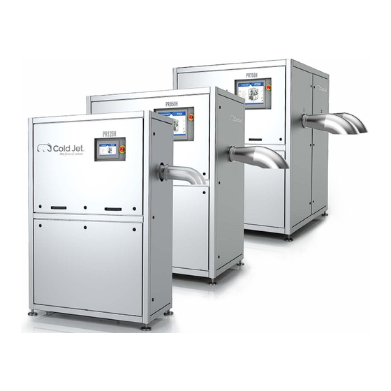
Dry Ice Manufacturing System - Pelletizers
PR120H | PR350H | PR750H
The Cold Jet Project Lead and Customer Project Lead who will oversee the successful
installation of the pelletizer and maximize the performance of the new dry ice manufacturing
system:
Cold Jet Project Lead
Customer Project Lead
Original [EN]
Telephone
Telephone
Email
Email
Oct 2019
Advertisement
Chapters
Table of Contents

Related Manuals for Cold Jet PR350H


Summary of Contents for Cold Jet PR350H
- Page 1 Dry Ice Manufacturing System - Pelletizers PR120H | PR350H | PR750H The Cold Jet Project Lead and Customer Project Lead who will oversee the successful installation of the pelletizer and maximize the performance of the new dry ice manufacturing system:...
- Page 2 Cold Jet and the client and remains the exclusive property of Cold Jet. If you find any problems in the documentation, please report them to us in writing. Cold Jet does not warrant that this document is error-free.
-
Page 3: Table Of Contents
Pre-Installation Guidelines & Checklist Contents Introduction ................................1 Unpacking & Inspecting ...........................2 Transporting & Lifting ............................3 Pre-Installation by the Customer ........................4 Dry Ice Production System ..........................6 Options & Accessories ...........................13 Safety ..................................20 Pre-Installation Checklist ..........................21 Notes ..................................22 Contact Information ............................24... -
Page 5: Introduction
Pre-Installation Guidelines & Checklist Introduction Before any pelletizer can be installed, the owner/operator must prepare the site for installation and operation. It is the owner’s responsibility to verify all the necessary preparations have been made to the installation site and meet the specifications and guidelines detailed in this publication. -
Page 6: Unpacking & Inspecting
Cold Jet's project lead (refer to the "Cold Jet Project Lead" on the front page or the contact details of the appropriate office on the last page). -
Page 7: Transporting & Lifting
Always transport the machine in the upright position using a forklift. Pick up the machine from the side with the forks fully engaged and adjusted to the maximum width (refer to "Figure 1: Transporting and Lifting the Machine."). Forklift Requirements PR120H PR350H PR750H Load Capacity 1000 kg (2205 lb) 1500 kg (3307 lb) -
Page 8: Pre-Installation By The Customer
Pre-Installation of the machine at the site must be carried out by the owner/operator. After that, a Cold Jet technician will arrive on-site for the final commissioning, start-up, and training. Machine owner/operators are responsible for the physical installation, utility connections, and supply required to put a new machine into service. - Page 9 Pre-Installation Guidelines & Checklist Figure 2: Minimum clearances...
-
Page 10: Dry Ice Production System
Pre-Installation Guidelines & Checklist Dry Ice Production System... - Page 11 Pre-Installation Guidelines & Checklist...
- Page 12 In order to achieve a consistent, high-quality supply of liquid CO to the pelletizer (especially the low-capacity pelletizer PR120H), Cold Jet recommends the installation of an automatic gas venting system, such as the Armstrong Kit (refer to "Figure 3: Degasser (Armstrong) Kit.
- Page 13 Additionally, the CO exhaust could have a temperature as low as -27°C (-16.6°F) which may generate condensation. Cold Jet recommends installing an Armaflex insulation or similar product to prevent this condensation from dripping down onto the machine or production room floor.
- Page 14 Before startup, verify the direction of rotation is the same as indicated on the motor for the hydraulic pump and on the motor for the oil cooler pump, if applicable. Electrical Service & Supply PR120H PR350H PR750H Voltage AC/ Frequency (EU 50Hz) 3 x 400 VAC/50Hz...
- Page 15 Cold Jet Connect™ is your access to quick and effective remote technical support. Via the internet, a Cold Jet technician can view the machine data in real time and support the owner/ user in for continued optimized machine performance or quick diagnostic of other uptime related issues.
- Page 16 Jet technician fill the tank prior to the commissioning and start up of the machine. The approximate volume and oil type is listed in the table below: Hydraulic Oil (Initial Filling) PR120H PR350H PR750H Hydraulic Reservoir Capacity (Max Filling) 80 l (21.1 gal) 180 l (47.6 gal)
-
Page 17: Options & Accessories
16 mm Item No. Item No. Item No. PR120H Not Available 512986 512692 514759 Item No. Item No. Item No. Item No. PR350H 503221 515650 501327 514103 Item No. Item No. Item No. Item No. PR750H 503221 515650 501327 514103... - Page 18 Pre-Installation Guidelines & Checklist Heating for Automatic Die Changer PR350H item 513034 PR750H, item 502970 If the pelletizer is placed in an operational environment where the exchanging of die plates is frequent and quick, the heating module will prevent water ice build-up on the die plate tool exchange system and allows for an effective die plate exchange in less than five minutes.
- Page 19 (7.87 in) and result in a total distance of 100 mm (3.97 in) between the floor and a standard discharge chute. This option is recommended if the dry ice container/tote being used is taller than 800 mm (31.5 in). This option is available for PR120H, PR350H, and PR750H. Sub-Frame PR350H Sub-Frame, item 513751...
- Page 20 Pre-Installation Guidelines & Checklist Cold Weather Kit PR350H Cold Weather Kit, item 515682 PR750H Cold Weather Kit, Item 515680 PR120H (400V) Cold Weather Kit, item 514558 PR120H (220V) Cold Weather Kit, item 514559 The cold weather kit heats the hydraulic oil and maintains a minimum temperature of 5°C.
- Page 21 Pre-Installation Guidelines & Checklist Warm Weather Kit PR350H Warm Weather Kit, item 515536 PR750H Warm Weather Kit, item 515533 The warm weather kit cools the hydraulic oil and maintains an optimal working temperature of the hydraulic oil below 50°C. This kit is recommended for pelletizers installed in locations where the ambient temperature is above 44°C (111°F) or the pelletizer will be producing non-...
- Page 22 15-inch HMI screen. The stainless steel enclosure (with cables) adds durability to the 15-inch external HMI. The optional extra external HMI and stainless steel enclosure (with cables) can be wall-mounted up to 10 m (33 ft) away from the machine. This option is available for PR120H, PR350H, and PR750H.
- Page 23 The system is based on the calculated produced volume per stroke of the pelletizer and is not based on a gravimetric weighing scale. The system can manage up to six difference container sized/production recipes. This option is available for PR120H, PR350H, and PR750H.
-
Page 24: Safety
Pre-Installation Guidelines & Checklist Safety Carbon Dioxide (CO ) and Dry Ice Properties At a temperature of -15°C (5°F) under normal atmospheric pressure, carbon dioxide has a density of 1.87 kg/m (0.12 lb/ft ) and is 1.5 times heavier than air. It is a colorless and odorless gas with a slightly pungent odor at higher concentrations and spreads along the ground. -
Page 25: Pre-Installation Checklist
I hereby verify the pre-installation preparations listed above have been completed. Customer: ___________________________________________________________________________________________ Order: _______________________________________________________________________________________________ Owner/Contact: _____________________________________________________________________________________ Signature ____________________________________________________________________________________________ Date: _________________________________________________________________________________________________ Notes/Remarks to Cold Jet: _________________________________________________________________________ Email the signed form to the to the Cold Jet project lead named on the front page... -
Page 26: Notes
Pre-Installation Guidelines & Checklist Notes... - Page 27 Pre-Installation Guidelines & Checklist...
-
Page 28: Contact Information
1727 Industrial Road, Unit 1 After Hours Support: +1-800-777-9101 Cambridge, Ontario N3H 5G7 Email: service@coldjet.com Latin America - Cold Jet Latinoamérica Phone: +52 (81) 1097-0445 San Alberto 404 P2 Col. Residencial After Hours Support: +1 (513) 576-8981 Santa Barbara Email: soporte.la@coldjet.com... - Page 29 PR120H Pelletizer OPERATOR MANUAL Original Instructions [English] 19-01-2023 Rev 3...
- Page 30 CONFIDENTIAL BETWEEN COLD JET AND THE CLIENT AND REMAINS THE EXCLUSIVE PROPERTY OF COLD JET. IF YOU FIND ANY PROBLEMS IN THE DOCUMENTATION, PLEASE REPORT THEM TO US IN WRITING. COLD JET DOES NOT WARRANT THAT THIS DOCUMENT IS ERROR-FREE.
- Page 31 CONTENT INTRODUCTION About the PR120H • SYSTEM DESCRIPTION Functional description • System identification • Supplier responsible for the equipment • TECHNICAL DATA - SAFETY REGULATIONS SAFETY REGULATIONS General Measures • Personnel Qualifications • Security and Risk • Safety Labels • Danger of Suffocation •...
-
Page 33: Introduction
The Cold Jet PR120H has a quick start-up that reduces downtime and loss of valuable CO2. This is secured by a start-up sequence purging the liquid line and using a special valve to fill the chamber. -
Page 35: System Description
Liquid CO2 is fed from an external CO2 tank (not part of this description – see supplier information) through an insulated pipe to the Cold Jet PR120H. It is recommended to use a gas separator to eliminate gaseous CO2 from the liquid CO2. -
Page 36: System Identification
System identification The machine is double marked with EU and UL approval. Example of a system identification, values and numbers may vary Supplier responsible for the equipment Cold Jet ApS Industrivej 68 DK-6740 Bramming Denmark Phone: +45 75 56 15 00 Homepage: www.coldjet.com... -
Page 37: Technical Data - Safety Regulations
TECHNICAL DATA - SAFETY REGULATIONS Rated Output: Kg/h: up to 120 / lbs/h: up to 265 Of high quality dry ice pellets, depending on the extruder plate applied Pellet Size: Diameter: Mm: 3 - 10 or 16 / Inch: 1/8 – 3/8 or 5/8 Cylindrical - length varying from: Mm: 50 to 100 / inch: 2 to 4 Inlet Liquid CO2 Pressure:... -
Page 39: Safety Regulations
The owner of the machine shall make sure that the operator, who is to work with the Cold Jet PR120H, fully understands the importance of studying the content of the manual and complying with the SAFETY REGULATIONS described on the following pages as well as those placed on the machine. -
Page 40: Safety Labels
Safety Labels The symbols used on the machine were developed by the International Organization for Standardization (ISO) and are defined below. These symbols may include yellow warnings triangles, blue mandatory action circles, or red prohibited action circles. Danger of Suffocation Dry ice pellets are CO in solid form. -
Page 41: Static Electricity
Static Electricity Dry ice can cause electrostatic discharges. However, the equipment is bonded to the ground to minimize electrostatic discharge, and the warning sign is meant to instruct the operator to avoid placing the equipment in rooms containing explosive gasses. It is recommended to use a plastic shovel in the dry ice container. -
Page 42: Wear Protective Gloves
Wear Protective Gloves While working with the conveyor system, the operator must wear protective gloves to avoid contact with the dry ice or with parts of the machine which are in direct contact with the dry ice. How to Lift / Transport 1. -
Page 43: Safety Operation
SAFETY OPERATION Emergency stop All equipment is connected to the general emergency system for PR350H. When an emergency-stop device is activated, all components located in the emergency zone will be disconnected from their power source. Machine safety There are machine safety measures in the following areas: Extruder unit •... -
Page 45: Machine Structure
MACHINE STRUCTURE PR120H 1 Pellets outlet sprout 2 Hydraulic station 3 Main hydraulic cylinder 4 Touch panel 5 Heat exchanger 6 Connection to external supply Version: PR120H Page: 11 of 14 User’s manual Date: 2023.01.19... -
Page 46: Machine Operation Start-Up
CO pipe are connected. Open ball valves for liquid CO supply and degassing. Turn the MAIN SWITCH on. To start up the Cold Jet PR120H, select the “Automatic mode” and press the “Start” button. MACHINE CONTROLS PR120H Version: PR120H... - Page 47 1 Start up page This page can be activated from any page by pressing the “Home button” in the lower right hand corner. 2 Start /Stop By activating the “Start / Stop” button, the machine starts or stops when in group mode. 3 Mode select By activating the “mode select”...
- Page 48 6 Process values By pressing the “gauge” button, the “process values” page is activated. The page contains a 2-column display of real time process values (PV). The corresponding “Set Values” (SV) are displayed next to the PV for comparison. During production, the PV will vary inside the given SV window.
- Page 49 PR120H Pelletizer MAINTENANCE AND REPAIR Original Instructions [English] 13-12-2022 Rev 5...
- Page 50 CONFIDENTIAL BETWEEN COLD JET AND THE CLIENT AND REMAINS THE EXCLUSIVE PROPERTY OF COLD JET. IF YOU FIND ANY PROBLEMS IN THE DOCUMENTATION, PLEASE REPORT THEM TO US IN WRITING. COLD JET DOES NOT WARRANT THAT THIS DOCUMENT IS ERROR-FREE.
- Page 51 Get a particle analysis of the oil if in doubt about the contamination degree. Cold Jet recommend the owner to have a spare part package in stock, so repairs can be made quickly and with a very little loss of production time.
- Page 52 This table includes all the service intervals from 0 hours to 20000 hours. For each service interval there will be listed which procedures is necessary to perform and the Cold Jet article no. for spare parts package. Table 1. Table for mechanical maintenance Pelletizer PR120H Service interval Hours/Month Procedure no.
- Page 53 PROCEDURES FOR MAINTENANCE AND REPAIR This table includes all the procedures for maintenance and repair. After locating procedure numbers in the table for service interval, you have to find the procedure numbers in the table below which will lead to detailed procedures on pages in the appendix. Contents MECHANICAL MAINTENANCE ............................
- Page 54 1. Procedure for changing CO filter and gasket on a PR120H This section will describe how to change the CO filter and gasket on a PR120H. During this operation it’s important to activate the emergency stop button! Disassembling the CO filter housing Remove the filter housing by loosening the 4 screws [1] and pull the filter housing end plate [2], gasket [3], filter [4] out wards.
-
Page 55: Procedures For Changing Degassing Filters On Pr120H
Notice! It is very important to be careful and not get any dust or dirt into the filter housing under this this could block the Danfoss solenoid valves Operation, 2. Procedures for changing degassing filters on PR120H During this operation it’s important to activate the emergency stop button! Version: PR120H Page:... - Page 56 Disassembling the degassing sleeves Remove the extruder plate by loosening 4 counter nuts and 4 nuts [4] for the extruder plate. Loosen the 6 screws [3] for the extruder cylinder and gently pull out the extruder cylinder. Replace 2 pcs o-rings [2] and 1 pcs degassing filter [1] and reassemble the extruder unit.
-
Page 57: Procedure For Changing Hydraulic Return Oil Filter On Pr120H
3. PROCEDURE FOR CHANGING HYDRAULIC RETURN OIL FILTER ON PR120H During this operation it’s important to activate the emergency stop button! Procedure step by step 1. Dismount the 4 screws [1] from the return oil filter housing [3]. 2. Remove the housing top plate [2]. 3. -
Page 58: Procedure For Changing Gaskets In Hydraulic Cylinders On Pr120H
4. PROCEDURE FOR CHANGING GASKETS IN HYDRAULIC CYLINDERS ON PR120H 1. Piston 4. Piston rod 3. Cylinder tube 2. Cylinder top During this operation it’s important to activate the emergency stop button! Important! For operators safety the hydraulic cylinder has to be disconnected from the hydraulic system before dismounting. Version: PR120H Page:... - Page 59 Procedure step by step 1. The hydraulic cylinder has to be emptied for oil. 2. Pos. 2 cylinder top is dismounted and screwed out of the cylinder tube pos. 3. 3. Pos. 1 piston, 2 cylinder top and 4 piston rod cylinder top are pulled out of the cylinder tube pos. 3. 4.
-
Page 60: Procedure For Changing The Hydraulic Cylinder On Pr120H
5. PROCEDURE FOR CHANGING THE HYDRAULIC CYLINDER ON PR120H During this operation it’s important to activate the emergency stop button! The hydraulic cylinder Disassembling the hydraulic cylinder from the process unit is done by first removing the 4 pcs. bolts [1] fixing the process unit the machine frame. - Page 61 The extruder piston and linear transduser Place the hydraulic cylinder on a workbench. Disassemble the piston from the hydraulic cylinder by loosening the 8 pcs. boltsand washers [6] and brackets [7]. Slide the piston [8] of the piston rod. Remove the linear transduser [9] by using a wrench and gently slide out the linear transduser. Fit the piston to the new or renovated hydraulic cylinder by fitting washers, lubricating and tightening the 8 pcs.
-
Page 62: Procedure For Changing Danfoss Ev3 And Ev15 Valves + Solenoids On Pr120H
6. PROCEDURE FOR CHANGING DANFOSS EV3 AND EV15 VALVES + SOLENOIDS ON PR120H During this operation it’s important to activate the emergency stop button! Disassembling and replace a Danfoss EV15 valve and solenoid Remove the pipe by loosening the 2 flare nuts [1] dismount the plug on the solenoid and pull of the solenoid [2], loosen the flare nut on this pipe [3], remove the EV15 valve [4]. -
Page 63: Procedure For Changing The Extruder Piston On Pr120H
7. PROCEDURE FOR CHANGING THE EXTRUDER PISTON ON PR120H During this operation it’s important to activate the emergency stop button! Follow instructions from Procedure 5 for disassembling the hydraulic cylinder and piston. The extruder piston Place the hydraulic cylinder on a workbench. Disassemble the piston from the hydraulic cylinder by loosening the 8 pcs. -
Page 64: Procedure For Changing Refill Filter On Pr120H
8. PROCEDURE FOR CHANGING REFILL FILTER ON PR120H Procedure step by step 1. Dismount the 6 screws [2] from the refill filter [1]. 2. Replace the refill filter. Make sure to replace the gasket [3] 3. Mount the 6 screws [2] again tightening evenly and firmly. 1. -
Page 65: Procedure For Changing Hydraulic Pump Or Repair On Pr120H
During this operation it’s important to activate the emergency stop button! Changing or repairing the hydraulic pump This operation is only to be carried out by Cold Jet service technician or by an Cold Jet approved company such as Bosch / Rexroth. -
Page 66: Procedure For Changing Oil On Hydraulic Station On Pr120H
10. PROCEDURE FOR CHANGING OIL ON HYDRAULIC STATION ON PR120H 1. Hydraulic tank 3. Cover plate 1. Ball valve During this operation it’s important to activate the emergency stop button! Procedure step by step 1. Remove the oil. Drain out off this ball valve pos. 1. The used oil must be deposited at an approved station for environmental waste. -
Page 67: Procedure For Replacement Of Gaskets In Pneumatic Ball Valves
11. PROCEDURE FOR REPLACEMENT OF GASKETS IN PNEUMATIC BALL VALVES Unplug the electrical connection and the pneumatic tube [1.1] for the actuator. Make sure that there is no pressure in the liquid CO2 and remove the flexible hose [1.7]. Remove the complete valve unit [1.2] by loosening the 4 screws [1.4], and place it on a desk. - Page 68 Description Material Indicator screw Stainless steel(304) Indicator Plastic(ABS) Circlip Stainless steel(304) Thrust washer Stainless steel(304) Outside washer polyoxymethylene Body Extruded aluminum alloy(6005-T5) Guide(piston) polyoxymethylene O-ring(pinion top) Bearing(pinion top) polyoxymethylene Inside washer polyoxymethylene Pinion Bearing (pinion bottom) polyoxymethylene O-ring(pinion bottom) Spring 0~12 Spring steel Bearing (piston)
- Page 69 Inspection and maintenance Inspect the components of the actuator for wear or damage and replace where necessary 13. Replace: On the pinion: O-ring [8], [14] On the end caps: End cap o-ring [25], O-ring (adjust screw) [20] On the pistons: O-ring [17] Assembly of the actuator Before beginning the assembly to check always that all the o-rings and gaskets that is compatible with buna or nitrile rubbers are properly housed in their lodgings, and all the components are greased correctly using a...
- Page 70 Starting position for 5 Springs 6 Springs installation of pistons 7 Springs 8 Springs 9 Springs 10 Springs 11 Springs 12 Springs 6. Fit the stroke adjustment screw [22] with the nut [21] and o-ring [20] in the body. Pressure test Pressure test the actuator with 6 bar (90 psig) compressed air and inspect for leaks using a soap and water solution sprayed on to all joints and rotating shafts.
- Page 71 POS. DESCRIPTION MATERIAL TYPE Body Stainless steel - AISI 316 End Cap Stainless steel - AISI 316L Ball Stainless steel - AISI 316 Seat PTFE with 25% carbon composit Joint Gasket PTFE Stem Stainless steel - AISI 316 Stem Seal PTFE with 25% carbon composit Stem Seal 75% PTFE, 20% glas fiber, 5%...
- Page 72 Inspection and maintenance Inspect the components of the valve for wear or damage and replace where necessary 2. Replace: Seat [4], Joint Gasket [5], Stem Seal [7] and [8] Assembly of the ball valve Before beginning the assembly always check that all the o-rings and gaskets are compatible and are properly housed in their lodgings, and all the components are greased correctly using standard commercial grease.
- Page 73 12. OPERATING IN SINGLE MODE CONTROL 1. Select single mode 2. Enter manual operation controls 1. Start the hydraulic pump 2. Move the pistons using valve 2 FWD and RWD buttons Check that there are no leaks on the hydraulic station. The operation is complete.
- Page 74 Pelletizer PR120H ALARMLIST 07-11-2022 Rev 2 Original Instructions [English]...
- Page 75 CONFIDENTIAL BETWEEN COLD JET AND THE CLIENT AND REMAINS THE EXCLUSIVE PROPERTY OF COLD JET. IF YOU FIND ANY PROBLEMS IN THE DOCUMENTATION, PLEASE REPORT THEM TO US IN WRITING. COLD JET DOES NOT WARRANT THAT THIS DOCUMENT IS ERROR-FREE.
- Page 76 Use table for troubleshooting to fix the error. In general, Cold Jet recommend that the cause of errors is investigated as soon as they appear and that the machine is not being operating until the error is identified or fixed.
- Page 77 Error. EtherCAT bus Chamber pressure G01-TP1 Error. Disconnected Chamber pressure G01-TP1 Error. Short circuit Chamber pressure G01-TP1 Error. Chamber pressure G01-TP1 Error. PV larger than SP Chamber pressure G01-TP1 Error. PV less than SP Chamber pressure G01-TP1 Error. EtherCAT bus Linear encoder G01-TG1 Error.
- Page 78 Error. Both 1 and 2 Hydraulic motor HU01-G1-MO1 Error. Both BG1 and BG2 Hydraulic motor HU01-G1-MO1 Error. Max actiontime Hydraulic motor HU01-G1-MO1 Error. Circuit breaker Hydraulic motor HU01-G1-MO1 Error. Inverter Hydraulic motor HU01-G1-MO1 Error. Hardware Hydraulic motor HU01-G1-MO1 Error. Hydraulic valve 1 HU01-Q1 Error.
- Page 79 Error. Disconnected Liquid CO2 pressure transmitter W01-TP1 Error. Short circuit Liquid CO2 pressure transmitter W01-TP1 Error. Liquid CO2 pressure transmitter W01-TP1 Error. PV larger than SP Liquid CO2 pressure transmitter W01-TP1 Error. PV less than SP Liquid CO2 pressure transmitter W01-TP1 Error.
- Page 80 TROUBLE SHOOTING TABLE Troubleshooting Alarm test Description Both_1_AND_2 Program error. More than one group started at a time. Contact IceTech technical support. Both_BG1_AND_BG2 Both sensors are active and shouldn't be. Investigate if both sensors are actually active and replace damaged component if needed.
- Page 81 Check if the is a short circuit in the component or the wiring to the component. PV_Larger_Than_SP Actual process value is larger than set point Check setpoint on HMI and investigate why the process value is too high. PV_Less_Than_SP Actual process value is less than set point Check setpoint on HMI and investigate why the process value is too low.
- Page 82 Max. purge time exceeded If purge limit within the given max. purge time this error occur. Check if liquid CO is available. Check if liquid CO2 filter is blocked, clean or replace if necessary. If this error happen frequently it could indicate that the liquid supply line is not properly insulated and/or that a degassing valve is required to achieve proper CO supply.
- Page 83 NOTES Version: R1000H Page: Alarmlist Date: 07.11.2022...
- Page 84 CONTACT INFORMATION Version: R1000H Page: Alarmlist Date: 07.11.2022...
- Page 85 PR120H Pelletizer USER MANUAL Original Instructions [English] 09-11-22 REV 5...
- Page 86 INFORMATION AND INTELLECTUAL PROPERTY CONTAINED HEREIN IS CONFIDENTIAL BETWEEN COLD JET AND THE CLIENT AND REMAINS THE EXCLUSIVE PROPERTY OF COLD JET. IF YOU FIND ANY PROBLEMS IN THE DOCUMENTATION, PLEASE REPORT THEM TO US IN WRITING. COLD JET DOES NOT WARRANT THAT THIS DOCUMENT IS ERROR-FREE.
- Page 87 ABLE OF ONTENTS Introduction About the PR120H System Description Functional description System Identification Supplier Responsible for the Equipment TECHNICAL DATA - SAFETY REGULATIONS TECHNICAL FACTS OF FROZEN CO2 SAFETY REGULATIONS General Measures Personnel Qualifications Security and Risk SAFETY OPERATION Emergency Stop Machine Safety Liquid CO2 Leakage Stop Production...
- Page 88 PR120H Version: Page: 3 of 26 User’s manual Date: 09.11.2022...
-
Page 89: Introduction
The Cold Jet PR120H has a quick start-up that reduces downtime and loss of valuable CO2. This is secured by a start-up sequence purging the liquid line and using a special valve to fill the chamber. - Page 90 PR120H Version: Page: 5 of 26 User’s manual Date: 09.11.2022...
-
Page 91: System Description
Liquid CO2 is fed from an external CO2 tank (not part of this description – see supplier information) through an insulated pipe to the Cold Jet PR120H. It is recommended to use a gas separator to eliminate gaseous CO2 from the liquid CO2. -
Page 92: System Identification
System Identification The machine is double marked with EU and UL approval. Example of a system identification, values and numbers may vary Supplier Responsible for the Equipment Cold Jet ApS Industrivej 68 DK-6740 Bramming Denmark Phone: +45 75 56 15 00 Homepage: www.coldjet.com... -
Page 93: Technical Data - Safety Regulations
TECHNICAL DATA - SAFETY REGULATIONS Rated Output: Kg/h: up to 120 / lbs/h: up to 265 Of high quality dry ice pellets, depending on the extruder plate applied Pellet Size: Diameter: Mm: 3 - 10 or 16 / Inch: 1/8 – 3/8 or 5/8 Cylindrical - length varying from: Mm: 50 to 100 / inch: 2 to 4 Inlet Liquid CO2 Pressure:... -
Page 94: Technical Facts Of Frozen Co2
TECHNICAL FACTS OF FROZEN CO2 Dry ice is frozen carbon dioxide (CO ). It is much denser and colder than traditional ice. Dry ice is -79°C (-109.3°F). Traditional ice is 0°C (32°F). In addition, dry ice does not melt - it sublimates. Sublimation is the process of going directly from solid form into gas form. Dry ice by-passes the liquid form, hence the “dry”... -
Page 95: Safety Regulations
The owner of the machine shall make sure that the operator, who is to work with the Cold Jet PR120H, fully understands the importance of studying the content of the manual and complying with the SAFETY REGULATIONS described on the following pages as well as those placed on the machine. - Page 96 Safety Labels The symbols used on the machine were developed by the International Organization for Standardization (ISO) and are defined below. These symbols may include yellow warnings triangles, blue mandatory action circles, or red prohibited action circles. Danger of Suffocation Dry ice pellets are CO in solid form.
- Page 97 Static Electricity Dry ice can cause electrostatic discharges. However, the equipment bonded to ground to minimize electrostatic discharge, and the warning sign is only meant to instruct the operator to avoid placing the equipment in rooms containing explosive gasses. Also, it is recommended to use a plastic shovel in the dry ice container. Danger of Congelation in solid form has a temperature of -79°C /-110°F or lower at atmospheric pressure and can therefore cause serious congelation injuries.
- Page 98 Wear Protective Gloves During work with the conveyor system, the operator must wear protective gloves in order to avoid contact with the dry ice or with parts of the machine which are in direct contact with the dry ice. How to Lift / Transport 1.
-
Page 99: Safety Operation
SAFETY OPERATION Emergency Stop All equipment is connected to the general emergency system for the Cold Jet PR120H. When an emergency-stop device is activated, all components located in the emergency zone will be disconnected from their power source. Machine Safety... -
Page 100: Machine Structure
MACHINE STRUCTURE PR120H 1 Pellets outlet sprout 2 Hydraulic station 3 Main hydraulic cylinder 4 Touch panel 5 Heat exchanger 6 Connection to external supply PR120H Version: Page: 15 of 26 User’s manual Date: 09.11.2022... -
Page 101: Machine Operation Start-Up
CO pipe are connected. Open ball valves for liquid CO supply and degassing. Turn the MAIN SWITCH on. To start up the Cold Jet PR120H, select the “Automatic mode” and press the “Start” button. PR120H Version: Page: 16 of 26 User’s manual... -
Page 102: Machine Controls
MACHINE CONTROLS PR120H 1 Start up page This page can be activated from any page by pressing the “Home button” in the lower right hand corner. 2 Start /Stop By activating the “Start / Stop” button, the machine starts or stops when in group mode. 3 Mode select By activating the “mode select”... - Page 103 5 Set point By pressing the “toothed wheel” button, the “Setpoint” (SV) page is activated. The “set point” section contains 3 pages display of set values for the current dry ice production. Fixed set points are password protected and have hardcoded limits to avoid unsafe production.
- Page 104 9 Shutdown before turning power off. When machine have finished production and there is a need for shutting down machine and turn power off it is needed to follow this procedure. Press mode select icon once and it changes into single mode.
-
Page 105: Repair And Warranty
Get a particle analysis of the oil if in doubt about the contamination degree. Cold Jet recommends that the owner has a spare parts package in stock, so repairs can be made quickly and with little loss of production time. -
Page 106: Terms Of Warranty
Cold Jet technician or by the owner’s qualified personnel who has been trained by Cold Jet in the repair and maintenance of Cold Jet dry ice blasting and dry ice production machines and accessories. -
Page 107: Instruction - Unpacking And Preparations Before Installation
The minimum clear distances must be observed to provide sufficient space for opening the cabinet doors and servicing the PR120H. Installation of the PR120H The installation of the PR120H must be carried out by one of Cold Jet’s service technician, or by a technician approved by Cold Jet. PR120H... - Page 108 DRAWING No. A1 Correct Handling of Cold Jet PR120H Minimum load capacity of forklift truck: 800kg/1764 lbs Minimum fork length: 0.8 m The PR120H is supplied with thread holes for lifting eyes. Always use lifting eyes to lift the PR120H.
-
Page 109: End Of Life For The Pr120H
DRAWING No. A2 End of life for the PR120H When the PR120H is at the end of its life, the following steps are required. Disconnect the power Disconnect the CO Drain the PR120H oil For handing of the PR120H read section Error! Reference source not found.. The materials and oil must be disposed of according to the jurisdictional rules and regulations for proper disposal. -
Page 110: Notes
NOTES PR120H Version: Page: 25 of 26 User’s manual Date: 09.11.2022... -
Page 111: Contact Information
Phone (US): +1-800-777-9101 455 Wards Corner Road Phone (Outside US): +1(513)576-8981 Loveland, Ohio 45140 Email: service@coldjet.com Canada - Cold jet Canada Phone: +1-800-337-9423 Ext. 501 1727 Industrial Road, Unit 1 After Hours Support: +1-(513) 576-8981 Cambridge, Ontario N3H 5G7 Email: service@coldjet.com... - Page 125 PROPRIETARY AND CONFIDENTIAL: THE INFORMATION CONTAINED IN THIS DRAWING IS THE SOLE PROPERTY O F ICETECH A/S. ANY REPRODUCTION IN PART OR AS A WHOLE WITHO U T THE WRITTEN PERMISSIO N OF ICETECH A/S IS PROHIBITED. =V01 Option =W01 =G01 T1 Liquid P1 Liquid...
- Page 126 7/9/2020 Tag-numbers for IceMaker PR120H P294-1-11991-G CE/UL 3x400V AC 50 HZ/3x480V AC 60 Hz. IceTech Varenummer Digital I/O Analog I/O ASPECT ASPECT DESCRIPTION TAG DESCRIPTION Beskrivelse Datablad relative links DIPR120H Dry Ice Production Unit DIPR120H=V01 Armstrong Kit Option DIPR120H=V01 Filter unit Valve for degassing filter unit 101099 032F101 00 EVR 15 DIPR120H=V01...
Need help?
Do you have a question about the PR350H and is the answer not in the manual?
Questions and answers