GE EntelliGuard G Installation, Operation And Maintenance Manual
Hide thumbs
Also See for EntelliGuard G:
- Installation, operation and maintenance manual (252 pages) ,
- Application manual (94 pages) ,
- Instructions manual (10 pages)

Related Manuals for GE EntelliGuard G


Summary of Contents for GE EntelliGuard G
- Page 1 EntelliGuard® G Circuit Breaker Installation, Operation, and Maintenance Manual Retain for Future Use. Courtesy of store.ips.us...
- Page 2 ©2012 General Electric All Rights Reserved Courtesy of store.ips.us...
- Page 3 Features may be described herein that result in death or serious injury. are not present in all hardware and software systems. GE Consumer & Industrial assumes no obligation of notice to holders of this document with respect to changes WARNING subsequently made.
-
Page 4: Table Of Contents
Table 2.3. EntelliGuard G Short Circuit and Interrupting Ratings: UL489 ..................9 Table 2.4. EntelliGuard G Non-Automatic Circuit Breaker: ANSI Version................... 10 Table 2.5. EntelliGuard G Non-Automatic Circuit Breaker/Molded Case Switch: UL Version ......... 10 Table 2.6. Key to Tables 2.2 Through 2.5 ..............................10 Table 2.7. - Page 5 DEH-41304C EntelliGuard® G Circuit Breaker 13 March 14 Table of Contents CLOSING PROCEDURE ........................................21 CONDITIONS WHEN CLOSING CANNOT OCCUR ..............................21 CIRCUIT BREAKER OPENING PROCEDURE ................................21 SECTION 5 – LOCKS AND INTERLOCKS GENERAL INFORMATION ........................................ 22 CIRCUIT BREAKER FRONT PANEL LOCKING ................................22 Pushbutton Locking ......................................
- Page 6 EntelliGuard® G Circuit Breaker DEH-41304C Table of Contents 13 March 2014 Table 6.17. Bell Alarm Ratings (Common NO/NC Contact Configuration) ..............31 Charging Spring Status Indicator ................................32 Table 6.18. Spring Charged Contact (1 NO) ..........................32 Secondary Disconnects (Factory-Installed/Field Installable) ..................... 32 Table 6.19.
-
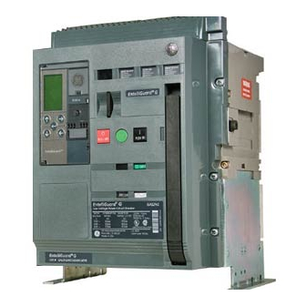
Page 7: Section 1 - General Information
See Section 2 for complete product specifications. INTRODUCTION Figure 1.1 shows a front view of the EntelliGuard G. The Quality Assurance indicated features are referenced in this document. All EntelliGuard G circuit breakers have been designed and manufactured to the highest technical standards. - Page 8 EntelliGuard® G Circuit Breaker DEH-41304C Section 1 – General Information 13 March 14 Figure 1.1. EntelliGuard G Power Circuit Breaker Features and Characteristics ©2012 General Electric All Rights Reserved Courtesy of store.ips.us...
-
Page 9: Section 2 - Product Specifications
<30 dB Endurance: closing coil, Shunt trip 20,000 operations motor operator, under voltage release, accessories 12,500 operations Table 2.2. EntelliGuard G Short Circuit and Interrupting Ratings: ANSI/UL1066 Interrupting Rating Tier ANSI/UL1066 Devices, LVPCB Envelope 1 Envelope 2 Envelope 3 Type... - Page 10 3200 5,000 5,000 5,000 4000 5,000 3,000 2,000 5000 5,000 2,000 1,500 Table 2.5. EntelliGuard G Non-Automatic Circuit Breaker/Molded Case Switch: UL Version* Envelope Type Amps Short Rated Endurance Interrupting Minimum Mechanical Minimum Electrical Minimum Electrical Current (kA) Endurance Endurance at 480 V...
- Page 11 DEH-41304C EntelliGuard® G Circuit Breaker 13 March 14 Section 2 – Product Specifications Table 2.8. Product Dimensions and Weights – ANSI/UL Width Depth Height Weight Type Design lbs. 3-pole Fixed breaker - back connected 13.50 17.17 17.40 136.7 Envelope 1, Top Mounted, UL/ANSI Drawout breaker - Moving portion 13.07 16.34 17.24...
-
Page 12: Section 3 - Lifting, Mounting And Installation
CIRCUIT BREAKER UNPACKING (Fig. 3.1) EntelliGuard G circuit breakers consist of rigid front and rear housings made of thermoset composite resins which 1. Inspect the shipping container for obvious signs of provide high structural strength and excellent dielectric rough handling and/or external damage incurred during properties. -
Page 13: Lifting And Mounting
DEH-41304C EntelliGuard® G Circuit Breaker 13 March 14 Section 3 – Lifting, Mounting and Installation Fixed portion: consists of a main fixed contact which is Drawout Cassette Lifting, Mounting and Installation brazed to a conductive pad, and arc runner which is Place the cassette on a rigid, leveled appropriate fastened to the conductive pad which guides the arc to support on the switchboard. -
Page 14: March
EntelliGuard® G Circuit Breaker DEH-41304C Section 3 – Lifting, Mounting and Installation 13 March 14 Figure 3.10. Circuit Breaker in Disconnected Position. Figure 3.7. Circuit Breaker Lifting Remove any padlocks and keep the key in place for key locks if applied from the racking panel of the cassette. Push back both the extended rails of the cassette to the Ensure the cassette position indicator shows stowed position. -
Page 15: Circuit Breaker Removal From The Cassette
DEH-41304C EntelliGuard® G Circuit Breaker 13 March 14 Section 3 – Lifting, Mounting and Installation 13. With a screwdriver, turn the racking handle shutter Circuit Breaker Removal from the Cassette DANGER drive A clockwise (Fig. 3.14). ELECTROCUTION Figure 3.14. Racking Handle Shutter Drive Location ... -
Page 16: Fixed-Mounted Circuit Breaker Mounting
A Mounting Location TRIP UNIT General Information All EntelliGuard G power circuit breakers are equipped with 3. Release the lever once the trip unit is inserted. This a digital electronic trip unit available in four basics versions action will lock the trip unit to the PMU base as shown in E, S, N, and H. -
Page 17: Wiring
DEH-41304C EntelliGuard® G Circuit Breaker 13 March 14 Section 3 – Lifting, Mounting and Installation WIRING Tables 3.1 through 3.3 show the wiring schematic for Blocks-A, -B and -C. Table 3.4 provides information on the factory- installed network interlock feature and is for use by maintenance organizations for optional network interlock connections. Table 3.5 provides nomenclature definitions for Tables 3.1 through 3.4. - Page 18 EntelliGuard® G Circuit Breaker DEH-41304C Section 3 – Lifting, Mounting and Installation 13 March 14 Table 3.4. Electronic Interlock Network Interlock Connections Network Interlock Status Switch NI TRIP NI TRIP NI RESET NI RESET NI NC NI NO NI COM 1.9 A 1.9 A 1.9 A...
-
Page 19: Secondary Disconnect Blocks
DEH-41304C EntelliGuard® G Circuit Breaker 13 March 14 Section 3 – Lifting, Mounting and Installation SECONDARY DISCONNECT BLOCKS Table 3.6. Terminal Wiring Number of Terminals Located for easy customer wiring to the accessories Terminal capacity and to the trip unit: Screw type (bare 12 AWG, - Top-mounted for all envelopes. -
Page 20: Section 4 - Operation
EntelliGuard® G Circuit Breaker DEH-41304C Section 4 – Operation 13 March 14 SECTION 4 – OPERATION Circuit Breaker Charging The circuit breaker can be charged in one of two ways: Manually, using a charging handle. WARNING The charging handle lies flush within the circuit IMPROPER INSTALLATION, OPERATION AND breaker front cover. -
Page 21: Closing Spring Discharge Procedure
DEH-41304C EntelliGuard® G Circuit Breaker 13 March 14 Section 4 – Operation CLOSING SPRING DISCHARGE PROCEDURE (Table 4.2) CLOSING PROCEDURE The main spring may be discharged (also known as Pull the charging handle out and down to charge the “crashing the mechanism”) without closing the breaker by closing springs (requires approximately 10 pumps of using a special tool operated through a small window on... -
Page 22: Section 5 - Locks And Interlocks
EntelliGuard® G Circuit Breaker DEH-41304C Section 5 – Locks and Interlocks 13 March 14 SECTION 5 – LOCKS AND INTERLOCKS CIRCUIT BREAKER FRONT PANEL LOCKING Pushbutton Locking DANGER This function denies unauthorized access to ON/OFF ELECTROCUTION pushbuttons. Ensure the circuit breaker has been tripped, indicating OFF, and the main springs are fully discharged before 1. -
Page 23: Key Lock For Breaker Trip Free Condition
DEH-41304C EntelliGuard® G Circuit Breaker 13 March 14 Section 5 – Locks and Interlocks Key Lock for Breaker Trip Free Condition Figure 5.5. Padlock Insertion and Lock-Out on the Security Locking Bar A total of four key locks (Ronis/Profalux/Kirk and one Castel lock) can be installed. -
Page 24: Door Interlock Installation
EntelliGuard® G Circuit Breaker DEH-41304C Section 5 – Locks and Interlocks 13 March 14 Fig. 5.7. Safety Shutter in Closed Position To assemble (Fig. 5.10): Place the spring over the pivot pin protruding from cassette side plate. Position interlock lever as shown. Ensure one end of spring is located below the nut and the other rests over the small boss on the lever. -
Page 25: Key Locks And Installation
DEH-41304C EntelliGuard® G Circuit Breaker 13 March 14 Section 5 – Locks and Interlocks Figure 5.12. Right-Hand Hinged Board Door Bracket Figure 5.14. Ronis Key Interlock Location Detail TWO-BREAKER CABLE INTERLOCK INSTALLATION Ensure the circuit breaker is in the DISCONNECTED POSITION. -
Page 26: Horizontal Mounting
EntelliGuard® G Circuit Breaker DEH-41304C Section 5 – Locks and Interlocks 13 March 14 Horizontal Mounting (Fig. 5.16) SAFETY SHUTTERS INSTALLATION (Fig. 5.17) Measure distance ”A” from the right hand face of one cassette to the right hand face of the other. Ensure circuit breaker is in the DISCONNECTED position Ensure the minimum cable radius is not less than and the racking handle is removed. -
Page 27: Section 6 - Accessories Description
The unique motor/gearbox unit is specially designed to incorporates easy-fit design features for quick installation, operate with the full range of EntelliGuard G. It is easily either at the factory or in the field (Fig. 6.1). fitted with three heavy-duty bolts. After a breaker close NOTE: Replacement accessories have an “R”... -
Page 28: Circuit Breaker Closing Coils - Standard And Commanded
EntelliGuard® G Circuit Breaker DEH-41304C Section 6 – Accessories Description 13 March 14 Circuit Breaker Closing Coils – Standard and Commanded Table 6.3. Extended Range Shunt Trip for UL Ground Fault and ANSI DC Rating Applications. Two, easy-to-fit, clip-on closing coil options with simple, plug-in connections are available. -
Page 29: Time Delay Module (Tdm) For Uvr (Externally Mounted)
DEH-41304C EntelliGuard® G Circuit Breaker 13 March 14 Section 6 – Accessories Description Remote Operation Coil Combination Table 6.5. UVR Operating Characteristics Each breaker accepts a maximum of four coils in the combinations shown in Table 6.7. All coils are mounted from Power Nominal Control Catalog... -
Page 30: Circuit Breaker - Key Interlock Facility
6.10). (Please contact our technical customer service department if longer length is required.) NOTE: Locks and keys are not supplied by GE. Please order separately from your local supplier. Mechanical interlocks can be fitted to electrical systems as shown in Table 6.13 and can link 2 and/or 3 circuit Table 6.10. -
Page 31: Bell Alarm With Lockout
DEH-41304C EntelliGuard® G Circuit Breaker 13 March 14 Section 6 – Accessories Description Table 6.15. Interlock Configurations Typical Circuit Interlock Configuration Possible Combinations Type A 1 from 2 way interlock 2 cable configuration Interlocking between two circuit breakers One normal power supply B1 can close only if B2 is open. -
Page 32: Charging Spring Status Indicator
EntelliGuard® G Circuit Breaker DEH-41304C Section 6 – Accessories Description 13 March 14 Charging Spring Status Indicator Neutral Rogowski CT’s Factory-installed on the motor, this auxiliary switch The Neutral Rogoswki CT’s are used to measure the indicates that the circuit breaker is charged and is Neutral Current and is required when Internal Ground standard with the spring-charging motor (Table 6.18). -
Page 33: Ready To Close Contact
There is no standing closing order. Front Flat Terminations There is no standing opening order. The EntelliGuard G Fixed mounted breaker comes standard with Back Connected Terminations. Optional Table 6.22. Ready to Close Contacts (1 NO) Front Flat terminations are available for front access Ratings Cat. -
Page 34: Section 7 - Accessories Installation
EntelliGuard® G Circuit Breaker DEH-41304C Section 7 – Accessories Installation 13 March 14 SECTION 7 – ACCESSORIES INSTALLATION Pull the charging handle while easing the cover upwards (Fig. 7.2). DANGER Figure 7.2. Charging Handle Position for Cover Removal ELECTROCUTION Ensure the circuit breaker has been tripped, indicating OFF, and the main springs are fully discharged before installing accessories. -
Page 35: Shunt Trip, Closing Coil And Under Voltage Release Device Installation
NETWORK INTERLOCK INSTALLATION Figure 7.4. Device Location When the network interlock is used with the EntelliGuard G, it will use the C and D positions of the coils as shown in Fig. 7.4. The mounting procedure is same as the coils. -
Page 36: Carriage Position Switch Installation
EntelliGuard® G Circuit Breaker DEH-41304C Section 7 – Accessories Installation 13 March 14 Remove the circuit breaker from its cassette. Each switch has a 1.5 m long wire for each switch Rotate the shutter operating lever to open the shutter terminal. -
Page 37: Upper Cluster Contact Set Grounding
DEH-41304C EntelliGuard® G Circuit Breaker 13 March 14 Section 7 – Accessories Installation Figure 7.13. Cluster Views Lower Cluster Contact Set Grounding (Figs. 7.15 and 7.16) 1. Using the cluster pliers, remove the lower cluster contacts at the rear of the circuit breaker. 2. -
Page 38: Mechanical Operations Counter Installation (Optional)
EntelliGuard® G Circuit Breaker DEH-41304C Section 7 – Accessories Installation 13 March 14 Connect the wires via the plug connectors to the REJECTION FEATURE respective locations of the secondary isolating contacts A33, A34 and A35 (Fig. 7.18). This factory-installed, pin and gate device prevents the insertion of a circuit breaker into a cassette if the nominal Figure 7.18. -
Page 39: Section 8 - Maintenance, Testing And Troubleshooting
DEH-41304C EntelliGuard® G Circuit Breaker 13 March 14 Section 8 – Maintenance, Testing and Troubleshooting SECTION 8 – MAINTENANCE, TESTING AND The back edge of each contact tip should line up with the outer edge of the marked area on the wear indicator. As the TROUBLESHOOTING contacts erode, the gap between the back of the contact tip and the rear housing becomes smaller. -
Page 40: Circuit Breaker Main Mechanism Inspection
EntelliGuard® G Circuit Breaker DEH-41304C Section 8 – Maintenance, Testing and Troubleshooting 13 March 14 Inspect the arc splitter plates and sides of the moldings Isolating Contacts (Drawout Type) Inspection for signs of wear or damage. Replace as necessary. Remove the circuit breaker from the cassette housing With the circuit breaker in the ON position, check the and place it on a suitable working surface. -
Page 41: Troubleshooting
DEH-41304C EntelliGuard® G Circuit Breaker 13 March 14 Section 8 – Maintenance, Testing and Troubleshooting TROUBLESHOOTING Table 8.1 reviews common problems, their possible cause(s) and solution(s). If problems persist please contact our After Sales Service Department at 1-888-GERESOLVE. (1-888-437-3765). Table 8.1. Troubleshooting Problem Possible Cause Solution... -
Page 42: Publications
EntelliGuard® G Circuit Breaker DEH-41304C Section 8 – Maintenance, Testing and Troubleshooting 13 March 14 EntelliGuard G Publications ® To download publications like those shown below, visit www.geelectrical.com. Publications Pub # EntelliGuard® G Application Guide DET-653A Time Current Curves: EntelliGuard TU Trip Unit for EntelliGuard G;... - Page 43 DEH-41304C EntelliGuard® G Circuit Breaker 13 March 14 Section 8 – Maintenance, Testing and Troubleshooting NOTES: ©2012 General Electric All Rights Reserved Courtesy of store.ips.us...
Need help?
Do you have a question about the EntelliGuard G and is the answer not in the manual?
Questions and answers