Table of Contents
Advertisement
DEH41549 R05
EntelliGuard * R Retrofill
Circuit Breakers 800-5000A
Installation Manual for R3 & R6 Type Retrofill Circuit Breakers replacing
Drawout Letter Code B, D & F Legacy AKR Circuit Breakers used in
AKD-8 & Substructures.
General Electric AKD-8 Low Voltage Switchgear is a free-standing
assembly of metal-enclosed power circuit breakers. It may also be
part of a single-ended or double-ended load center unit substation.
This manual applies to EntelliGuard R breakers to be used in AKD-8
Switchgear & substructures found in OEM Equipment and GE
Switchboards using legacy AKR circuit breakers of the following types:
800-2000A, AKR-#D-30/50/T50 circuit breakers in all Equipment types.
3200, 4000 & 5000A, AKR-#D-75/100/125 for AKD-8 switchgear,
AKR-#B-75/100/125 types in OEM equipment and AKR-#F-75/100/125
types in GE switchboards.
(# is shown in place of a number which designates the trip unit type.)
Advertisement
Table of Contents

Related Manuals for GE EntelliGuard AKR30S-800A


Summary of Contents for GE EntelliGuard AKR30S-800A
- Page 1 This manual applies to EntelliGuard R breakers to be used in AKD-8 Switchgear & substructures found in OEM Equipment and GE Switchboards using legacy AKR circuit breakers of the following types: 800-2000A, AKR-#D-30/50/T50 circuit breakers in all Equipment types.
-
Page 2: Table Of Contents
Trademarks and Patents ......................................6 Standards ............................................6 Document Conventions ......................................7 Related Publications ........................................7 Service and Support: Service and support always available from GE Energy................7 Estimated Time to Complete Tasks ..................................7 Product Specs ..........................................7 Weight (lbs.) ..........................................7 Views ............................................... - Page 3 Remove Circuit Breaker from Container ................................. 20 Inspect.............................................. 20 Store Circuit Breaker .............................. 20 Check Before Installing............................21 Clean and Grease Breaker ............................. 22 Modify Retrofill ................................. 23 Modify AKD-8—AKR30S Switchgear Compartment, Only ................23 AKD-8 AKR-30S—Remove Glastic Sheet of compartment ........................24 AKD-8 AKR-30S —Modify Bracket ..................................
- Page 4 AKD-8-Neutral CT Adapter 400A-5000A ................................. 57 Procedures ............................................. 58 AKD-8—Multi-Source Ground Fault ................................... 59 EntelliGuard R Circuit Breaker Retrofill AKD-8 Installation Manual DEH41549 R05...
-
Page 5: Preface
Preface Hazards The following important highlighted information appears throughout this document to warn of potential hazards or to call attention to information that clarifies a procedure. Carefully read all instructions and become familiar with the devices before trying to install, operate, service, or maintain this equipment. Danger This indicates a hazardous situation which, if not avoided, results in death or serious injury. -
Page 6: Warning
Warning This indicates a hazardous situation, which, if not avoided, would result in death or serious injury. A variety of electrical hazards warnings are displayed here and are applied to installation manuals. These are standard or generic alerts and labels that must be taken quite seriously when installing Retrofill circuit breakers in AKD switchgear and when working equipment that can cause injury, but may not be necessarily fatal (Table 3). -
Page 7: Notice Or Note
Features may be described herein that are not present in all hardware and software systems. GE Energy assumes no obligation of notice to holders of this document with respect to changes subsequently made. GE... -
Page 8: Document Conventions
GE in AKD-8 switchgear from 1979 to 2015. GE type TSVG… neutral CT’s are compatible. The old GE SST Neutral CT’s are not. Neutral sensors working with any Non-GE trip units installed as the result of a Trip unit conversion kit should be assumed to be incompatible with the NCT Adapter. -
Page 9: Views
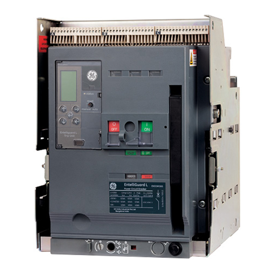
Views Typical R3 & R6 EntelliGuard R retrofill breakers are shown below. All breakers are drawout types. Each breaker is constructed by permanently joining an EntelliGuard G circuit breaker in a steel frame, installing primary and secondary disconnects and driving drawout racking cams thru what looks like the EntelliGuard G Cassette’s front dashboard. -
Page 10: History And Types
History and Types AK—Power Circuit Breaker Equipment D—Drawout circuit breaker construction Manufactured from 1951 to 1975, all bolted, copper bus design, all drawout breakers—AK-1, —2, —3,—15 / 25 / 50 / 75 / 100; with a 4000A-max bus rating. Breakers had a ratcheting drawout mechanism, with an open- door drawout. -
Page 11: Akd-8-Akr-30/30H/30L, Akr-50/50H/T50H, Akr-75/75H, Akr-100, Akr125
“picture frame” similar to the small frame breakers. The positions DISC/TEST/CONN are shown on the side of the front escutcheon by position of the sliding “picture frame”. The GE AKD-8 breakers have a drawout letter code “D”. OEM versions are drawout letter code “B” and GE Switchboard versions are drawout letter code “F”. -
Page 12: Akd-8-Retrofill Breaker
AKD-8—Retrofill Breaker AKD-8-Breaker Models The Table 7 depicts the key differences between Model 1 & 2 AKD8 Retrofill breakers (800-1600A). Note: All features of Model 2 (800-1600A) Retrofill breakers are incorporated in all the 2000A breakers. Table 7. AKD-8—Model 1 & 2 Retrofill Breakers Model 2 Retrofill Breaker* Feature Model 1 Retrofill Breaker (800-1600A) - Page 13 Table 7A. AKD-8—Retrofill Breakers (AKR75/75H,AKR100,AKR125) Feature Retrofill Breaker (3200-5000A) Secondary disconnect bullets Secondary mounted directly on metal bracket Disc Bullet as on the legacy AKR breakers mounting Kirk lock AKD-8 compartment Kirk lock can Actuator/ lockout all 3200-5000A EntelliGuard Compartment R types Release lever Kirk lock...
-
Page 14: Akd-8-Mechanical Drawings
AKD-8—Mechanical Drawings The following engineering or assembly drawings describe the layout and dimensions of the AKD-8 Retrofill breaker (Figure 2, Figure 3, Figure 4, Figure 5). Figure 2. AKD-8—AKR30/30H—Retrofill Breaker, Dimensioning Figure 3. AKD-8—AKR30S—Retrofill Breaker, Dimensioning EntelliGuard R Circuit Breaker Retrofill AKD-8 Installation Manual DEH41549 R05... - Page 15 Figure 4. AKD-8—AKR50/50H/30L—Retrofill Breaker, Dimensioning (Model 1) R3 type Figure 5. AKD-8—AKR50/50H/30L/AKRT-50H—Retrofill Breaker, Dimensioning (Model 2) R3 type R6 type EntelliGuard R Circuit Breaker Retrofill AKD-8 Installation Manual DEH41549 R05...
- Page 16 Figure 5A. AKD-8—AKR75/75H/AKR-100—Retrofill Breaker, Dimensioning Figure 5B. AKD-8—AKR-125—Retrofill Breaker, Dimensioning EntelliGuard R Circuit Breaker Retrofill AKD-8 Installation Manual DEH41549 R05...
-
Page 17: Akd-8 Compartment
AKD-8 Compartment Interior View The figures (Figure 6, 7, 8 & 9) below present a Typical AKR-30/50/T50 AKD-8 compartment. Figure 7. AKD-8—(new) Empty Compartment, View 2, Figure 6. AKD-8—(new) Empty Compartment, View 1 Racks/Rails Extended Figure 8 is a photo of the interior of the AKD-8. The photos point out the shutter assembly and telescopic rails in the AKD-8. -
Page 18: Interior Components
Interior Components Figure 9 points out the major components of an AKD-8 compartment. Figure 9. AKD-8—Circuit Breaker Compartment (22-Inch) for AKR-30/50/T50 Breakers Interior View The figures Figure 6A, 7A, 8A & 9A below present a Typical 30” AKR-75/100 AKD-8 compartment. (AKR-125 is similar but 38”... -
Page 19: Interior Components
Figure 8A is a photo of the interior of the AKD-8. The photos point out the shutter assembly and Draw out tray assembly in the AKD-8. Figure 8A. AKD-8—Compartment Assemblies Locating Pins Draw out Tray Assembly Interior Components Figure 9A points out the major components of an AKD-8 compartment. Figure 9A. -
Page 20: Unpack Cb
Unpack CB • Turn off all power to switchgear. Tagout and lockout main source, up-stream or main breaker. • Failure to comply with these instructions will result in death or serious injury from severe burns caused by arc flashing that has exceedingly high temperatures. -
Page 21: Quality
Quality All EntelliGuard R circuit breakers have been designed and manufactured to ANSI standards. The design was based on the original requirements of the legacy switchgear and breakers. The product is manufactured in Burlington, Iowa; and is inspected using some of the same master gauges used on the legacy AK, AKR breakers to confirm electrical and mechanical performance, including rejections-features. -
Page 22: Check Before Installing
1. Store the circuit breakers in a clean, dry location in an upright position. 2. Make sure that the breakers are properly supported to prevent bending of the studs or damage to any of the breaker parts. Do not remove any protective grease until the assemblies are ready to be installed. -
Page 23: Clean And Grease Breaker
3. Clean those areas if necessary with a clean, lint-free rag and isopropyl alcohol or acetone. 4. Be sure to apply a thin film of electrical grease DH0HD38 (Mobilgrease 28) to the primary disconnect fingers (Figure 10/10A). GE Part #193A1751P1 is a 1 oz. tube of Mobilgrease 28. Figure 10. AKD-8—Primary Contacts or “Fingers” (Apply Figure 10A. -
Page 24: Modify Retrofill
Modify Retrofill WIRING • Before installing the breaker, the secondary disconnects must be wired to the EntelliGuard Breaker. • Wires with wire markers are provided on the Retrofill. Make sure that the switchgear wiring connection points match up with the original wiring of the cubicle. This ensures that all wiring connections are properly made. -
Page 25: Akd-8 Akr-30S-Remove Glastic Sheet Of Compartment
AKD-8 AKR-30S—Remove Glastic Sheet of compartment Figure 11. Remove Glastic Sheet – AKR-30S only The AKD-8 AKR30S switchgear compartments need this particular attention. The glastic sheet has to be removed (Figure 11). In some cases, however, it is possible that this sheet is not secured to the top of the cabinet properly, and was found to sag around the middle of the cabinet. -
Page 26: Install Akd-8 (800-2000A) Retrofill Breaker
Figure 12. Modify Bracket Steps for removing the bracket pin: 1. Remove the left bracket assembly (75C149309G061) from the compartment (Figure 12). The assembly is bolted to the side sheet. Remove (4) ¼-20 thread forming screws using a socket wrench and 3/8” hex socket. - Page 27 Use a chain and hook to lift the breaker from above. 5. For AKR30/30H/30L/50/50H/-T50H Breakers same arrangement as above can be used to lift breaker Use GE part number 0247B8961G002 lifting bar and suitable hoist to lift from above as shown in Figure Figure 13. AKD-8—Location of Eyebolts Figure 14.
- Page 28 11. Remove the racking tool (Figure 15) from the storage location on the breaker front panel and extend the torque bar from inside the handle. Figure 15. AKD-8—Racking Tool 12. Use a blade-type screwdriver in the slot or rack out lock of the breaker (Figure 16), and turn it clockwise to the right so that the racking handle shutter opens Figure 16.
-
Page 29: Akd-8-Racked-In
19. At the end of 37 rotations, the breaker is in its maximum travel position. At this point, the primary disconnect fingers have completely engaged with the primary bus stabs. 20. Remove and store the racking handle in it storage location. AKD-8—Racked-In The photo below shows one example of a racked-in AKD-8 Retrofill (Figure 17). -
Page 30: Install Akd-8 & Substructure Type 3200, 4000 & 5000A Retrofill Breaker
After the old breaker is removed and the compartment updated with any added features, and secondary wiring checked, the breaker can be installed in the GE AKD-8 Switchgear, GE Switchboard or OEM Equipment. Verify that the new breaker is in the DISCONNECT and OPEN position. -
Page 31: Akd-8-Racked-In
9. Remove the lifting bar and or chains. 10. Check for alignment of the optional Programmer disconnect on the left side in the compartment. (It is fragile and will break if not properly aligned). 11. Push the breaker into the compartment slowly while observing the programmer disconnect mating and watching for the alignment of the secondary disconnects and opening of the optional shutter. -
Page 32: Akd-8-Install Accessories
AKD-8—Install Accessories WIRING • Before installing the breaker, the secondary disconnects must be wired to the EntelliGuard R Breaker. • Wires with wire markers are provided on the breaker. Make sure that the switchgear wiring connection points match up with the original wiring of the cubicle. - Page 33 Figure 20. AKD-8—Seven Bullets to a Block, Three Blocks Figure 21. AKD-8—Seven Bullets to a Block, Three Blocks (Exploded View) (Model 1) The secondary disconnect block assemblies (Figure 21) for the AKD8 version of the EntelliGuard Retrofill can be purchased and installed. Here are the installation instructions: For Model 1 AKD8 Retrofill Breakers 1.
- Page 34 4. Replace bullet blocks that are found with faulty bullets. Even with only one non-working bullet, replace the whole block of bullets. 5. Place the secondary disconnect block on top of the horizontal plate that runs across the width at the rear of the breaker.
- Page 35 For AKD8 (AKR75/100/125) Retrofill Breakers Figure 22A. AKD-8—Seven Bullets to a Block, Three Blocks 1. If the EntelliGuard R Retrofill breaker order included (3) 7 point secondary disconnect blocks see step 2 otherwise skip past the wiring instructions. 2. Check that bullets, on top of the secondary disconnects, are not damaged and that they slide in to the blocks freely.
- Page 36 WIRING • Do not pinch/damage the wires while installing the secondary disconnect blocks. Figure 23. AKD-8—Seven Bullets to a Block, Three Blocks to a Retrofill (Photo View) Figure 24. AKD-8—Landed Wiring (Photo View) EntelliGuard R Circuit Breaker Retrofill AKD-8 Installation Manual DEH41549 R05...
-
Page 37: Wire Secondary Disconnect Assembly-Akr30/30H/50/50H/30L/30S,T-50H
Wire Secondary Disconnect Assembly—AKR30/30H/50/50H/30L/30S,T-50H As mentioned above, the secondary disconnect blocks are available with all blocks installed. In this case, the wires on the blocks will be routed through one side of the breaker and on the front. The wires on the front are left loose for ease of landing the wires in the breaker secondary Terminal Blocks. - Page 38 Figure 25. AKD-8—Secondary Disconnects Wiring Diagram Figure 26. AKD-8—Secondary Disconnects Wiring Diagram (Example for AKR30/30H/50/50H/T-50H,30L/75/100/125) (Example for AKR30S) EntelliGuard R Circuit Breaker Retrofill AKD-8 Installation Manual DEH41549 R05...
-
Page 39: Akd-8-Programmer Disconnects
• Tools needed: Philips Head screw driver, wire strippers, wire cutters. AKD-8—Programmer Disconnects WIRING • Before installing the breaker, the secondary disconnects must be wired to the breaker. • Wires with wire markers are provided on the breaker. Make sure that the switchgear wiring connection points match up with the original wiring of the cubicle. - Page 40 2. Identify the type of programmer disconnect assemblies to be installed on the Retrofill breaker. The programmer disconnect assembly to be assembled depends upon the type of legacy breaker that is being replaced. These are as follows: • AKR30/30H/50/50H/T50H/30/75/100/125L—In these, the programmer disconnect is mounted on the left side wall of the Retrofill breaker.
- Page 41 6. Disconnect the wires connecting the terminal block to the compartment programmer disconnect assembly. See Figure 27. 7. If the customer has chosen to install a 19-pin programmer disconnect assembly, replacing a 12-pin programmer disconnect assembly, the terminal block mounted on the compartment needs to be removed as well.
-
Page 42: Wiring And Completion
Wiring and Completion 1. Note that the breaker side programmer disconnect assemblies come pre-installed and wired from the factory, so no action needs to be done on the breaker. 2. Check that the compartment side programmer disconnect assembly wiring scheme matches that of the breaker side wiring scheme. -
Page 43: Remove And Replace
Remove and Replace The primary disconnect assembly is factory-adjusted to apply a 95 ± 10 lb. force to a 1/2-inch thick copper bar, inserted between the upper and lower fingers. Set this force range, in the field, by tightening the nuts to set the spring dimension shown in Figure 31. - Page 44 18. Be sure to apply a thin film of Mobilgrease 28 (D50HD38) to the contact areas which slide onto the switchgear stabs (See Figure 33, Step 2). This product is available in a 1-oz tube, GE Part #193A1751P1. Figure 33 summarizes the steps for working with the primary contacts.
-
Page 45: Mechanical Views
Mechanical Views Figure 34 provides further details. Figure 34. Fingers or Clusters, Mechanical View, and Notes EntelliGuard R Circuit Breaker Retrofill AKD-8 Installation Manual DEH41549 R05... -
Page 46: Remove And Replace- Akr-75/100/125
Remove and Replace- AKR-75/100/125 The primary disconnect assembly is factory-adjusted to apply a 95 ± 10 lb. force to a 1/2-inch thick copper bar, inserted between the upper and lower fingers. Set this force range, in the field, by tightening the nuts to set the spring dimension shown in Figure 35A/35B. - Page 47 16. Be sure to apply a thin film of Mobilgrease 28 (D50HD38) to the contact areas which slide onto the switchgear stabs (See Figure 37/38, Step 2). This product is available in a 1-oz tube, GE Part #193A1751P1. 17. Figure 37 (AKR75/75H) and figure 38 (AKR100/125) summarizes the steps for working with the primary contacts.
- Page 48 Figure 37. Steps in Exploded Views (AKR-75/75H) Figure 38. Steps in Exploded Views (AKR-100/125) EntelliGuard R Circuit Breaker Retrofill AKD-8 Installation Manual DEH41549 R05...
-
Page 49: Mechanical Views-Akr-75/100/125
Mechanical Views-AKR-75/100/125 Figure 39 provides further details. Figure 39. Fingers or Clusters, Mechanical View, and Notes AKR 75/75H AKR100/125 AKD-8—Position Switch Actuator Position switch actuator comes pre-installed on all versions of Retrofill EntelliGuard ACB. Hence, no installation is required. Retrofills provide the same electrical indication scheme as the legacy breakers (Figure 40 and Figure 41 and 41 A). - Page 50 Figure 40. Breaker Surfaces Activate Position Switch. EntelliGuard R Circuit Breaker Retrofill AKD-8 Installation Manual DEH41549 R05...
- Page 51 Figure 41. Breaker Surfaces Activate Position Switch. (Model 2) Figure 41A. Breaker Surfaces Activate Position Switch (AKR75/100/125). EntelliGuard R Circuit Breaker Retrofill AKD-8 Installation Manual DEH41549 R05...
-
Page 52: Akd-8-Shutter Actuation
AKD-8—Shutter Actuation AKD-8 LVS comes installed with shutter assemblies for protection of the live bus bars. EntelliGuard R breaker comes pre-installed with shutter (Figure 42 , Figure 43 and figure 43A) actuators which operate the opening of the shutters. Hence, no installation is required. Retrofills provide the same mechanical indication scheme as legacy breakers. -
Page 53: Install Door Interlock System
Install Door Interlock System • It must be ensured that the supply power to the compartment is turned off/ compartment is de-energized for all the incoming and outgoing circuits of the LVS prior to any work being conducted on it. •... - Page 54 Figure 45. AKD-8—Door Interlocking Components (Model 2) Figure below shows the components that make up the AKD-8 Retrofill door interlocking assembly. • Please remove the existing Door Interlock Actuators from the compartment for AKR-30/30H/50/50H & AKRT-50/50H • The Retrofill breaker has a Door Interlock Actuator Bracket mounted on breaker. Figure below shows the Door Interlock Actuator mounted on Retrofill Breaker for AKR-30/30H/50/50H &...
- Page 55 Figure 46. AKD-8 (AKR75/100/125)—Door Interlocking Components Figure below shows the components that make up the AKD-8 Retrofill door interlocking assembly. Figure below shows the Door Interlock Actuator mounted on Retrofill Breaker for AKR-75/100/125 Door Interlock Actuator (Screw Head) EntelliGuard R Circuit Breaker Retrofill AKD-8 Installation Manual DEH41549 R05...
-
Page 56: Akd-8- Kirk Key Interlock
AKD-8— Kirk Key Interlock The EntelliGuard R Retrofill circuit breakers (model 2 AKR-30/50/T50 and all 3200-5000A) provided as replacements for AKR 800-5000A frame circuit breakers have a trip interlock feature which will function using the AKD-8 compartment mounted Key Interlock. A label is provided with full instructions on how to operate the Legacy Key Interlock. -
Page 57: Install New Door
4. Inside the compartment, check the contact areas on each primary disconnect bar or cluster of fingers for foreign matter that may have accumulated. Clean those areas if necessary with a clean, lint-free rag and isopropyl alcohol or acetone. 5. Be sure to apply a thin film of electrical grease (red, D50H387) to the contact areas for better electrical connections inside the compartment. -
Page 58: Akd-8-Neutral Disconnect Assembly, Bus Compartment
The Neutral CT Adapter supports iron core Neutral sensors compatible with MicroVersa Trip, MVT RMS-9, MVT Plus & PM, Power Plus, Pro Trip and EntelliGuard TU rated from 150 to 5000 Amps as used in GE switchboards and switchgear from 1979-2015. It is available in five variations (shown in Table below). - Page 59 AKD-8—Rogowski Assemblies, Mechanical Views Figure 48 shows a typical Rogowski assembly. Figure 48. Neutral Bus Rogowski ASM 10108266 Procedures PRODUCT DAMAGE • Write down the orientation of the existing Iron core CT and the polarity of the connections. The orientation and polarity needs to be matched when the air core Rogowski is assembled in the cable compartment.
- Page 60 7. Replace the old CT assembly with the new Rogowski assembly on the horizontal bus bars and fasten it using the hardware previously removed. 8. Connect a “twisted pair” of wires from the compartment neutral disconnect to the Rogowski CT. In case of damaged wire, the same must be replaced with new ones as already mentioned.
- Page 61 Wiring Diagram for the AK/AKR Retrofill EntelliGuard R Circuit Breaker Retrofill AKD-8 Installation Manual DEH41549 R05...
- Page 62 EntelliGuard R Circuit Breaker Retrofill AKD-8 Installation Manual DEH41549 R05...
- Page 63 NOTES: EntelliGuard R Circuit Breaker Retrofill AKD-8 Installation Manual DEH41549 R05...
- Page 64 GE Energy Connections 41 Woodford Avenue Plainville, CT 06062 www.geindustrial.com © 2016 General Electric Company *Trademark of the General Electric Company and/or its subsidiaries DEH41549 R05 12/16 EntelliGuard R Circuit Breaker Retrofill AKD-8 Installation Manual DEH41549 R05...
Need help?
Do you have a question about the EntelliGuard AKR30S-800A and is the answer not in the manual?
Questions and answers