
Related Manuals for Toro 72542TE


Summary of Contents for Toro 72542TE
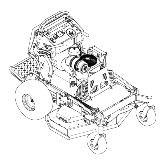
- Page 1 Form No. 3443-215 Rev A GrandStand ® Mower With 122cm Rear Discharge TURBO FORCE ® Cutting Unit Model No. 72542TE—Serial No. 400000000 and Up *3443-215* Register at www.Toro.com. Original Instructions (EN)
- Page 2 Whenever you need service, genuine Toro parts, or additional information, contact an Authorized Service Dealer or Toro Customer Service and have the model and serial numbers of your product ready. Figure 1 identifies the location of the model and serial numbers on the product.
-
Page 3: Table Of Contents
Contents Checking the Spark Arrester ......38 Fuel System Maintenance ........39 Draining the Fuel Tank ........39 Safety ............... 4 Removing the Fuel Tank ........39 General Safety ........... 4 Replacing the Fuel Filter ........40 Safety and Instructional Decals ......4 Electrical System Maintenance ...... -
Page 4: Safety
Safety • Keep bystanders and children out of the operating area. Do not allow children to operate the machine. Allow only people who are responsible, trained, This machine has been designed in consideration familiar with the instructions, and physically with EN ISO 5395. capable to operate the machine. - Page 5 decal116-8283 116-8283 decal131-3521 131-3521 1. Warning—read the Operator's Manual for instructions on torquing the blade bolt/nut to 75 to 81 N∙m (55 to 60 ft-lb). 1. Height of cut decal116-8775 116-8775 1. Read the Operator’s Warning—fill to the bottom Manual. of the filler neck;...
- Page 6 decal139-5557 139-5557 decal131-3536 131-3536 1. Thrown object 3. Entanglement hazard, hazard—keep bystanders belt—stay away from 1. Battery 4. Parking brake away. moving parts; keep all 2. Time 5. Engine—start guards and shields in place. 3. Power takeoff (PTO) 6. Engage the handle bars. 2.
- Page 7 decal131-3526 131-3526 1. Power takeoff (PTO)—disengaged 5. Reverse 2. Fast 6. Traction drive 3. Slow 7. Engage the handles. 4. Neutral decal139-5556 139-5556 5. Thrown object hazard—keep bystanders away. 1. Warning—read the Operator’s Manual. 2. Warning—do not operate the machine unless you are trained. 6. Warning—engage the parking brake, shut off the engine, and remove the key before leaving the machine or performing maintenance.
-
Page 8: Product Overview
Control Panel Product Overview g301785 Figure 4 1. Fuel cap 7. Key switch g273599 Figure 3 2. Choke control 8. Throttle control 3. Parking-brake lever 9. Height-of-cut lever 1. Front caster wheel 6. Operator cushion 4. Hydraulic-tank cap 10. Height-of-cut pin 2. -
Page 9: Specifications
(Figure To ensure optimum performance and continued safety certification of the machine, use only genuine Toro replacement parts and accessories. Replacement Throttle Control parts and accessories made by other manufacturers... -
Page 10: Before Operation
Operation – If you spill fuel, do not attempt to start the engine. Avoid creating a source of ignition until the fuel vapors have dissipated. Before Operation – Store fuel in an approved container and keep it out of the reach of children. •... -
Page 11: Performing Daily Maintenance
Performing Daily engine damage which may not be covered under warranty. Maintenance • Do not use gasoline containing methanol. • Do not store fuel either in the fuel tank or fuel Before starting the machine each day, perform the containers over the winter unless you use a fuel Each Use/Daily procedures listed in Maintenance stabilizer. -
Page 12: During Operation
Note: The clutch and blades/attachment should engage. Press the O position on the PTO switch. Note: The blades/attachment should stop. With the engine running, press the O position on the PTO switch without holding either motion-control lever to the center, unlocked position. - Page 13 • Do not use the machine as a towing vehicle. • Use only accessories and attachments approved by The Toro® Company. Slope Safety • Slopes are a major factor related to loss of control and rollover accidents, which can result in severe injury or death.
-
Page 14: Operating The Parking Brake
Operating the Parking Operating the Brake Mower-Blade-Control Switch (PTO) Always engage the parking brake when you shut off the machine or leave it unattended. Before each use, Use the blade-control switch (PTO) in conjunction with check the parking brake for proper operation. the motion-control levers to engage and disengage If the parking brake does not hold securely, adjust it;... -
Page 15: Operating The Throttle
Disengaging the Mower Blades Operating the Choke (PTO) Use the choke to start a cold engine. Figure 10 Figure 11 show 2 ways to disengage Pull up the choke knob to engage the choke the mower blades. before using the key switch (Figure 13). -
Page 16: Operating The Ignition Switch
Operating the Ignition Starting the Engine Switch Important: Do not engage the starter for more than 5 seconds at a time. If the engine fails to Important: Do not engage the starter for more start, wait 15 seconds between attempts. Failure than 5 seconds at a time. -
Page 17: Shutting Off The Engine
Shutting Off the Engine Operating the Platform You can use the machine with the platform in the CAUTION up or down position. It is your preference on which position to use. Children or bystanders may be injured if they move or attempt to operate the machine while WARNING it is unattended. -
Page 18: Driving Forward Or Backward
Driving Forward Disengage the parking brake; refer to Operating the Parking Brake (page 14). Move the motion-control levers to the center, unlocked position. g031026 Figure 18 1. Platform up 3. Pull the knob out to release the platform. 2. Platform down g030983 Figure 19 1. -
Page 19: Adjusting The Height-Of-Cut
Adjusting the Height-of-Cut The height-of-cut can be adjusted from 38 to 127 mm (1-1/2 to 5 inches) in 6 mm (1/4 inch) increments. Note: Using a height-of-cut under 51 mm (2 inches) increases the wear on the mower-deck belt. Use a height-of-cut that is greater than 51 mm (2 inches) whenever possible. -
Page 20: Using Weights
Using Weights After Operation • Install weights to improve balance. You can add or remove weights to create optimized performance After Operation Safety under different operating conditions and for your preference. General Safety • Add or remove weights 1 at a time until you achieve the desired handling and balance. -
Page 21: Using The Fuel-Shutoff Valve
Using the Fuel-Shutoff Pushing the Machine by Hand Valve The bypass valves allow you to push the machine by Close the fuel-shutoff valve for transport, maintenance, and storage (Figure 23). hand without the engine running. Important: Always push the machine by hand. Ensure that the fuel-shutoff valve is open when starting the engine. -
Page 22: Transporting The Machine
Transporting the Machine Use a heavy-duty trailer or truck to transport the machine. Use a full-width ramp. Ensure that the trailer or truck has all the necessary brakes, lighting, and marking as required by law. Please carefully read all the safety instructions. Knowing this information could help you or bystanders avoid injury. - Page 23 g031405 Figure 26 1. Back the machine up the 2. Walk the machine down ramp. the ramp. Shut off the engine, remove the key, and engage the parking brake. Tie down the machine near the front caster wheels and the rear bumper with straps, chains, cable, or ropes (Figure 27).
-
Page 24: Maintenance
To ensure optimum performance and continued the engine running. safety certification of the machine, use only • Carefully release pressure from components with genuine Toro replacement parts and accessories. stored energy. Replacement parts and accessories made by • Check the parking brake operation frequently. - Page 25 Maintenance Service Maintenance Procedure Interval • Change the engine oil. • Check, clean and gap the spark plug. • Check the battery. • Check the clutch. Every 100 hours • Check and clean the engine cooling fins and shrouds (more often in dirty or dusty conditions).
-
Page 26: Pre-Maintenance Procedures
Pre-Maintenance Opening the Engine Guard and Guard Extension Procedures Remove the bolt and shoulder nut securing the engine guard to the guard extension (Figure 29). Releasing the Cushion for Rear Access You can release the cushion for rear access to the machine for maintenance or adjustment. -
Page 27: Closing The Engine Guard And Guard Extension
Closing the Engine Guard Remove the 2 bolts (5/16 x 1 inch) and belt guard (Figure 31). and Guard Extension Install the extension guard as shown in Figure 32. Torque the nuts to 20 to 25 N∙m (15 to 18 ft-lb). -
Page 28: Removing The Left Belt Cover
Removing the Left Belt Cover Remove the 2 flange-head screws that secure the tensioner cover to the left belt cover, and remove the tensioner cover (Figure 34). g270474 Figure 36 1. Carriage bolt 3. Left belt cover 4. Flange locknut 2. -
Page 29: Removing The Right Belt Cover
Removing the Right Belt Cover Remove the 2 carriage bolts and 2 lock nuts that secure the right side CE cover to the right belt cover (Figure 38). g270475 Figure 38 1. Flange locknut 3. Right side CE cover 2. Right belt cover 4. -
Page 30: Installing The Right Belt Cover
Installing the Right Belt Assemble the right side CE cover to the right belt cover (Figure 41) with the 2 carriage bolts Cover and 2 lock nuts that you removed in Removing the Left Belt Cover (page 28). Assemble the right belt cover to the deck (Figure 40) with the 2 bolts that you removed in Removing the Left Belt Cover (page... -
Page 31: Installing The Left Belt Cover
Installing the Left Belt Cover Assemble the left belt cover to the deck (Figure 42) with the 3 bolts that you removed in Removing the Left Belt Cover (page 28). g270474 Figure 43 1. Carriage bolt 3. Left belt cover 4. -
Page 32: Lubrication
Lubrication Greasing the Machine Grease with No. 2 lithium or molybdenum grease. Disengage the PTO and set the parking brake. Shut off the engine, remove the key, and wait for all moving parts to stop before leaving the operating position. Clean the grease fittings with a rag. -
Page 33: Greasing The Front Caster Pivots
Greasing the Front Caster Note: Thread-locking adhesive has been applied to lock the spacer nuts to the axle. Pivots Remove the axle (with the other spacer nut still assembled to it) from the wheel assembly. Service Interval: Yearly Pry out the seals, inspect bearings for wear or Grease type: Lithium or molybdenum grease damage, and replace them if necessary. -
Page 34: Greasing The Motion Controls
Greasing the Motion Engine Maintenance Controls Engine Safety Service Interval: Yearly • Shut off the engine before checking the oil or Grease the operator-presence-control balljoint and adding oil to the crankcase. the motion-control bushing for both levers. • Keep your hands, feet, face, clothing, and other body parts away from the muffler and other hot Note: Use an oil drip between the lever brackets to... -
Page 35: Servicing The Engine Oil
Servicing the Engine Oil Note: Avoid knocking the filter into the side of the body. Remove the inner filter only to replace it. Engine-Oil Specifications Oil Type: Detergent oil (API service SJ or higher) Inspecting the Filters Engine Oil Capacity: 2.1 L (71 fl oz) with the filter; Inspect the safety filter. - Page 36 Changing the Engine Oil Service Interval: After the first 8 hours Every 100 hours Note: Dispose of the used oil at a recycling center. Park the machine so that the drain side is slightly lower than the opposite side to assure the oil g273859 drains completely.
-
Page 37: Servicing The Spark Plug
g273859 g027477 Figure 53 Start the engine and drive to a flat area. Check the oil level again. Changing the Engine-Oil Filter Service Interval: Every 200 hours Note: Change the engine-oil filter more frequently g027477 Figure 54 when operating conditions are extremely dusty or sandy. -
Page 38: Checking The Spark Arrester
Removing the Spark Plug Installing the Spark Plug Park the machine on a level surface, disengage the PTO, and engage the parking brake. Shut off the engine, remove the key, and wait for all moving parts to stop before leaving the operating position. -
Page 39: Fuel System Maintenance
Removing the Fuel Tank Fuel System Maintenance Lower the platform. Release the cushion; refer to Releasing the Cushion for Rear Access (page 26). Draining the Fuel Tank Remove the cross bracket. You can drain the fuel tank by removing it and pouring the fuel out of the fill neck;... -
Page 40: Replacing The Fuel Filter
Replacing the Fuel Filter Electrical System Maintenance Service Interval: Every 800 hours/Yearly (whichever comes first) Do not install a dirty filter if it is removed from the fuel Electrical System Safety line. • Disconnect the battery or remove the spark-plug Note: Wipe up any spilled fuel. - Page 41 Charging the Battery WARNING Charging the battery produces gasses that can explode. Never smoke near the battery and keep sparks and flames away from battery. Important: Always keep the battery fully charged (1.265 specific gravity) to prevent battery damage when the temperature is below 0°C (32°F). Remove the battery from the chassis;...
-
Page 42: Servicing The Fuses
Installing the Battery Servicing the Fuses Install the battery as shown in Figure The electrical system is protected by fuses. It requires no maintenance. If a fuse blows, check the component or circuit for a malfunction or short. Park the machine on a level surface, disengage the PTO, and engage the parking brake. -
Page 43: Drive System Maintenance
Drive System Note: If you are unable to achieve proper tracking by adjusting the left control rod, contact Maintenance your Authorized Service Dealer. Check that the machine does not creep from the neutral position with the park brakes Adjusting the Tracking disengaged. -
Page 44: Adjusting The Caster-Pivot Bearing
Adjusting the Caster-Pivot Servicing the Caster Bearing Wheels and Bearings Service Interval: Every 500 hours/Yearly (whichever The caster wheels rotate on a roller bearing supported by a spanner bushing. If the bearing is kept well comes first) lubricated, wear will be minimal. Failure to keep the Disengage the blade-control switch (PTO), move bearing well lubricated causes rapid wear. -
Page 45: Removing The Clutch Shim
Tighten the locknut until the spanner bushing Check the condition of the wire-harness leads, bottoms against the inside of the caster forks connectors, and terminals. Clean or repair them (Figure 68). as necessary. Grease the fitting on the caster wheel. Verify that 12 V is present at the clutch connector when the you engage the PTO switch. -
Page 46: Checking The Wheel-Lug Nuts
Using a 0.010 inch thick-feeler gauge, verify Perform the following safety check: that a gap is present between the rotor and Start the engine from the operator’s armature face on both sides of the brake position. pole as shown in Figure 73 Figure Make sure that the blades do not... -
Page 47: Cooling System Maintenance
Brake Maintenance Cooling System Maintenance Testing the Parking Brake Cleaning the Air-Intake Service Interval: Before each use or daily Screen Before each use, test the parking brake on both a level surface and slope. Service Interval: Before each use or daily Always engage the parking brake when you stop the machine or leave it unattended. -
Page 48: Belt Maintenance
Belt Maintenance Installing the Belt Assemble the belt into the deck (Figure 78). Checking the Belts Service Interval: Every 100 hours—Check the mower-deck belt(s). Check belts for cracks, frayed edges, burn marks, wear, signs of overheating, or any other damage. The signs of a worn mower belt are squealing while the belt is rotating, blades slipping while you are cutting grass, frayed belt edges, burn marks, and... -
Page 49: Replacing The Transmission Belt
Replacing the Transmission CAUTION Belt The spring is under tension when installed and can cause personal injury. Service Interval: Every 1,000 hours—Replace the Wear safety glasses and be careful when transmission belt. removing the spring. Remove the fuel tank; refer to Removing the Fuel Tank (page 39). -
Page 50: Controls System Maintenance
Controls System Maintenance Adjusting the Motion-Control Levers If the motion-control levers do not align horizontally, adjust the motion-control levers. Park the machine on a level surface, disengage g031538 the PTO, and engage the parking brake. Figure 83 Shut off the engine, remove the key, and wait 1. -
Page 51: Hydraulic System Maintenance
Hydraulic System Add fluid to the reservoir until it reaches the reaches the minimum cold fill level. Specifications Install the cap on the filler neck. Hydraulic Fluid Type: Toro ® HYPR-OIL ™ hydraulic fluid Replacing the Hydraulic Hydraulic System Fluid Capacity: 4.7 L (159 fl oz) -
Page 52: Bleeding The Hydraulic System
Important: Remove the hydraulic-reservoir cap. Use the fluid specified in Hydraulic System Specifications (page 51) Locate the drain plug in the bottom of each equivalent. Other fluids could cause system transmission and place a drain pan under the damage. plugs (Figure 85). -
Page 53: Mower Deck Maintenance
Mower Deck Maintenance Blade Safety A worn or damaged blade can break, and a piece of the blade could be thrown toward you or bystanders, resulting in serious personal injury or death. g006530 Figure 87 • Inspect the blades periodically for wear or damage. 1. - Page 54 WARNING A blade that is bent or damaged could break apart and could critically injure you or bystanders. g000552 Figure 90 • Always replace a bent or damaged blade with a new blade. 1. Sharpen at original angle. • Do not file or create sharp notches in the edges or surfaces of the blade.
-
Page 55: Leveling The Mower Deck
Checking the Mower Deck Side-to-Side Height Adjust the rear-tire pressure. Ensure that the blades are not bent; refer to Checking for Bent Blades (page 53). Position the blades side to side. Measure at the B and C locations from a level surface to the cutting edge of blade tips (Figure 94). - Page 56 g273882 Figure 95 g001041 1. Top bolt 4. Side nut Figure 96 2. Jam nut 5. Adjust these yokes to 1. Measure the blade at 2. Measure from a level adjust the right side of the points A and B surface mower deck.
-
Page 57: Adjusting The Deck-Lift Spring
Adjusting the Deck-Lift Note: Rotate the bolt clockwise to raise the deck; rotate the bolt counterclockwise to lower it. Spring Tighten the jam nuts and side bolts. Note: Adjusting the compression spring alters how Check the front-to-rear pitch; refer to Checking much the deck floats and the amount of effort needed the Mower Deck Front-to-Rear Pitch (page... -
Page 58: Cleaning
Cleaning Storage Storage Safety Cleaning under the Mower • Shut off the engine, remove the key, and wait for Deck all moving parts to stop leaving the operator’s position. Allow the machine to cool before Service Interval: Before each use or daily servicing, adjusting, fueling, or storing it. - Page 59 Start the engine and allow it to run until it shuts off. Repeat with the choke engaged (if applicable) until the engine does not start. Dispose of fuel properly; recycle it according to local regulations. Important: Do not store fuel containing stabilizer/conditioner longer than the duration recommended by the fuel-stabilizer manufacturer.
-
Page 60: Troubleshooting
Troubleshooting Problem Possible Cause Corrective Action The engine does not start, starts hard, or 1. The fuel tank is empty or the shutoff 1. Fill the fuel tank with fuel and open the fails to keep running. valve is closed. valve 2. - Page 61 Problem Possible Cause Corrective Action The cutting height is uneven. 1. Blade(s) are not sharp. 1. Sharpen the blade(s). 2. Cutting blade(s) is/are bent. 2. Install new cutting blade(s). 3. The mower deck is not level. 3. Level the mower deck side-to-side position.
-
Page 62: Schematics
Schematics g269997 Electrical Schematic DWG 131-1199 (Rev. A) - Page 63 Notes:...
- Page 64 The Toro Company (“Toro”) respects your privacy. When you purchase our products, we may collect certain personal information about you, either directly from you or through your local Toro company or dealer. Toro uses this information to fulfil contractual obligations - such as to register your warranty, process your warranty claim or to contact you in the event of a product recall - and for legitimate business purposes - such as to gauge customer satisfaction, improve our products or provide you with product information which may be of interest.