Mitel MiVoice Office 400 System Manual
Hide thumbs
Also See for MiVoice Office 400:
- System manual (269 pages) ,
- User manual (133 pages) ,
- Installation manual (34 pages)
Table of Contents
Advertisement
Quick Links
Advertisement
Table of Contents

Related Manuals for Mitel MiVoice Office 400


Summary of Contents for Mitel MiVoice Office 400
- Page 1 MiVoice Office 400 System Manual for Mitel SMB Controller Release 7.1 July 2023...
- Page 2 ).The information is subject to change without notice and should not be construed in any way as a commitment by Mitel or any of its affiliates or subsidiaries. Mitel and its affiliates and subsidiaries assume no responsibility for any errors or omissions in this document.
-
Page 3: Table Of Contents
Contents 1 Product and Safety Information............1 1.1 About MiVoice Office 400......................1 1.2 Safety Information........................2 1.3 Data protection..........................4 1.4 About this document........................5 2 System Overview.................. 7 2.1 Introduction........................... 7 2.2 Communication server......................... 7 2.2.1 Installation versions......................8 2.2.2 Positioning.......................... - Page 4 4.8.4 OIP and other applications.................... 161 4.8.5 Digital system phones....................161 4.8.6 DECT radio units and cordless phones.................166 4.8.7 Analogue phones Mitel 6710 Analogue, Mitel 6730 Analogue........170 5 Configuration..................173 5.1 SMB Controller Manager......................173 5.1.1 Network Interfaces for SIP Trunk.................. 174 5.2 WebAdmin Configuration Tool....................174...
- Page 5 6.1.2 Updating configuration data................... 196 6.2 Update Software........................196 6.2.1 System software......................196 6.2.2 Firmware for corded system phones................199 6.2.3 Firmware System MiVoice Office 400 DECT..............199 6.2.4 Firmware System Mitel SIP-DECT................200 6.3 Hardware update........................201 6.3.1 Preparations........................201 6.3.2 System information......................201 6.3.3 Interface cards.......................
- Page 6 7.5.2 Alpha keyboard MiVoice 5380 / 5380 IP............... 288 7.5.3 Function commands (macros)..................290 7.6 Functions and terminals no longer supported................. 291 7.7 Licensing information of third-party software products............292 7.8 Documents and online help systems with further information..........292...
-
Page 7: Product And Safety Information
User groups The design of the phones, softphones and PC applications of the MiVoice Office 400 communication solution is particularly user-friendly, which means they can be operated by all end users without specific product training. -
Page 8: Safety Information
Hazard warnings are affixed whenever there is a risk that improper handling may put people at risk or cause damage to the MiVoice Office 400 product. Please take note of these warnings and follow them at all times. Please also take note in particular of hazard warnings contained in the user information. - Page 9 Configure this product with only the assemblies specified and in the locations stated in the user documentation. • During the installation follow the installation instructions for your MiVoice Office 400 product in the sequence that is given and observe to the safety warnings they contain. Release 7.1...
-
Page 10: Data Protection
Protection against listening in and recording The MiVoice Office 400 communication solution comprises features which allow calls to be monitored or recorded without the call parties noticing. Inform your customers that these features can only be used in compliance with national data protection provisions. -
Page 11: About This Document
MiVoice Office 400 communication servers. The system functions and features, the DECT planning and the possibilities for networking several systems into a private network (PISN) or a Mitel Advanced Intelligent Network (AIN) are not part of this Manual; they are described in separate documents. - Page 12 Mitel Advanced Intelligent Network Particularities that have to be observed in an AIN. References to the MiVoice Office 400 configuration tool WebAdmin If an equals sign is entered in the WebAdmin search window , the view assigned to the code is directly displayed.
-
Page 13: System Overview
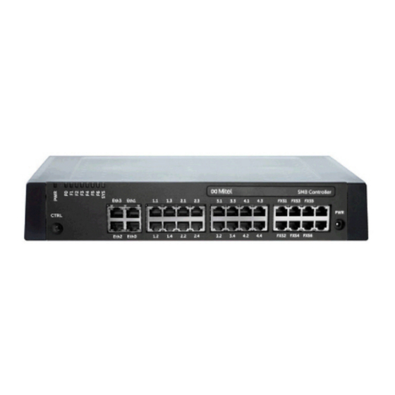
The Mitel SMB Controller, loaded with the MiVoice Office 400 application software, is a communication server in the middle end of the MiVoice Office 400 family in terms of system capacity and expansion possibilities. However all MiVoice Office 400 communication servers are equipped with the same system software and offer the full scope of performance. -
Page 14: Installation Versions
Controller ships with a fitted CPU module, 6 analogue terminal interfaces and 4 Gbit-LAN connections. 2.2.1 Installation versions The Mitel SMB Controller is suitable for both desktop installation, wall mounting and installation in a 19" rack. Covers for connecting cables and special installation covers for rack installation are available separately. -
Page 15: Positioning
The following networking types are possible: Mitel Advanced Intelligent Network (AIN) In an AIN several communication servers of the MiVoice Office 400 series can be connected up to form a homogeneous communication system. The single systems are connected with one another via the IP network, thereby forming the nodes of the overall AIN system One node acts as the Master and controls the other (satellite) nodes. - Page 16 Contact synchronization and management (business and Mitel One (listed as Mitel One in personal). the app store) • Simple admin controls. Table 2: Mitel 6900 SIP series SIP phones Product Principal common features Additional model-specific features • Connection for wall mounting •...
- Page 17 • Magnetic keyboard connector operation (speakerphone) • Can be used as auxiliary • Backlit display reception phone (reduced • Up to 3 expansion key functionality) in hospitality modules can be connected environments Release 7.1 System Manual for Mitel SMB Controller...
- Page 18 System Overview Product Principal common features Additional model-specific features • Wall mounting possible Mitel 6930 SIP and Mitel 6940 SIP: • Power over Ethernet • Cordless speech optimized handset • Mobile phone charging point • MobileLink mobile device integration •...
- Page 19 System Overview Table 3: Mitel 6800 SIP series SIP phones Product Principal common features Additional model-specific features • User-friendly registration, Mitel 6863 SIP: configuration and operation • Integrated 10/100 Mbit of system features through Ethernet switch for MiVoice Office 400 connecting a PC integration.
- Page 20 The phones of the Mitel 6700 SIP series (Mitel 6730 SIP, Mitel 6731 SIP, Mitel 6735 SIP , Mitel 6737 SIP , Mitel 6739 SIP, Mitel 6753 SIP, Mitel 6755 SIP and Mitel 6757 SIP) are supported as before (not all system features can b e used).
- Page 21 • Operator groups and agent control • Line keys and calendar functions • Possibility of synchronisation with a Microsoft Exchange server • All the system features can be used Release 7.1 System Manual for Mitel SMB Controller...
- Page 22 • Backlit display • Powered via DSI bus or • Optional Bluetooth module power supply • Can be used as operator • Wall mounting possible console when combined with expansion key module Release 7.1 System Manual for Mitel SMB Controller...
- Page 23 (can be used with Mitel SIP-DECT only). The Mitel 610 DECT, Mitel 620 DECT, Mitel 630 DECT, Office 135/135pro and Office 160pro/Safeguard/ATEX c ordless system phones are supported as before (not all system features can be used). Release 7.1...
-
Page 24: Various Phones, Terminals And Equipment
The Aastra 1910 and Aastra 1930 analogue phones are still supported. Various phones, terminals and equipment Thanks to the use of international standards other clients, terminals and phones, Mitel and third-party, can be connected and operated on the communication server: •... -
Page 25: Solutions
4 to 600 rooms. This solution is also ideally suited for the management of care homes and retirement homes. The functions are operated using the Mitel 6940 SIP, Mitel 6873 SIP, MiVoice 5380 reception phone or the web-based Mitel 400 Hospitality Manager application. Reduced hospitality functionality are also available on Mitel 6920 SIP, Mitel 6930 SIP, Mitel 6867 SIP and Mitel 6869 SIP phones. -
Page 26: Mitel Applications
Integration in Outlook, Lync 2013 and Office • Search in directories • Compatibility with MiVoice 5300, MiVoice 5300 IP, Mitel 6800/6900 SIP, Mitel 600 DECT series phones • Installation via SSP or WebAdmin • Click to call support (e.g. for Hospitality... - Page 27 Mitel 400 CCS • Mitel 400 CCS is an additional application for the Mitel 400 Call Center, and provides statistics / reporting functions and agent monitoring (CCS = call centre supervision). The licensing of the application is made via OIP.
- Page 28 How to deploy such a solution refer to the document “Mitel SIP Teleworker via MBG on MiVoice Office 400”. Release 7.1 System Manual for Mitel SMB Controller...
- Page 29 The alarm can be set off via a nurse call or fire-alarm system (ESPA interface), via a key predefined on the Mitel DECT or system phone, an alert button, web client, or by calling the alarm server (audio guide), or via e-mail (subject line analysis).
-
Page 30: Application Interfaces
No installation necessary 2.7.2 Application interfaces The most important interface for own and third-party applications is the interface of the Mitel Open Interfaces Platform (OIP). This open interface allows the applications to be deeply integrated with Release 7.1 System Manual for Mitel SMB Controller... - Page 31 System Overview telephony. Third-party applications can also be integrated on MiVoice Office 400 series systems via different interfaces without OIP. 2.7.2.1 Mitel Open Interfaces Platform Figure 3: OIP as middleware between communications system, external data sources and applications OIP services The OIP services are the central components of OIP.
- Page 32 OIP as call center The powerful Mitel 400 Call Center is an integral part of OIP and provides all the main features such as flexible routing algorithms (cyclical, linear, longest time available, CLIP-based, last agent), skill-based agent groups as well as an analysis of the call centre data (online and offline) with chart-based evaluation.
- Page 33 The Mitel Alarm Server is a flexible solution which can be used in all sectors to process and record alarms. It can be used, for instance, in old people's nursing homes and assisted-living homes, as well as in other different facilities such as hotels, industrial plants, shopping centres, schools or administrations.
- Page 34 Client. A first-party CTI solution is ideal for a small number of CTI workstations and is easily implemented. MiVoice Office 400 supports First-Party CTI on all system phones via the Ethernet interface. For some applications, the First-Party TAPI Service Provider (AIF-TSP) is required. Other applications (e.g. Mitel Dialer) use the CSTA protocol.
- Page 35 Configuration is done through WebAdmin. The Mitel 6940 SIP, Mitel 6873 SIP, MiVoice 5380 / 5380 IP reception phone or the web- based Mitel 400 Hospitality Manager application is available to operate the functions. Reduced hospitality functionality are also available on Mitel 6920 SIP, Mitel 6930 SIP, Mitel 6867 SIP and Mitel 6869 SIP phones.
-
Page 36: Getting Started
2.7.3 Getting started If you are setting up an MiVoice Office 400 communication system for the first time, it may be useful to set up a test system step by step on site. After working through the following chapters you can make internal calls between the different types of phones connected to the server. - Page 37 2.7.3.2 Plan and order Set up your MiVoice Office 400 project in Mitel CPQ first. As a result, you will obtain a list of needed components, a slot usage layout, a DSP configuration table and a licence overview. Mitel CPQ is designed to support you with the different activities in the sales and ordering process. It is a web-based application for online usage.
- Page 38 System Overview Ensure that the Mitel SMBC is disconnected from the power supply. Remove the housing cover. Connect the earthing wire on the ground terminal of the bottom plate. Assemble interface cards (if any): • Fit interface cards into the IC1...IC4 slots.
- Page 39 Update the SMB Controller system software Note: If there is already a MiVoice Office 400 application software installed, it might be necessary to install a new version of the same, after an update of the SMB Controller system software. Release 7.1...
- Page 40 Usually this step is only necessary for new installations but may also be necessary after an update of the SMB Controller system software. Be sure to save the MiVoice Office 400 configuration data if there was already a MiVoice Office 400 application software installed.
- Page 41 A first start is executed to set the sales channel and the country specific settings.The Software update view is displayed. As you already have loaded the newest MiVoice Office 400 application software with the SMB Controller Manager you can skip this step.
- Page 42 For Mitel SMBC, the settings have to be done via the SMBC Manager (Linux). Note: If the parameters are not correct, you cannot load audio guides or update Mitel SIP phone strings from the Mitel download server. Click Apply and Next.
- Page 43 Note: Mitel SIP phones get their time and date from an NTP server. To ensure this, check the correct settings in SMBC Manager / Configuration / Date and Time . Register a Mitel SIP phone Go to Terminals / Standard terminals in WebAdmin and click the phone you want to register with the communication server.
- Page 44 Restart the phone. The phone searches for the communication server. If more than one communication server is available, the phone lists them in the format lt;XXX–MAC address>. Choose your communication server from the list, and when prompted, enter the Registration user name and the Registration password.
-
Page 45: Expansion Stages And System Capacity
Mitel CPQ. This is transition session. Summary The expansion possibilities of the basic systems Mitel SMB Controller at a glance. The equipment is powered by an external power supply. The mounting options are described in the Chapter Fitting the communication server. -
Page 46: Basic System
Expansion Stages and System Capacity Basic system The Mitel SMB Controller basic system consists of the following components: • Mainboard with front panel, screw covers and designation label integrated in metal housing with detachable plastic cover • CPU module on mainboard, fitted with a RAM module •... - Page 47 The diagram below shows the position of all the interfaces and slots on the mainboard display and control elements and on the front panel. Only 1 interface (eth0) is usable for MiVoice Office 400 Release 7.1 System Manual for Mitel SMB Controller...
-
Page 48: Power Supply
To ensure that its operation is maintained even in the event of a mains outage, an external uninterruptible power supply (UPS) must be used. For more details about the power supply see Powering the communication server. Release 7.1 System Manual for Mitel SMB Controller... -
Page 49: Media Resources
DTMF receiver for voice mail, auto attendant or analogue terminals Dialling tone receiver Busy tone receiver Ring signal receiver FSK receiver for CLIP detection on analogue network interfaces FSK transmitter for CLIP display on analogue terminals Release 7.1 System Manual for Mitel SMB Controller... - Page 50 VoIP mode parameter is set to G.711. The configured VoIP mode is valid for all the DSP chips of a node. • The system has to be restarted for the configuration changes of the DSP to take effect. Release 7.1 System Manual for Mitel SMB Controller...
-
Page 51: Media Proxy
(CPU module, RAM module). This chapter describes only the system modules that can be expanded as an option. They expand the resources of the communications server, which means the system can be expanded step by step in line with requirements. Release 7.1 System Manual for Mitel SMB Controller... - Page 52 Voice over IP, fax transmissions, audio services or integrated mobile/external phones. This means that for each DSP chip a specific number of channels is available for the corresponding functions. Functions are allocated in WebAdmin in the Media resources view. Release 7.1 System Manual for Mitel SMB Controller...
- Page 53 Announcement service and music on hold use their own resources. Note: On the Mitel SMBC communication server G.711 audio channels are always used for audio services. The Voice mail mode parameter can therefore not be changed for this system.
- Page 54 The figure below gives an overview of the cases where VoIP channels are needed and how many of them. Table 16: Required VoIP channels between two possible endpoints Release 7.1 System Manual for Mitel SMB Controller...
- Page 55 G.729 for coding voice data. Secure G.711 Same as G.711 but with a more The Secure VoIP licence, valid secure data transmission using right across the system is the SRTP protocol. required. Release 7.1 System Manual for Mitel SMB Controller...
- Page 56 Number of audio channels on this node used for auto attendant and queue with announcement only. Reserved for voice mail Number of audio channels on this node that can be used exclusively for voice mail. Release 7.1 System Manual for Mitel SMB Controller...
- Page 57 Table 19: Max. number of channels per DSP chip on SM-DSPX1 or SM-DSPX2 DECT VoIP FoIP Audio Remarks Of relevance only to certain countries such as Brazil Release 7.1 System Manual for Mitel SMB Controller...
- Page 58 G.711/G.729: 6 channels • Secure G.711/G.729: 5 channels Only for VoIP mode = G.711 or G.711/G.729 Only for VoIP mode = G.711 or G.711/G.729 Of relevance only to certain countries such as Brazil Release 7.1 System Manual for Mitel SMB Controller...
-
Page 59: Interface Cards
The interfaces are routed to the front panel using the wiring adapters (see Wiring adapter). The length varies depending on the type of interface card. For precise dimensions see the Chapter Technical data. Figure 6: Design of the interface cards Release 7.1 System Manual for Mitel SMB Controller... -
Page 60: Wiring Adapter
The wiring adapters route the interfaces of the various interface cards with the right connection diagram to the RJ45 sockets on the front panel. The adapters are fitted to WA1...WA4 sockets. Card with hardware version >= "1A" only. Card must not be used in USA/Canada. Release 7.1 System Manual for Mitel SMB Controller... - Page 61 Included in the equipment supplied with the interface card The assignment to the RJ45 sockets depending on the wiring adapters is shown in Combinations of wiring adapters / interface cards. Must not be used in USA/Canada. Release 7.1 System Manual for Mitel SMB Controller...
-
Page 62: System Capacity
IP – IP via SIP access channels (external) Only 1 operator console, 1 MiVoice 2380 IP, 1 Mitel SIP-DECT, 2 DECT-cordless phones and 1 MiCollab client (3 MiCollab clients with MiCollab version 8.1) are possible for each user. Release 7.1... - Page 63 Audio channels can be used for voice mail, auto attendant, queue with announcement, call recording, announcement with audio file, or conference bridge. Announcement service and music on hold use their own resources. Of relevance only to certain countries such as Brazil Release 7.1 System Manual for Mitel SMB Controller...
- Page 64 Members per user group "normal" Members per user group "large" 12 of them are masked (not configurable) In USA/Canada the abbreviation DID (Direct Inward Dial) is used instead of DDI (Direct Dialling In) Release 7.1 System Manual for Mitel SMB Controller...
- Page 65 SIP: 9 keys; Mitel 6869/73 SIP: 12 keys; Mitel 6900 SIP: 12 keys The value applies to CDE with destination KT line. With MiVoice Office 400 multiple destinations (User + KT or KT + UG) the value is reduced to 4.
- Page 66 Allocations of external call numbers to internal call numbers External digit barring Internal digit barring Barred list Free list Predefined text messages Announcement / message groups User per announcement / message group Data service tables Release 7.1 System Manual for Mitel SMB Controller...
- Page 67 Groups, Agents (OIP Call centre) Mailboxes with Basic or Enterprise voice mail system Greetings per mailbox Profiles per mailbox for auto attendant Backup communication servers for Dual Homing Primary communication servers for Dual Homing Blacklist Release 7.1 System Manual for Mitel SMB Controller...
- Page 68 Total call list entries 60000 60000 Configured keys 48000 48000 Busy lamp field keys on Mitel SIP 4000 4000 phones in total Busy lamp field keys per Mitel SIP phone Same users on busy lamp field...
-
Page 69: Terminals
Miscellaneous Free seating pools Terminals on DSI interfaces (total) Digital system MiVoice 5360 phones MiVoice 5361 MiVoice 5370 MiVoice 5380 4 interface cards 8 DSI required Release 7.1 System Manual for Mitel SMB Controller... - Page 70 Maximum 64 radio units per location area if 4 location areas are defined, or maximum 128 radio units per location area if 2 location areas are defined. Operation on 2 DSI interfaces in each case Release 7.1 System Manual for Mitel SMB Controller...
- Page 71 MiVoice 5380 IP IP operator Mitel 6930 SIP consoles / IP operator Mitel 6940 SIP applications Mitel 6869 SIP Mitel 6873 SIP MiVoice 5380 IP MiVoice1560 Reception/Front Mitel 6940 SIP desk Mitel 6873 SIP Release 7.1 System Manual for Mitel SMB Controller...
- Page 72 Mitel SIP-DECT Cordless phones Standard SIP terminals CloudLink Gateway – Virtual terminals – Integrated mobile/external phones – Mitel One BRI-S Terminals on BRI-S interfaces (total) Refer CloudLink Gateway document Maximum of 2 simultaneous call connections. Release 7.1 System Manual for Mitel SMB Controller...
- Page 73 External switches for controlling internal switch groups via control inputs General bell 1 per node Transmission with the T.38 protocol is recommended for Fax over IP. The corresponding media resources need to be allocated. Release 7.1 System Manual for Mitel SMB Controller...
-
Page 74: Terminal And Network Interfaces
SIP access channels 3.4.4 Software assurance Software Assurance (SWA) is Mitel’s comprehensive support offer which gives access to new software releases, support services and SRM remote access to the communication server. In maximum expansion network access is possible only via IP Release 7.1... -
Page 75: Licences
3.4.5 Licences Use of the call manager software requires a licence. The Mitel CPQ application automatically plans the necessary licences, which are then enabled on the communication server using a licence file. The licence file contains all the enabled licences. When you purchase a new licence from your authorised dealer, you obtain a new licence file in return. - Page 76 User • Users Mitel SMBC requires a User or an IP User licence for each user in the system. Exception: A user without a terminal or with a virtual terminal only does not need a licence. • User A user with such a normal user license can have up to eight terminals of the type: Analogue, ISDN, DSI, DECT, SIP-DECT.
- Page 77 If the required licences are missing, the relevant event message is output on the system. • Mitel SIP Terminals To operate Mitel SIP terminals of the Mitel 6800/6900 SIP series, the user requires an IP user licence. • Mitel One With this licence, a mobile phone with the Mitel One application can be integrated into the communication system together.
- Page 78 • Conference Bridge (Dial-In conference) This licence is included in the MiVoice Office 400 SMBC Base kit - S bundle and allows the use of a conference bridge. The internal or external conference participants choose a specific call number and are connected with the conference after entering a PIN.
- Page 79 SIP Access Channels The connection of the system to a SIP service provider or the networking of the systems via SIP requires one licence per channel. The MiVoice Office 400 SMBC Base kit - S bundle includes these SIP access channel licenses Release 7.1...
- Page 80 It cannot be combined with CTI third-party licences. • Dialers This licence allows you to use the Mitel Dialer CTI application. The number of licences determines the simultaneously active, user-assigned Mitel Dialer applications. • Hospitality Bundle SMBC / VA - S This bundle allows you to use the Mitel 400 Hospitality Manager.
-
Page 81: Restricted Operating Mode
• ATAS Interface / ATASpro Interface These licenses are included in the MiVoice Office 400 SMBC Base kit - S bundle and allows to connect external alarm and messaging sources via the Ethernet interface. ATAS Interface: Many commands available for messaging (displaying text and presenting softkeys on system phones), emergency number called alarm, safeguard basic with Redkey, charging bay monitoring etc. -
Page 82: Temporary Offline Licences
4 hours after the new software has been uploaded or after a restart operation, the communication server switches over to a restricted operating mode (see Restricted operating mode). Release 7.1 System Manual for Mitel SMB Controller... - Page 83 8 phone licences (any one) • 8 phones per user • Video licence for all licensed phones. • MiCollab role UCC Entry. • 1 MiVoice Office Mitel One client license per user Release 7.1 System Manual for Mitel SMB Controller...
- Page 84 8 phone licences (any one) • 8 phones per user • Video licence for all licensed phones. • MiCollab role UCC Premium • 1 MiVoice Office Mitel One client license per user Features Release 7.1 System Manual for Mitel SMB Controller...
- Page 85 If VoIP mode is set to G.711, two G.711 VoIP channels per system can be used without a licence. If Virtual Appliance is used as Master, the VoIP channels of the master node are made available without a licence from the integrated Mitel Media Server. However, for the satellites' VoIP channels, the licences must be purchased. Release 7.1...
- Page 86 CSTA protocol. licence node. OAI Interface Use of the Open Locked Enabled In the AIN, only – Application on the Master; Interface otherwise per node. Release 7.1 System Manual for Mitel SMB Controller...
-
Page 87: Power Supply Capacity
Wire diameter: 0.5 mm • Line length: 200 m The table below shows the average power requirements of the terminals for a line length of approx. 200 m and a wire diameter of 0.5 mm. Release 7.1 System Manual for Mitel SMB Controller... - Page 88 The value applies to each interface and to radio units with hardware version “-2”. The value per interface for radio units with hardware version “-1” is 150 mW lower. The value depends greatly on the terminal type. Release 7.1 System Manual for Mitel SMB Controller...
-
Page 89: Power Supply Per Terminal Interface
Terminals Socket Output P [mW] Analogue terminals FXS interface approx. 500 3.5.2 Power supply per terminal interface The power supply per terminal interface is determined by the interface type. The interface load depends on the following variables: • Terminals used incl. auxiliary devices •... -
Page 90: Installation
Finally the chapter also describes the network and terminal-side connection of the interfaces and the installation, powering and connection of system terminals. System components The figure below shows the components of the Mitel SMB Controller complete with mounting options. Figure 8: System components with mounting options Release 7.1... -
Page 91: Fitting The Communication Server
4.2.2 Mounting options Mitel SMBC includes all the materials required for wall or desktop installation. Additional rack installation sets are required for a 19” rack installation. For wall mounting all the connecting cables can be concealed behind a cable cover. This set can be ordered as an option. -
Page 92: Safety Regulations
19” rack must remain empty. Environment • Ambient temperature 5 °C...45 °C • Relative humidity 30…80%, non-condensing 4.2.4 Safety regulations Be sure to observe the following safety regulations before carrying out work inside a communication server: Release 7.1 System Manual for Mitel SMB Controller... -
Page 93: Wall Mounting
Maintaining minimum distances also allows the installation of the cable cover and the possibility of suspending the communication server into and out of the wall-mounted screws. The two diagrams below illustrate the two wall-mounting possibilities. Release 7.1 System Manual for Mitel SMB Controller... - Page 94 Depending on the type of mounting, these are the suspension points marked under position A or B on the drilling plan. The communication server is secured with a third screw to prevent it from being dislodged accidentally (position C). Release 7.1 System Manual for Mitel SMB Controller...
- Page 95 The packaging box of the communication server can also be used for marking out the drill holes. To do so it is best to detach the part of the inner packaging box that contains the drill holes. Note: The holes on the cardboard box are not labelled. Release 7.1 System Manual for Mitel SMB Controller...
- Page 96 Screw in the two shorter upper dowel screws (position A or B). Observe the distance between the screw heads and the wall as shown in Drilling plan for wall mounting. Shut down the communication server (see Shut-down mode) and disconnect it from the power supply. Release 7.1 System Manual for Mitel SMB Controller...
-
Page 97: Rack-Mounting
The space on the left and right between the communication server and the panels of the 19” rack is for heat dissipation and must remain clear. • With interface cards with more than 8 ports it is advisable to route the cabling via an fan-out-panel (FOP) (1 height unit). Release 7.1 System Manual for Mitel SMB Controller... - Page 98 Shut down the communication server (see Shut-down mode) and disconnect it from the power supply. CAUTION: Be sure to observe the Safety regulations. Remove the housing cover. Release 7.1 System Manual for Mitel SMB Controller...
-
Page 99: Desktop Installation
To protect the cable connections the communication server can also be secured using three screws. The same drilling plan (see Drilling plan on page 88) and the same procedure apply as for wall mounting (see Wall-mounting procedure). Release 7.1 System Manual for Mitel SMB Controller... -
Page 100: Powering The Communication Server
20 A maximum in countries with 115 V mains power (e.g. in North America). Please also note the following points: • The mains connector acts as a disconnecting device and must be positioned so that it is easily accessible. Release 7.1 System Manual for Mitel SMB Controller... -
Page 101: Uninterruptible Power Supply (Ups)
60% of the maximum power requirements is needed. Note: The uninterrupted operation of the communication server is ensured if the UPS takes over the power supply within 20ms of the mains outage. See also Release 7.1 System Manual for Mitel SMB Controller... -
Page 102: Earthing And Protecting The Communication Server
The serrated lock washer must rest against the metal housing of the communication server. Figure 16: Earthing connection Release 7.1 System Manual for Mitel SMB Controller... - Page 103 Installation Figure 17: Earthing of the communication server in the case of an indirect cabling and direct cabling Release 7.1 System Manual for Mitel SMB Controller...
-
Page 104: Connecting The Cable Screening
Note: Connect the cable screens to one another at the splitting point only. Observe the tree structure principle to prevent earth loops. Figure 18: Tree structure principle Release 7.1 System Manual for Mitel SMB Controller... -
Page 105: Equipping The Basic System
Wiring adapters are used to route the interfaces of the interface cards to the RJ45 sockets on the front panel and are fitted to slots WA1…WA4. (see also Interfaces, display and control elements on page 40). Release 7.1 System Manual for Mitel SMB Controller... - Page 106 – The wiring adapter is not part of the equipment supplied with this interface card and must be ordered separately. Must not be used in USA/Canada. Not yet supported with Release 6.0 Release 7.1 System Manual for Mitel SMB Controller...
-
Page 107: Fitting Dsp Modules
For test purposes the PRI interface is also routed in parallel to port X.2. Must only be used in USA/Canada. Port 7 is also routed to X.3 Port 8 is also routed to X.4 Release 7.1 System Manual for Mitel SMB Controller... -
Page 108: Component Mounting Rules
Indirect cabling via (main) distribution frame and any universal building cable installation (UBC) (see also Connecting to a UBC via a (main) distribution board (example) Connecting to a UBC via wiring centre (example)). Figure 20: Direct cabling (left) and indirect cabling (right) Release 7.1 System Manual for Mitel SMB Controller... -
Page 109: Direct Connection
The interface sockets on the front panel and on the fan-out-panel (FOP) where applicable are connected with the (main) distribution frame or the patch panels using either patch cables or prefabricated system cables (see Equipment Overview). Release 7.1 System Manual for Mitel SMB Controller... - Page 110 With terminal cards with 8 or more interfaces, some or all of the RJ45 sockets are assigned four-fold on the front panel of the Mitel SMBC. With this cable they can be connected without the use of a fan-out-panel (FOP). The cable is 6 m long and at one extremity has four RJ45 connectors on which all the pins are wired.
- Page 111 Two-wire connection violet x.2b white x.3a brown x.3b turquoise x.4a violet x.4b white x.1a grey x.1b turquoise x.2a violet x.2b x.3a blue x.3b turquoise x.4a violet x.4b x.1a orange x.1b Release 7.1 System Manual for Mitel SMB Controller...
- Page 112 10 terminal interfaces (DSI, FXS) or a combination thereof. Note: This cable cannot be used to connect PRI and Ethernet interfaces (see also Connection of PRI primary rate interface Connection of Ethernet interfaces). Not valid for USA/Canada. Release 7.1 System Manual for Mitel SMB Controller...
- Page 113 Table 32: Schematic diagram of prefabricated system cable 12 x RJ45 Stranded Core colour Cable RJ45 Signal element designation Connection Two-wire four-wire connection white blue turquoise – violet – white orange turquoise – violet – white – green – turquoise – Release 7.1 System Manual for Mitel SMB Controller...
- Page 114 Connection Two-wire four-wire connection violet – white – brown – turquoise – violet – white – grey – turquoise – violet – – blue – turquoise – violet – – orange – Release 7.1 System Manual for Mitel SMB Controller...
- Page 115 – 4.6.2.2 Connection to a universal building cable installation (UBC) Figure 22: Connecting to a UBC via a (main) distribution board (example) Figure 23: Connecting to a UBC via wiring centre (example) Release 7.1 System Manual for Mitel SMB Controller...
-
Page 116: Cabling Interfaces
Cabling interfaces All the interfaces are routed to the front panel and are therefore accessible without opening the communication server. Figure 24: Interfaces on the front panel with port designation (Mitel SMBC) 4.7.1 Port addressing A port address is always of the type x.y. (x is the number of the card slot, and y, the port number.) -
Page 117: Network Interfaces
Equipping the system with interface cards provides the necessary network interfaces. With the exception of the Ethernet interface, which also represents a network interface via SIP access, there are no network interfaces on the Mitel SMBC mainboard. 4.7.2.1 Basic rate interface BRI-T With the appropriate interface cards and wiring adapters, BRI network interfaces can be made available at RJ45 sockets 1.x...4.x.The possible RJ45 sockets are highlighted in colour in the figure below. - Page 118 Figure 26: Basic access on NT1 Do not connect power supply NT1 Do not fit the jumper The assignment of the RJ45 connector is identical on the NT-side and on the side of the communication server. Release 7.1 System Manual for Mitel SMB Controller...
- Page 119 Figure 27: BRI-S basic rate interface external, networked with copper line Table 36: Connection of BRI-S basic rate interface external, networked with copper line PINX 1 signal Basic access Cable cores PINX 2 signal, Basic rate BRI-S ext. interface BRI-T Release 7.1 System Manual for Mitel SMB Controller...
- Page 120 Table 37: Cabling for basic rate interface BRI-T, networked with leased-line or dial-up connection PINX1 signal, Cable cores Network Cable cores PINX 2 signal, basic rate basic rate interface BRI- interface BRI- See also Chapter "Connections with basic accesses" in the PISN/QSIG Networking System Manual. Release 7.1 System Manual for Mitel SMB Controller...
- Page 121 The connection to NT1 (Network Termination) is implemented using commercially available screened cables with 8-pin RJ45 connectors at both ends, e.g. S-FTP 4P, PVC, Cat. 5e. TIC-1PRI not for USA/Canada, TIC-1PRI-T1 only for USA/Canada. Release 7.1 System Manual for Mitel SMB Controller...
- Page 122 Cable cores Straight Communication server patch cable Socket PRI signal Socket PRI signal Other designations are also possible on the NT1 such as: "S2m ab" instead of "TxA/TxB" and "S2m an" instead of "RxA/RxB". Release 7.1 System Manual for Mitel SMB Controller...
- Page 123 Cable cores Straight Communication server patch cable – – – – – – – – 4.7.2.2.3 Primary rate access in the private leased-line network Figure 31: Primary rate access, networked with copper line Release 7.1 System Manual for Mitel SMB Controller...
- Page 124 RJ45Pin PRI PINX 1 Cable cores Crossed PRI PINX 2 signal RJ45Pin signal patch cable — — — — — — — — Figure 32: Primary rate interface, networked with transmission equipment Release 7.1 System Manual for Mitel SMB Controller...
- Page 125 Straight PINX 2 signal straight signal patch cable signal patch cable — — — — — — — — Figure 33: Primary rate access PRI, networked with leased-line or dial-up connection Release 7.1 System Manual for Mitel SMB Controller...
- Page 126 On cards with 16 interfaces RJ45 sockets 9 to 16 are multiply assigned. The signals can be split again to individual RJ45 sockets using patch cables and the fan-out panel FOP (see Fan-out panel FOP) or with 8- fold assigned connecting cables (see e.g. Prefabricated system cable 4 x RJ45). Release 7.1 System Manual for Mitel SMB Controller...
- Page 127 25 mA, which does not cause any restrictions. • Circuit type as per EN/IEC 60950: TNV-3 4.7.2.3.1 Connection Assignment of the RJ45 sockets on the front panel: Release 7.1 System Manual for Mitel SMB Controller...
- Page 128 – – – – – Table 44: Connection of four-fold assigned FXO network interface Public analogue network Splitting with fan-out panel FOP or 8-fold assigned Communication connecting cables server FXO signal Socket Release 7.1 System Manual for Mitel SMB Controller...
- Page 129 Installation 4.7.2.3.2 Cable Requirements Table 45: Cable requirements for FXO network interface Core pairs X cores 1 X 2 Release 7.1 System Manual for Mitel SMB Controller...
-
Page 130: Terminal Interfaces
Prefabricated system cable 4 x RJ45).The possible RJ45 sockets are highlighted in colour in the figure below. Figure 36: Connection possibilities for DSI terminal interfaces on multiply assigned RJ45 sockets Not yet supported with Release 6.0 Release 7.1 System Manual for Mitel SMB Controller... - Page 131 Connection Table 46: Connection of individually assigned DSI terminal interface Communication server Cable Connection socket cores Socket DSI signal DSI signal Socket – – – – – – – – – – Release 7.1 System Manual for Mitel SMB Controller...
- Page 132 Socket – – Table 47: Connection of four-fold assigned DSI terminal interface Communication server Splitting with Connection socket fan-out panel FOP or 8- fold assigned connecting cables Socket DSI signal Socket signal Release 7.1 System Manual for Mitel SMB Controller...
- Page 133 Installation Communication server Splitting with Connection socket fan-out panel FOP or 8- fold assigned connecting cables Socket DSI signal Socket signal Release 7.1 System Manual for Mitel SMB Controller...
- Page 134 Total length of DSI-AD2 bus Distance between the 1st and 2nd connection point (without connection cable) A: max. 1200 m – B: max. 1200 m C: max. 10 m Figure 37: DSI-AD2 bus Release 7.1 System Manual for Mitel SMB Controller...
- Page 135 Radio units: Active call connection on all channels Although no longer available, the phone is still supported. The value can increase to approx. 600 mW if the power available at the DSI-AD2 bus allows it. Release 7.1 System Manual for Mitel SMB Controller...
- Page 136 The value applies to radio units with hardware version “-2”. The value for hardware version “-1” is 300 mW lower. The value applies to each interface and to radio units with hardware version “-2”. The value per interface for radio units with hardware version “-1” is 150 mW lower. Release 7.1 System Manual for Mitel SMB Controller...
- Page 137 Installation Figure 38: Power available case A on the DSI-AD2 bus Power available case B: Figure 39: Power available case B on the DSI-AD2 bus Release 7.1 System Manual for Mitel SMB Controller...
- Page 138 Power available case A on the DSI-AD2 bus indicates: • Maximum line length for a wire diameter of 0,4 mm: 840 m • Maximum line length for a wire diameter of 0,5 mm: 1200 m Release 7.1 System Manual for Mitel SMB Controller...
- Page 139 130 W (1 MHz) 4.7.3.1.2 Installation rules • If a Mitel DECT radio unit is used, do not connect any other system phone to the same DSI bus. • Do not use any terminating resistors at the bus extremity. •...
- Page 140 BRI-S terminal interfaces Figure 40: Connection possibilities for BRI-S terminal interfaces Note: Some of the interfaces can be configured on BRI-T using the wiring adapters (see Fitting a wiring adapter). Applies in Australia only Release 7.1 System Manual for Mitel SMB Controller...
- Page 141 The S bus is a four-wire, serial ISDN bus based on the DSS1 protocol (ETSI standard). It starts in each case at an BRI-S interface of the communication server. Four bus configurations are possible, depending on the line length and the number of terminals: Release 7.1 System Manual for Mitel SMB Controller...
- Page 142 The maximum number of terminals per S bus depends on the power requirements of the terminals (see Restrictions). Figure 41: S bus, short Figure 42: S bus, short, V-shaped Figure 43: S bus, long Release 7.1 System Manual for Mitel SMB Controller...
- Page 143 The number of terminals is the sum of the power requirements of the individual terminals and the power available on the S bus. 4.7.3.2.3 Connection sockets Figure 45: RJ45 connection, single socket These values are based on a wire diameter of 0.5 mm. Release 7.1 System Manual for Mitel SMB Controller...
- Page 144 Installation Figure 46: RJ45 connection, double socket 4.7.3.2.4 Installation rules Note: Circuit type as per EN/IEC 60950: SELV Always terminate the bus extremity with 2 ´ 100 W (0.25 W, 5%)! Release 7.1 System Manual for Mitel SMB Controller...
- Page 145 FXS terminal interfaces can also be made available at the RJ45 sockets 1.x...4.x. The possible RJ45 sockets are highlighted in colour in the figure below. Figure 47: Connection possibilities for FXS terminal interfaces Not possible within an AIN Release 7.1 System Manual for Mitel SMB Controller...
- Page 146 Ports for switching external equipment. Ports for switching internal switch groups. Control input General bell Commercial auxiliary bells After a first start all the FXS interfaces are configured on Phone / Fax. Release 7.1 System Manual for Mitel SMB Controller...
- Page 147 53 VDC. The loop current is limited to 25 mA on all ports. Transmission with the T.38 protocol is recommended for Fax over IP. The corresponding media resources need to be allocated. Release 7.1 System Manual for Mitel SMB Controller...
- Page 148 FXS mode: 2-wire door In this mode 2-wire door intercoms with DTMF control functions can be connected. The no-load voltage in this mode is 24 VDC. The loop current is limited to 25 mA. Release 7.1 System Manual for Mitel SMB Controller...
- Page 149 (announcement prior to answering), voice mail greetings or for "Music on hold" and then to store it as a wave file. Figure 51: Connection for FXS mode: External audio source Release 7.1 System Manual for Mitel SMB Controller...
- Page 150 The customer is responsible for all copyright matters relating to any music playback. Table 58: Technical data for FXS mode: External audio source Input impedance approx. 15 kW Input level not configurable Input circuit asymmetrical Output resistance audio source 1 kW Release 7.1 System Manual for Mitel SMB Controller...
- Page 151 [1] The diode is necessary, in order to avoid unwanted voltages at the control output during the the start-up phase of the communication server. Figure 53: Connection for FXS mode: Control output Release 7.1 System Manual for Mitel SMB Controller...
- Page 152 Table 59: Switch group control via the control inputs FXS control input 1 FXS control input 2 Switch positions of the switch group Position 1 Position 2 Release 7.1 System Manual for Mitel SMB Controller...
-
Page 153: Fan-Out Panel Fop
The fan-out panel (FOP) takes up the space of one height unit in a rack and can be fitted directly above or below the communication server. Figure 56: Front panel, FOP fan-out-panel Release 7.1 System Manual for Mitel SMB Controller... - Page 154 (FOP) strip using 2 patch cables. Figure 57: Connection of four-fold assigned sockets via FOP connector strip The patch cables are available separately in lengths of 1 and 2 m (see Equipment Overview). Release 7.1 System Manual for Mitel SMB Controller...
- Page 155 Installation The internal wiring of the fan-out panel is shown in the table below. The wiring is shown for sockets 1 - 4. Sockets 5 - 8 are wired accordingly. Release 7.1 System Manual for Mitel SMB Controller...
- Page 156 Installation Table 60: Wiring of sockets 1–4 in the fan-out panel FOP Fan-out panel FOP Internal Fan-out panel FOP wiring Socket Signal Signal Socket Socket Release 7.1 System Manual for Mitel SMB Controller...
-
Page 157: Ethernet Interfaces
4.7.5 Ethernet interfaces The Mitel SMBC communication server has 4 GByte Ethernet interfaces permanently routed to the front panel and labelled accordingly. The RJ45 sockets are highlighted in colour in the figure below. Figure 58: Connection possibilities for Ethernet interfaces 4.7.5.1... - Page 158 Gateway IP address of the default gateway. For example: 192.168.104.1 MTU stands for Maximum Transaction Unit. It is defined as the maximum size of each packet transmitted in a single network transaction. Release 7.1 System Manual for Mitel SMB Controller...
- Page 159 You can program Static IP routes, which belong to the network interface (eth0) interface. Table 64: Static routes for eth0 Parameter Parameter value Description Free text that is used for static routes. IP address IP address of the static route. Release 7.1 System Manual for Mitel SMB Controller...
- Page 160 The Ethernet interfaces routed to the front panel can be configured individually in the network view of the SMB Controller Manager. Status LED The status of the Ethernet interface LAN1 is indicated on the LED display panel. Release 7.1 System Manual for Mitel SMB Controller...
- Page 161 Port is receiving or sending data 1 Gbit/s Port has a connection with the network Flashing 10/100 Mbit/s Port is receiving or sending data 10/100 Mbit/s Port has a connection with the network Release 7.1 System Manual for Mitel SMB Controller...
- Page 162 Core pairs x cores 2 x 2 (short distances also 1 x 4) Core pairs x cores 4 x 2 Core pairs x cores 4 x 2 Stranded Wire diameter, core 0.4...0.6 mm Screening Release 7.1 System Manual for Mitel SMB Controller...
-
Page 163: Multi-Gateways For Sip Trunks
IP address of the subnet or the ethernet interface is used as a source address. The packages that MiVoice Office 400 uses has a source address and an appropriate IP address that is specified for the subnet. These are sent to the gateway of the subnet or the ethernet interface. -
Page 164: Installing, Powering, Connecting And Registering Terminals
Installing, powering, connecting and registering terminals IP system phones Accesses Table 68: Socket connections of the IP system phones of the MiVoice 5300 IP series PoE Ethernet interface for connection to the IP network Release 7.1 System Manual for Mitel SMB Controller... - Page 165 Power supply If your network supports Power-over-Ethernet, the IP system phone is powered directly via the LAN connection and there is no need to connect the power supply available as an option. Release 7.1 System Manual for Mitel SMB Controller...
- Page 166 PSE (Power Source Equipment) = power supply device, e.g. a switch PD (Powered Device) = power consumer, e.g. an IP system phone including an MiVoice M530 or MiVoice M535 expansion keypad including up to three MiVoice M530 or MiVoice M535 expansion keypads Release 7.1 System Manual for Mitel SMB Controller...
-
Page 167: Mitel 6800/6900 Sip Phone Series
Installation 15.4 W 6.49...12.95 W You can obtain information on how to operate and register the IP system phones on a MiVoice Office 400 communication server in the WebAdmin online help. 4.8.1 Mitel 6800/6900 SIP phone series Mitel SIP phones are platform-independent phones with a wide range of features. They can also be perfectly integrated into one of the Mitel Platforms and used as a system phone. - Page 168 Two system phones can be connected to a DSI interface (DSI-AD2 only). The system can only differentiate the two system phones by the position of the address switch on the phone. The following settings are possible (TSD = Terminal Selection Digit): • TSD1 • TSD2 Release 7.1 System Manual for Mitel SMB Controller...
- Page 169 Carrying out a logon on the system phone: Long keypress (long click) on a function key. Set new phone type appears next. Confirm with Foxkey Yes. 4.8.5.1 Digital system phones General information Accesses Release 7.1 System Manual for Mitel SMB Controller...
- Page 170 Two system phones can be connected to a DSI interface (DSI-AD2 only). The system can only differentiate the two system phones by the position of the address switch on the phone. The following settings are possible (TSD = Terminal Selection Digit): • TSD1 • TSD2 Release 7.1 System Manual for Mitel SMB Controller...
- Page 171 MiVoice 5361 / 5370/ 5380 These IP system phones can be both desktop-mounted and wall-mounted. Mounting the phone The following points are described in detail in the User’s Guides for MiVoice 5361 / 5370 / 5380: Release 7.1 System Manual for Mitel SMB Controller...
-
Page 172: Dect Radio Units And Cordless Phones
DECT radio units and cordless phones The locations determined for the cordless phones, charging bays and radio units during the planning phase need to be checked against the following criteria: • Influence on radio operation Release 7.1 System Manual for Mitel SMB Controller... - Page 173 Do not remove the cover of the radio unit. (Warranty protection will lapse if the cover is removed) Fit the mounting bracket (see Dimensional drawing for wall-mounting the mounting bracket dimensional drawing for wall mounting). Observe the minimum distances (see Installation distances). Release 7.1 System Manual for Mitel SMB Controller...
- Page 174 [1] X = 200: Minimum distance if the radio units are connected to the same communication server (synchronous) X = 2000: Minimum distance if the radio units are not connected to the same communication server (not synchronous) Release 7.1 System Manual for Mitel SMB Controller...
- Page 175 Installation Make sure the minimum distances are observed Connecting the radio unit Figure 63: Underside of the radio units with connection points Table 73: Connections on the Mitel DECT radio units RJ12 sockets Socket 1: DSI interface Socket 2: Power...
-
Page 176: Analogue Phones Mitel 6710 Analogue, Mitel 6730 Analogue
As the DECT systems of the individual nodes in an AIN do not run synchronously, the two DSI interfaces of an SB-8 / SB-8ANT must always be connected to the same node. Table 74: Operating state display on Mitel DECT radio units LED flashing (two LEDs on the SB-8) - Page 177 Tip for the setting polarity reversal: Set the switch of the phone (e. g. Mitel 6730 Analogue) to the symbol "−". If the MWI LED is blinking when a message is available and off when no message is available, the switch is set correctly. If the MWI LED is on when a message is available and blinking when no message is available the switch must be set to “+”.
- Page 178 If not, you can load the key configuration on the phone after connecting the phone, by clicking Update key configuration on phone. To load the key configuration on all connected Mitel 6700 Analogue series phones, click Update key configuration for all Mitel 6700 Analogue phones.
-
Page 179: Configuration
A context-sensitive online help provides valuable instructions on configuration, and step-by-step instructions. The chapter ends with valuable information and instructions on how to configure your MiVoice Office 400 communication system. SMB Controller Manager This web-based configuration tool is available for all Mitel SMB Controller, independent of a loaded call manager or other software application. -
Page 180: Network Interfaces For Sip Trunk
WebAdmin Configuration Tool This web-based configuration tool is available for the online configuration of MiVoice Office 400 series communication servers. It offers a simple, user-friendly interface and an online help, and with its different authorization levels it is aimed at different user groups: Release 7.1... - Page 181 The Hospitality Administrator features all the views required to set up the Mitel 400 Hospitality Manager and the reception menu of the Mitel 6940 SIP, Mitel 6873 SIP or MiVoice 5380 / 5380 IP and specify its default settings. A link can also be used to start the Mitel 400 Hospitality Manager (see...
-
Page 182: Integrated And Auxiliary Applications
Integrated and auxiliary applications Mitel 400 Hospitality Manager The Mitel 400 Hospitality Manager is a web-based application for receptionists in the hospitality sector. It provides a clear, at-a-glance list view or floor-by-floor view of the rooms and features functions such as check-in, check-out, notification, wake-up call, retrieval of call charges, maintenance list, etc. - Page 183 Access:You can access a user's Self Service Portal by entering any of the following combinations (registration data) on the WebAdmin registration page: • Call number + PIN • Windows user name + PIN Release 7.1 System Manual for Mitel SMB Controller...
-
Page 184: Access Types With Smb Controller Manager
PC. If this is not the case, you can also connect the computer directly to the communication server using a LAN cable. See also: If the IP address of your communication server is not known or if your are setting up an MiVoice Office 400 communication system for the first time, read the chapter Getting started). -
Page 185: User Access Control
(access data). We have to distinguish between the user access via SMB Controller Manager and the user access via WebAdmin to the MiVoice Office 400 communication server. 5.5.1 SMB Controller Manager user accounts For the SMB Controller Manager there are two default user accounts. -
Page 186: Webadmin User Accounts And Authorization Profiles
To access the default user account (Default User Account) enter the following: Table 78: Standard user account and standard password User name admin Password After first start, you are asked to enter and confirm a new password for the admin account. Release 7.1 System Manual for Mitel SMB Controller... - Page 187 For password selection and input, see Password syntax. Other predefined user accounts Furthermore there are predefined user accounts for the Mitel Dialer for MiCollab, for OpenMobilityManager (OMM), and for CloudLink gateway. You can see the predefined user accounts in the User account view. Note: The predefined user accounts cannot be deleted.
- Page 188 For user account, after a maximum of 15 unsuccessful logins, the account is disabled for 10 minutes. The account is automatically re-enabled after 10 minutes. The account does not require administrator to re- enable. Release 7.1 System Manual for Mitel SMB Controller...
-
Page 189: Automatic Exit From The Configuration
Each access attempt generates an entry in the corresponding list. In case of remote maintenance an entry will not be generated if remote maintenance is barred or if CLIP required is activated in the configuration and no CLIP is received. Release 7.1 System Manual for Mitel SMB Controller... -
Page 190: Webadmin Remote Access
The authorisation to activate or bar remote maintenance access using the function code is defined and granted to the user with the parameter Remote maintenance access in a permission set. After a first start of the communication server, the authorizations of all users are restricted. Release 7.1 System Manual for Mitel SMB Controller... -
Page 191: Function Code For Remote Maintenance Access
In an AIN the remote maintenance access of all the nodes depends on the setting in the Master. If remote maintenance access is enabled in the Master, both the AIN configuration and the offline configuration of the satellites are enabled. Release 7.1 System Manual for Mitel SMB Controller... -
Page 192: Function Keys For Remote Maintenance Access
Mitel CPQ not only calculates the required hardware – it also lists the required licences for the planned operation. See also: If you are setting up an MiVoice Office 400 communication system for the first time, read the chapter Getting started. -
Page 193: Webadmin Configuration Notes
60 days. The trial licence’s expiry date is indicated under Status. This procedure can only be used once for each function or feature. Thereafter you must acquire a licence. The licence overview (#unique_183) shows which trial licences are available. Release 7.1 System Manual for Mitel SMB Controller... -
Page 194: File Management
You can adapt the communication system to your country's specifications, with the help of localization. In this view language files can be manually or automatically loaded for Mitel 6800/6900 SIP phones via FTP server. Moreover, you can manually or automatically load the languages for the WebAdmin, Hospitality Manager and Self Service Portal user interface and online help, as well as an external numbering plan for the SIP connection via the FTP server. -
Page 195: System Reset
Restart via SMB Controller Manager A restart via SMB Controller Manager is triggered in the maintenance settings with the Restart button in the System reset view. It reboots the MiVoice Office 400 application and the SMB Controller software. All configuration data are preserved. - Page 196 Configuration 5.8.3.2 First start A first start has the effect of resetting the MiVoice Office 400 communication server from scratch. The system-specific data such as the system ID, system type, sales channel, licence file, and software generation are preserved. Note: •...
-
Page 197: Data Backup
5.8.4 Data backup With a configuration data backup all the MiVoice Office 400 configuration data of the communication server is stored in a compressed file in ZIP format. You can let the configuration data backup run automatically (Auto backup) or as required (Manual backup). - Page 198 • Before and after any major configuration changes. 5.8.4.4 Restore backup The available MiVoice Office 400 configuration data and audio data backup files can be restored at any time. Note: • Restoring a backup irretrievably overwrites the current configuration data or audio data.
-
Page 199: Importing And Exporting Configuration Data
You have the possibility to edit various configuration data outside WebAdmin, or to import configuration data from other MiVoice Office 400 series communication systems. Here you can create, with the help of the export function, a specific Excel file hereinafter referred to as Export file. The export file contains several spreadsheets. -
Page 200: Operation And Maintenance
In the Flash components the following data are stored: the system software, the emergency system software, the boot software for the SMB Controller, the MiVoice Office 400 application software and its configuration data and maybe other application software. Furthermore system-specific MiVoice Office 400 data (system ID, system type, sales channel, generation, DECT identification numbers, IP address of the configuration server) are stored there. - Page 201 Data backup). Usually there is no need to access the MiVoice Office 400 file system directly as all needed functions are available in WebAdmin. For special cases you can access the MiVoice Office 400 file system with a SSH session via the folder /home/mivo400.
-
Page 202: Updating Configuration Data
A factory reset of the SMB Controller system software or an Emergency Upload of the SMB Controller system software resets all MiVoice Office 400 configuration data to the default values and deletes all audio data. First create a backup of the configuration and audio data (see Chapter Data backup). - Page 203 The new MiVoice Office 400 system software and the relevant licence file are provided by your sales dealer. In most cases you will download the software from an internet site specified by your sales partner. You will also receive a voucher. With this you can generate the new licence file through the Mitel MiAccess internet portal https://miaccess.mitel.com/...
- Page 204 Note: • Most times a new licence file is also required for new MiVoice Office 400 system software. You can also install and start up the new software without specifying the licence file. However, once you have started to use the software you will need to upload the licence file within 4 hours; otherwise the communication server will switch over to the restricted operating mode.
-
Page 205: Firmware For Corded System Phones
There is only one firmware for the cordless Mitel 600 DECT series phones. It is included in the MiVoice Office 400 application software package and stored in the file system of the communication server. -
Page 206: Firmware System Mitel Sip-Dect
Mitel SIP-DECT system from the one in an MiVoice Office 400 DECT system. The firmware for the RFP radio units and for the Mitel 600 DECT cordless phones is preferably located on a firmware server. Automatic firmware update is then possible. The WebAdmin Configuration / System / DECT/SIP-DECT / SIP-DECT view contains a global predefined Mitel FTP (Mitel 6700 SIP phones, Mitel Blustar clients and Mitel Dialer) / HTTPS (Mitel SIP 6800/6900 phones) server. -
Page 207: Hardware Update
• The application software generation • The IP address of the MiVoice Office 400 communication server The data is not deleted by a first start of the MiVoice Office 400 communication server, and remains available. 6.3.2.1 Licences To expand a system already in operation or to re-order a licence for a new system, proceed as follows: Make sure licenses have been ordered and are available for end customer assignment. -
Page 208: Interface Cards
=q9) view. The licence file is stored in the file system of the communication server in the sub directory ...\data\lic. If the system is under subscription (for example, the system has MiVoice Office 400 Elite users), the license file cannot be uploaded manually. - Page 209 However, this is possible only if the configuration data of the original card was not already deleted beforehand. 6.3.3.3 New card with more ports A card is replaced by a similar card with more ports. Release 7.1 System Manual for Mitel SMB Controller...
-
Page 210: System Modules
The category system modules comprises the DSP modules stacked in slot SM1. DSP modules are available in various versions (SM-DSPX1, SM-DSPX2, SM-DSP1, SM-DSP2). Compared with DSP modules, modules with the designation DSPX are fitted with more powerful DSP chips. Release 7.1 System Manual for Mitel SMB Controller... - Page 211 Fit the housing cover. Reconnect the system to the power supply. 6.3.4.2 Changing the RAM module The RAM module is fitted to the CPU module. To replace a defective RAM module, proceed as follows: Release 7.1 System Manual for Mitel SMB Controller...
- Page 212 To replace a defective CPU module, proceed as follows: CAUTION: Be sure to observe the Safety regulations. Back up the configuration data and audio data, if still possible. Carry out preparations (see Preparations). Release 7.1 System Manual for Mitel SMB Controller...
-
Page 213: Mainboard
Change the CPU module of the defective mainboard to the new mainboard (see Changing the CPU module). Dismantle all the connected cables in such a way that the new communication server can be identically reconnected. Release 7.1 System Manual for Mitel SMB Controller... -
Page 214: Replacing System Terminals
Multi edit. A separate Multi edit (keys) function is available for the key configuration. Details can be found in the WebAdmin help for the view Standard terminals. 6.3.6.2 DECT terminals 6.3.6.2.1 Replacing a radio unit Dismantle the defective radio unit. Fit the new radio unit. Release 7.1 System Manual for Mitel SMB Controller... - Page 215 The special microSD card is suitable for replacement with wireless DECT phones Mitel 620/622 DECT, Mitel 630/632 DECT and Mitel 650 DECT. The card stores the cordless phone's registration data on the communication server and the most important local settings. This guarantees that in case of device defect - by taking the card along - the operation on a replacement device can be continued within a short period and without re-registering.
- Page 216 In an operation with the card, the data stored on the card is always used. Note: • The microSD card can only be used as from Device hardware 2 (concerns Mitel 620 DECT, Mitel 630 DECT). • Use the card only after reading this detailed description of the card functions. Failing to observe these recommendations may cancel the registration of operational devices.
- Page 217 Note: The protective cover should not be used for Mitel 620 DECT, Mitel 630 DECT with a white card holder or in Mitel 622 DECT, Mitel 632 DECT and Mitel 650 DECT. Insert the battery and cover the battery compartment.
-
Page 218: Display And Control Panel
The front panel contains an LED display field with a total of 9 labelled LEDs. It is used as an operating state and error indicator during the start-up phase and during operation. Figure 71: LED display Release 7.1 System Manual for Mitel SMB Controller... - Page 219 Warning / error The following display patterns and symbols have been defined for displaying an mode or an error of the SMB Controller or a running application (e.g. MiVoice Office 400): Table 83: Defined display patterns LED activation period...
-
Page 220: Pilot Key (Ctrl)
Figure 72: Pilot key Different actions are carried out depending on how long the key is pressed and the system’s current operating mode. 6.4.3 Operating modes For the SMB Controller we distinguish four operating modes. Release 7.1 System Manual for Mitel SMB Controller... - Page 221 Table 85: Combination patterns during start-up Duration Meaning Power is on Time frame to start emergency mode Release 7.1 System Manual for Mitel SMB Controller...
- Page 222 If the F0 LED lights up orange (pattern [8]), the default IP address is active. • If the F0 LED lights up red (pattern [9]), there is an error in the MiVoice Office 400 application. Release 7.1 System Manual for Mitel SMB Controller...
- Page 223 Shut-down the SMB Controller with a long click (> 5s) of the pilot key (CTRL) • All applications are closed and SMB Controller changes into the shut-down mode and stays there for 1.5 minutes before it starts up again. Release 7.1 System Manual for Mitel SMB Controller...
- Page 224 During this period, the SMB Controller can be disconnected from the power supply without concerns. Note: Never disconnect the SMB Controller from the power supply to trigger a restart. This can result in data losses and prevent a restart. Release 7.1 System Manual for Mitel SMB Controller...
- Page 225 Duration Meaning [15] up to 5 Applications min. are saving their data and are closing [16] ~20s Controller is saving its data and is closing [17] ~90s Controller is in shut-down mode Release 7.1 System Manual for Mitel SMB Controller...
-
Page 226: Special Functions
The IP address data of the SMB Controller is stored in a flash chip and is retained, even after a first start of the MiVoice Office 400 call manager. The following sequence only resets the IP address data of the SMB Controller to the default values. - Page 227 The SMB Controller loads the system software and runs in normal mode. • The SMB Controller loads the MiVoice Office 400 application and a few seconds later you are able to reach the MiVoice Office 400 communication server showing the WebAdmin first access view.
-
Page 228: Operations Supervision
There are 7 event tables that can be allocated to 8 signal destinations: Figure 73: Distribution principle for an event message Release 7.1 System Manual for Mitel SMB Controller... - Page 229 Table 91: Event types, in alphabetical order Event message Trigger condition Severity Details ATAS: Connection ATAS: connection (re) established Date, time critical (positive, established with match) The node is also always indicated in an AIN. Release 7.1 System Manual for Mitel SMB Controller...
- Page 230 Configuration template The missing configuration template Date, time Serious (positive, available for a Mitel SIP terminal is now with match) available in the communication server file system. The node is also always indicated in an AIN. Release 7.1...
- Page 231 CPU2 applications Data communications with Date, time critical (positive, card Data theCPU2 applications card have with match) communications back been restored. in service The node is also always indicated in an AIN. Release 7.1 System Manual for Mitel SMB Controller...
- Page 232 CTI first party The first-party link was User number, critical (positive, Connection (re-)established terminal ID, with match) established protocol type (0=ATPC3, 1=CSTA) date, time The node is also always indicated in an AIN. Release 7.1 System Manual for Mitel SMB Controller...
- Page 233 Restricted operating mode). Definitive activation A licence file with a definitive Date, time critical (positive, licence now present activation licence was uploaded. with match) The node is also always indicated in an AIN. Release 7.1 System Manual for Mitel SMB Controller...
- Page 234 There are now enough licences Date, time Serious (positive, within the licence limit available for registering SIP with match) phones in the Mitel 6800/6900 SIP series on a backup communication server. Note: This event message is generated by the backup communication server.
- Page 235 Barred /3: not defined), date, time External event External signal destination is now Date, time Serious (positive, message destination reachable with match) reachable The node is also always indicated in an AIN. Release 7.1 System Manual for Mitel SMB Controller...
- Page 236 The fan is back in service again Parameter, date, critical (positive, SMBC only) after a failure. time with match) • Parameter = 0: Fan back in service again. The node is also always indicated in an AIN. Release 7.1 System Manual for Mitel SMB Controller...
- Page 237 WAN bandwidth in Kbit/ link is insufficient. s, date, clock The node is also always indicated in an AIN. Release 7.1 System Manual for Mitel SMB Controller...
- Page 238 The TLS certificates have certificates to be regenerated. For terminals downcircuit from a NAT without ALG the public NAT gateway address has to be configured. The node is also always indicated in an AIN. Release 7.1 System Manual for Mitel SMB Controller...
- Page 239 5361 IP / 5370\ IP / 5380 IP. Language file The downloading of a language Parameter 1: FTP Serious (negative, download failed file via FTP server for an Mitel SIP server address, with match) terminal has failed. Parameter 2: Language file type...
- Page 240 Appliance only) satellite. Without this link, the operating mode, communication server switches to date, time restricted operating mode after xx hours. The node is also always indicated in an AIN. Release 7.1 System Manual for Mitel SMB Controller...
- Page 241 A hardware or software error has Error ID, date, time Serious (without occurred. The error ID can help match) Support to pinpoint the possible cause of the error. The node is also always indicated in an AIN. Release 7.1 System Manual for Mitel SMB Controller...
- Page 242 = 0: Terminals per system OK again reason = 1: Terminal per user OK again reason = 2: MiCollab clients per user OK again Mitel Dialer user licences are now Date, time Serious (positive, Mitel Dialer within the available again. with match)
- Page 243 Severity Details No configuration A configuration template for a No configuration Serious (negative, template Mitel SIP terminal is missing in template, date, with match) the communication server file time system. Without the configuration template, no configuration file can be generated for this terminal type.
- Page 244 (Mitel 430 only). The node is also always indicated in an AIN. Release 7.1 System Manual for Mitel SMB Controller...
- Page 245 30% of the FXS ports should be active simultaneously per 32FXS card and no more than 50 FXS ports per system. The node is also always indicated in an AIN. Release 7.1 System Manual for Mitel SMB Controller...
- Page 246 • Card not fitted Card number, Normal (without Register error date, time match) • Card not logged on • Card defective The node is also always indicated in an AIN. Release 7.1 System Manual for Mitel SMB Controller...
- Page 247 2: Max. duration without link to licence server reached. 3: Your system clone confirmed. 4: Licence check mode mismatch in SLS and MiVoice Office 400. 5: Support mode enabled. Satellites missing after After an AIN update (Master and all Total satellites...
- Page 248 5361 IP / 5370 IP / 5380 IP has terminal ID, date, with match) successful now been successfully completed time after unsuccessful attempt(s). The node is also always indicated in an AIN. Release 7.1 System Manual for Mitel SMB Controller...
- Page 249 SX-200 hotel The connection to the SX-200 hotel Date, time critical (positive, management management system has been with match) system: Connection successfully established. established The node is also always indicated in an AIN. Release 7.1 System Manual for Mitel SMB Controller...
- Page 250 ID, date, communication server. time Note: This event message is generated by the primary communication server. The node is also always indicated in an AIN. Release 7.1 System Manual for Mitel SMB Controller...
- Page 251 1: Application, 2: Crash-Log, 3: Monitor-Log, 4: Announcement service, 5: Voice mail, 6: Music on hold, 7: Data backup, 8: Hospitality/ Accommodation, 9: User folder The node is also always indicated in an AIN. Release 7.1 System Manual for Mitel SMB Controller...
- Page 252 Rated output slightly exceeded for Date, time critical (negative, Terminal power supply: Overload (Mitel 470 > 4 s. with match) only) The node is also always indicated in an AIN. Release 7.1 System Manual for Mitel SMB Controller...
- Page 253 CSTA Sessions licences available. The licence limit for A SIP phone in the Mitel Date, time Serious (negative, Dual Homing has been 6800/6900 SIP series has with match) reached...
- Page 254 Operation and Maintenance Event message Trigger condition Severity Details The licence limit for Mitel Dialer could not be linked to a Total purchased Serious (negative, Mitel Dialer has been user because too few licences are licences, date, with match) reached available.
- Page 255 FTP has failed and needs party), node ID or to be renewed manually.If the certificate name, endpoint type is = 0 (Mitel), then date, time is parameter 2 = node ID.If the endpoint type is = 1 (3rd party),...
- Page 256 System capacity exceeded Date, time Critical (without match) Total synchronization Network synchronisation has failed Date, time Serious (negative, loss on all BRI/PRI interfaces with match) The node is also always indicated in an AIN. Release 7.1 System Manual for Mitel SMB Controller...
- Page 257 (XXYY) Not defined Not defined Not defined The node is also always indicated in an AIN. Action carried out by the SMTP client at the point when the error occurred. Release 7.1 System Manual for Mitel SMB Controller...
- Page 258 End data not found transmission Invalid host, Prepare domain or IP authentication address on the (LOGIN) communication server Action carried out by the SMTP client at the point when the error occurred. Release 7.1 System Manual for Mitel SMB Controller...
- Page 259 • No event: This type of incoming event messages are never sent to the linked destination. Action carried out by the SMTP client at the point when the error occurred. Release 7.1 System Manual for Mitel SMB Controller...
- Page 260 Fix allocated to message group 15. 6.5.1.3.2 External signal destinations Depending on the event table allocated, event messages (normally Table 2) are sent to a specified external signal destination. Two external signal destinations can be specified: Release 7.1 System Manual for Mitel SMB Controller...
- Page 261 5 minutes to 4 hours. As soon as the event messages are successfully output at the external signal destination, the time period is reset to 5 minutes. Release 7.1 System Manual for Mitel SMB Controller...
- Page 262 Depending on the event table allocated, event messages (normally Table 3) are sent to a specified SNMP destinations. SNMP stands for "Simple Network Management Protocol" and is used by Network Management Systems (NMS). Release 7.1 System Manual for Mitel SMB Controller...
- Page 263 Alliance - API and Interface Information - MiVoice Office 400 - MiVoice Office 400 Network Management. To access these documents, you have to be a member in Mitel Solution Alliance (MSA). If you are not a member yet, go to Mitel website and search for “Mitel Solution Alliance” where you can join. A membership on level MSA partner (MP) is sufficient.
- Page 264 Event messages can also be sent via the ATAS interface, for instance, to an alarm server. This may be an Mitel Alarm Server or a third-party alarm server. The use of the ATAS protocol is subject to a licence. After a first-start of the communication server, the signal destination Alarm server (ATAS) is automatically allocated event table 6.
-
Page 265: Operating State And Error Displays
Whenever the system detects an error, it displays the corresponding error code in the LED display field of the front panel (providing the communication server is still powered and the display is working). Release 7.1 System Manual for Mitel SMB Controller... - Page 266 Check installation or connecting cable 6.5.2.4 Operating state of the Mitel DECT radio units Each radio unit is equipped with 3 LEDs. The operating state the radio units is indicated by different colours and flashing sequences in cycles of 1 s, specifically by one of the two outer LEDs on the SB-4+ and by both outer LEDs on the SB-8 / SB-8ANT (separately for each DSI bus).
- Page 267 / RU not connected Error: DSI bus not in order Power supply error or DSI line too long Green / Startup process: DSI ok Software is uploaded Synchronizing DECT is being started Release 7.1 System Manual for Mitel SMB Controller...
- Page 268 Location Areas, which is the case when a radio unit has already been set in a Location Area unequal 0). In this case the added radio unit has to be manually allocated to the selected Location Area.) Release 7.1 System Manual for Mitel SMB Controller...
- Page 269 DECT user has been entered in the numbering plan or once in WebAdmin the parameter DECT system status has been set to Active. 6.5.2.5 Malfunction of the Mitel DECT radio unit Table 96: Malfunction of the Mitel DECT radio unit Error description Error cause / error handling No radio connection in a coverage area.
- Page 270 Operation and Maintenance 6.5.2.6 Malfunctions of Mitel DECT cordless phones Table 97: Malfunctions of Mitel DECT cordless phones Error description Error cause / error handling No display. • Switch cordless phone on and test • Replace or charge battery No radio link to radio unit; no aerial symbol.
- Page 271 Check battery and replace if necessary. About the charging process: • Battery symbol on the cordless phone is flashing (Office 135) or filling up (Office 160, Mitel 600 DECT) when the battery is being charged. • Check tone indicates correct contact. Release 7.1...
- Page 272 Operation and Maintenance 6.5.2.8 Longclicks on Mitel DECT cordless phones In normal DECT cordless phone operation, long-clicking the following keys accesses additional functions directly. Table 99: Longclicks on Mitel DECT cordless phones Function Office 135 Office 160 Mitel 600 DECT...
- Page 273 Switch dialling type — DTMF on/off. See Operating Instructions for details. Switch tone ringing on/ — — off. Jumps to the cordless Loudspeaker key Loudspeaker key — phone’s tone ring menu. Release 7.1 System Manual for Mitel SMB Controller...
- Page 274 Error handling 05 / 06 IPEI Not Accepted Cordless phone already • Delete cordless phone registered with the registration. system under a different • Try again number. Authentication failed Registration error Try again Release 7.1 System Manual for Mitel SMB Controller...
-
Page 275: Other Aids
6.5.3.2 File system state In the File system state view you can see the thematically structured file system's memory load. In an AIN the file systems for all nodes can be viewed. Release 7.1 System Manual for Mitel SMB Controller... - Page 276 6.5.3.3 File browser With the File browser you have access to the communication server file system and you can create new folders as well as view, import, replace or delete files in the file system. All communication server folders and files are located in the directory /home/mivo400/. Note: Be extremely careful while replacing or deleting files.
-
Page 277: Annex
Systematic designation system Table 101: PCB Designation PCB type (three-digit) Project number (three-digit) Country code and sales channel Colour code on terminals Generation and version Release 7.1 System Manual for Mitel SMB Controller... - Page 278 Colour designation in accordance with EU directive Generation and version Example: –3C = 3. Generation, Version C (Generation new modules: -1) Note: • A generational change is effected following substantial changes to the functionality of a PCB. Release 7.1 System Manual for Mitel SMB Controller...
-
Page 279: Rating Plate And Designation Stickers
Figure 75: Rating plate Mitel SMBC communication server Figure 76: Designation stickers (example interface card) Equipment Overview Table 103: Equipment Overview Description Mitel SMB Controller, basic system with CPU module and power supply unit Release 7.1 System Manual for Mitel SMB Controller... - Page 280 Wiring adapter 2W Wiring adapter TS0 Wiring adapter TS1 Wiring adapter 1PRI Prefabricated system cable 4 x RJ45, 6 m Prefabricated system cable 12 x RJ45, 6 m Must not be used in USA/Canada. Release 7.1 System Manual for Mitel SMB Controller...
-
Page 281: Technical Data
Cable cover set for Mitel SMBC Table 104: Overview of spare parts Description Mitel SMBC fan Mitel SMBC CPU module without DRAM Mitel SMBC 4GB DRAM module for CPU Power supply unit for basic system Two-pin standard power cable for basic system Technical data 7.4.1... -
Page 282: Terminal Interfaces
Digital terminal interface BRI-S • Standard Euro ISDN interface • Phantom power supply min. 140 mA, limiting at approx. 170 mA, terminal voltage 36…41 V • Up to 8 terminals can be connected Release 7.1 System Manual for Mitel SMB Controller... -
Page 283: Communication Server
294mm 294mm Weight (excl. mains cord, 2.4 kg 2.5 kg interfaces cards, modules and packaging) Table 106: Electrical isolation of interfaces Interface Mitel SMBC Analogue network interfaces 0.2 kV Operating isolation TIC-4AB Release 7.1 System Manual for Mitel SMB Controller... -
Page 284: Design Of Interface Cards, Modules And Wiring Adapters
Audio input no isolation 7.4.4 Design of interface cards, modules and wiring adapters Table 107: Design Card/module Design TIC-4TS TIC-2TS TIC-4AB TIC-2AB TIC-1PRI EADP4 8DSI Must not be used in USA/Canada. Release 7.1 System Manual for Mitel SMB Controller... - Page 285 Annex Card/module Design ETAB4 SM-DSPX1 SM-DSPX2 WA-TS0 WA-TS1 WA-2W WA-1PRI Figure 77: Dimensions of interface cards (design A, B, C) Figure 78: Dimensions of system module (design D) Release 7.1 System Manual for Mitel SMB Controller...
-
Page 286: Lan Ports Eth0
Table 108: Digital and IP system phones MiVoice 5360 / 5360 IP, MiVoice 5361 / 5361 IP, MiVoice 5370 / 5370 IP, MiVoice 5380 / 5380 IP Ambient temperature in operation 0 °C to 40 °C Release 7.1 System Manual for Mitel SMB Controller... - Page 287 Maximum power requirements of the system phones on the DSI bus Power consumption, IP system phones see System Manual for "Mitel Advanced Intelligent Network (AIN) and IP system phones" Table 109: Dimensions and weights, digital and IP system phones Terminals...
-
Page 288: Mitel Dect Radio Units
GAP functionality The following table contains the network features as defined in the GAP standard. For each feature a separate column indicates whether it is supported by communication servers of the MiVoice Office 400 family or Mitel DECT cordless phones. - Page 289 (defined tone length) Pause (dialling — pause) Incoming call Authentication of PP Authentication — of user Location registration On air key allocation Identification of — Service class — indication / assignment Alerting — Release 7.1 System Manual for Mitel SMB Controller...
- Page 290 Go to DTMF — — (infinite tone length) Go to Pulse — — Signalling — of display characters Display control — — characters Authentication of FP Encryption — — activation PP initiated Release 7.1 System Manual for Mitel SMB Controller...
- Page 291 FP: Fixed Part M: Mandatory (this feature must be supported by GAP compliant equipment) O: optional —: The Mitel DECT cordless phones and MiVoice Office 400 communication servers do not support the feature. Technical data Table 111: Mitel DECT radio units...
- Page 292 -10 °C to 55 °C radio unit in operation Admissible storage -25 °C to 55 °C temperature Relative humidity in 30 % to 80 % operation IP class of protection IP 30 Release 7.1 System Manual for Mitel SMB Controller...
-
Page 293: Operation Of Digital System Phones
P Q R S 7 T U V 8 Ü p q r s 7 ß t u v 8 ü ù W X Y Z 9 w x y z 9 Release 7.1 System Manual for Mitel SMB Controller... -
Page 294: Alpha Keyboard Mivoice 5380 / 5380 Ip
Ctrl + lt;key> Ctrl + Shift + lt;key> ä á à â ã å æ Ä á à â Ã Å Æ ç Ç é è ê ë É è ê Ë Release 7.1 System Manual for Mitel SMB Controller... - Page 295 ï í ì î ï í ì î ñ Ñ ö ó ò ô õ ø Ö ó ò ô Õ Ø ß ü ú ù û Ü ú ù û Release 7.1 System Manual for Mitel SMB Controller...
-
Page 296: Function Commands (Macros)
Seize line in hands-free mode "X" Disconnect "P" Pause 1 second before next action "Lxx" Seize line xx (line keys) Available only with the key telephones. Available for Mitel 600 DECT only. Release 7.1 System Manual for Mitel SMB Controller... -
Page 297: Functions And Terminals No Longer Supported
The function commands can be stored directly on the system phones via Self Service Portal or on the function keys via WebAdmin. Functions and terminals no longer supported The MiVoice Office 400 series continues to support the terminals and functions of the Aastra IntelliGate series. Exceptions include the following terminals and functions: •... -
Page 298: Licensing Information Of Third-Party Software Products
Licensing information of third-party software products Documents and online help systems with further information Table 115: Documents and online help systems with further information Product Document System Manual System Functions and Features Release 7.1 System Manual for Mitel SMB Controller... - Page 299 MiVoice Office 400 Configuration Guide Mitel OpenCount for MiVoice Office 400 Installation and Administration Guide "Mitel Standard Linux" Solutions Guide "Virtual Appliance Deployment" Mitel SIP Teleworker via MBG on MiVoice Office SMBC Manager Online Help WebAdmin Online Help Configuration assistant...
- Page 300 Planning DECT systems User’s Guide Mitel SIP-DECT User’s Guide for Mitel 600 SIP-DECT on MiVoice Office 400 Basic/Enterprise voice mail system User's Guide for MiVoice Office 400 voice mail system System Manual System Functions and Features System Manual Mitel Open Interfaces Platform Online Help...
- Page 301 160pro/Safeguard/ATEX / MiVoice 5360 / MiVoice 5361 / MiVoice 5370 / MiVoice 5380 / Mitel 610 DECT / Mitel 612 DECT / Mitel 620 DECT / Mitel 622 DECT / Mitel 630 DECT / Mitel 632 DECT / Mitel 650 DECT...
- Page 302 Copyright 2023, Mitel Networks Corporation. All Rights Reserved. The Mitel word and logo are trademarks of mitel.com Mitel Networks Corporation, including itself and subsidiaries and authorized entities. Any reference to third party trademarks are for reference only and Mitel makes no representation of ownership of these marks.
Need help?
Do you have a question about the MiVoice Office 400 and is the answer not in the manual?
Questions and answers