Table of Contents
Advertisement
Advertisement
Table of Contents

Related Manuals for Samsung FER710DRS


Summary of Contents for Samsung FER710DRS
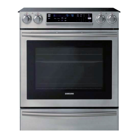
- Page 1 SLIDE IN RANGE BASIC: FER710DRS MODEL: NE58F9710WS MODEL CODE: NE58F9710WS/AC FREE STANDING RANGE 1. Precaution 3. Disassembly and Reassembly 4. Troubleshooting 5. PCB Diagrams 6. Wiring Diagram Refer to the service manual in the GSPN(see rear cover) for the more information.
-
Page 2: Table Of Contents
1. Precaution ................3 1-1 Forward . -
Page 3: Precaution
1-2 Safety Precautions dangerous situations. If you need repairs, contact a SAMSUNG Service Center or your dealer. WARNING to avoid electrical shock. SAMSUNG Electronics assumes no responsibility for any repairs made on our products by anyone other than Authorized Service Technicians. -
Page 4: Important Safety Instructions
1. Precaution 1-3 Important Safety Instructions For further assistance contact your service agent or manufacturer. WARNING This symbol will help alert you to hazards or unsafe practices which could cause serious bodily harm or death. s properly installed and CAUTION Do not store items of interest to children in cabinets above a range or on the back guard of a range –... - Page 5 1. Precaution SURFACE COOKING UNITS VENTILATING HOODS: Use Proper Pan Size Clean Ventilating Hoods Frequently – Grease with one or more surface units of different sizes. to cover the surface unit heating element. The use of undersized utensils will expose a portion of the OVEN heating element to direct contact and may result in ignition of clothing.
-
Page 6: Model & Serial Number Label And Tech Sheet Locations
1. Precaution 1-4 Model & Serial Number Label and Tech Sheet Locations Model & Serial Number Location Tech Sheet Location (On Low Rear Cover) -
Page 7: Features
Casual clean without any smell More frequently - Samsung : 5.8 cu.ft (Upper 2.7 / Lower 3.0 cu.ft) - Samsung : Pyrolitic + Steam Clean - Competitors - Competitors : Pyrolitic A : 5.4 cu.ft B : 5.3 cu.ft Features... - Page 8 Model Items BASIC MODEL NEW MODEL Model Name FER710DRS NE58F9710WS Category Convection Convection Width 30″ 30″ Overall Installation type Freestanding Slide in Color availability Oven Touch Touch Cooktop Knob Knob Display Control Electronic clock Control lock capability Audible preheat signal...
-
Page 9: Accessory
2-3 Accessory Item Description Code No. Q’ty RACK-FLAT DG75-01001C SENSOR-PROBE DG32-00013A ASSY-PARTITION FLEX DG94-00484A ASSY WIRE RACK DG94-00908A RACK WIRE-BOTTOM DG75-01056A... -
Page 10: Disassembly And Reassembly
3. Disassembly and Reassembly WARNING ELECTRICAL SHOCK HAZARD Disconnect power before servicing the range. Replace all panels before operating range. Failure to do so can result in death or electrical shock. 3-1 Removing the Assy-Frame Cooktop Item How to use Pictures Screw driver Use for assembly and disassembly of all screws... -
Page 11: Removing Pcb-Main
3. Disassembly and Reassembly 3-3 Removing PCB-Main WARNING ELECTRICAL SHOCK HAZARD Disconnect power before servicing the range. Replace all panels before operating range. Failure to do so can result in death or electrical shock. PRECAUTION When you work on the electric range, be careful when handling the sheet metal parts. Sharp edges may be present, and you can cut yourself if you are not careful. -
Page 12: Removing Touch Pcb
3. Disassembly and Reassembly 3-4 Removing Touch PCB WARNING Disconnect power before servicing the range Replace all panels before operating range. Failure to do so can result in death or electrical shock. PRECAUTION When you work on the electric range, be careful when handling the sheet metal parts. Sharp edges may be present, and you can cut yourself if you are not careful. -
Page 13: Removing Surface Elements And The Ceramic Glass Cooktop
3. Disassembly and Reassembly 3-5 Removing Surface elements and The Ceramic Glass Cooktop WARNING ELECTRICAL SHOCK HAZARD Disconnect power before servicing the range. Replace all panels before operating range. Failure to do so can result in death or electrical shock.. Parts Explanation Photo Explanation... -
Page 14: Removing The Latch-Door & Switch-Door Plunger
3. Disassembly and Reassembly 3-6 Removing The Latch-Door & Switch-Door Plunger WARNING ELECTRICAL SHOCK HAZARD Disconnect power before servicing the range. Replace all panels before operating range. Failure to do so can result in death or electrical shock. CAUTION When you work on the electric range, be careful when handling the sheet metal parts. Sharp edges may be present, and you can cut yourself if you are not careful. -
Page 15: Removing Heater-Broil
3. Disassembly and Reassembly 3-7 Removing Heater-Broil WARNING Disconnect power before servicing the range. Replace all panels before operating range. Failure to do so can result in death or electrical shock. CAUTION When you work on the electric range, be careful when handling the sheet metal parts. Sharp edges may be present, and you can cut yourself if you are not careful. -
Page 16: Removing Heater-Bake
3. Disassembly and Reassembly 3-8 Removing Heater-Bake Parts Explanation Photo Explanation Unplug range or disconnect power. Pull the range out of its mounting location so that you can access the rear of the unit. Remove Cover-Back Main Wire. (See step 3~4 on page 10 for procedure) Remove Terminal-Block and Bracket-Cover Access(with Adiabatic-Terminal) by unscrew 3 points. -
Page 17: Removing Convection Element, Fan-Convection And Motor-Convection
3. Disassembly and Reassembly Parts Explanation Photo Explanation Disconnect power and remove oven racks. Pull the range out of its mounting location so that you can access the rear of the unit. Remove Cover-Back Main Wire from the unit. (See step 3 on page 10 for procedure) Bracket convection Remove oven door. -
Page 18: Removing Lamp
3. Disassembly and Reassembly 3-10 Removing Lamp WARNING Disconnect power before servicing the range. Replace all panels before operating range. Failure to do so can result in death or electrical shock. CAUTION When you work on the electric range, be careful when handling the sheet metal parts. Sharp edges may be present, and you can cut yourself if you are not careful. -
Page 19: Removing Sensor-Thermistor
3. Disassembly and Reassembly 3-11 Removing Sensor-Thermistor WARNING ELECTRICAL SHOCK HAZARD Disconnect power before servicing the range. Replace all panels before operating range. Failure to do so can result in death or electrical shock. PRECAUTION When you work on the electric range, be careful when handling the sheet metal parts. Sharp edges may be present, and you can cut yourself if you are not careful. -
Page 20: Removing Assy-Partition Switch
3. Disassembly and Reassembly 3-12 Removing Assy-Partition Switch WARNING ELECTRICAL SHOCK HAZARD Disconnect power before servicing the range. Replace all panels before operating range. Failure to do so can result in death or electrical shock. PRECAUTION When you work on the electric range, be careful when handling the sheet metal parts. Sharp edges may be present, and you can cut yourself if you are not careful. -
Page 21: Removing Assy-Drawer & Heater-Warming Drawer
3. Disassembly and Reassembly 3-13 Removing Assy-Drawer & Heater-Warming Drawer (Continued) WARNING ELECTRICAL SHOCK HAZARD Disconnect power before servicing the range. Replace all panels before operating range. Failure to do so can result in death or electrical shock. PRECAUTION When you work on the electric range, be careful when handling the sheet metal parts. Sharp edges may be present, and you can cut yourself if you are not careful. - Page 22 3. Disassembly and Reassembly 3-13 Removing Assy-Drawer & Heater-Warming Drawer Parts Explanation Photo Explanation To remove Heater-Warming Drawer: Remove the screw from Bracket- Warming Heater. Assy-Drawer & Heater- Warming Drawer Remove Cover-Warming Heater and disconnect 2 wires. Pull out the Heater-Warming Drawer. * Reassembly of All part is the reverse order of disassembly.
-
Page 23: Removing And Replacing Oven Door
3. Disassembly and Reassembly 3-14 Removing and Replacing Oven Door WARNING The door is very heavy. Be careful when removing door Do not lift door up by the Handle-Door. Parts Explanation Photo Explanation To remove Oven Door: Fully open the door Pull the hinge locks downward. -
Page 24: Removing Handle-Door And Glass-Inner
3. Disassembly and Reassembly 3-15 Removing Handle-Door and Glass-Inner (Continued) WARNING ELECTRICAL SHOCK HAZARD Disconnect power before servicing the range. Replace all panels before operating range. Failure to do so can result in death or electrical shock. PRECAUTION When you work on the electric range, be careful when handling the sheet metal parts. Sharp edges may be present, and you can cut yourself if you are not careful. - Page 25 3. Disassembly and Reassembly 3-15 Removing Handle-Door and Glass-Inner (Continued) Parts Explanation Photo Explanation To remove Handle-Door Handle Remove 2 screws to remove Handle- Door Door To remove Glass-Inner Remove 6screws from rear side of door to remove 2 Hinge-Door. Glass-Inner Remove 4screws ro remove Glass- Inner Sub Assembly...
- Page 26 3. Disassembly and Reassembly 3-15 Removing Handle-Door and Glass-Inner Parts Explanation Photo Explanation Handle Door Explanation Photo Explanation * Reassembly of All part is the reverse order of disassembly.
-
Page 27: Removing Gasket-Door
3. Disassembly and Reassembly 3-16 Removing Gasket-Door WARNING ELECTRICAL SHOCK HAZARD Disconnect power before servicing the range. Replace all panels before operating range. Failure to do so can result in death or electrical shock. PRECAUTION When you work on the electric range, be careful when handling the sheet metal parts. Sharp edges may be present, and you can cut yourself if you are not careful. -
Page 28: Removing The Panel-Side
3. Disassembly and Reassembly 3-17 Removing The Panel-Side WARNING ELECTRICAL SHOCK HAZARD Disconnect power before servicing the range. Replace all panels before operating range. Failure to do so can result in death or electrical shock. PRECAUTION When you work on the electric range, be careful when handling the sheet metal parts. Sharp edges may be present, and you can cut yourself if you are not careful. -
Page 29: Troubleshooting
4. Troubleshooting 4. Troubleshooting 4-1 Failure Display Codes There is a error code and two kinds of error codes. Possible error codes during use can be checked before service. 1. Touch ‘Clock 2. Touch a number ‘ 3. Touch ‘Oven Start / Set 4. - Page 30 4. Troubleshooting 4-1 Failure Display Codes Failure code CAUSE SOLUTION 1. Disconnect power. Open the back cover. Disconnect sensor Oven sensor opened E-21 sensor. 2. If there is not any problem with oven sensor, Please check whether there is a damaged therminal or wire on harness. Oven sensor shorted E-22 3.
- Page 31 4. Troubleshooting 4-1 Failure Display Codes "E-21" "E-22" oven sensor oven sensor Disconnect power Measure sensor resistance. *reconnect...
- Page 32 4. Troubleshooting 4-1 Failure Display Codes Safety error “E-24” Convection Relay “E-0E” DLB Relay Broil Relay Disconnect power and sub PCB Bake Relay Main PCB Main PCB * DLB, Bake, Broil,convection relay * Replace main PCB check.(Nomal: * Solder again if pattern is damaged * Check whether there is any damaged or parts is wrong contacted.
- Page 33 4. Troubleshooting 4-1 Failure Display Codes E-0E *Disconnect power. *Get rid of harness connected with Lock motor Door lock motor Door lock motor * Micom switch check (com-NC,com-NO) * Measure resistance of Lock motor * Replace micro switch or Lock motor. * Check oven sensor (See page 31) *Check whether...
- Page 34 4. Troubleshooting 4-1 Failure Display Codes CN201 E-83 * Disconnect power. TE400 * Get rid of connector (TE400,CN201) on Sub PCB, Main PCB. Sub PCB Main PCB * Check whether harness connected * Repair damaged harness or replace. normally into TE400,CN201 on Sub PCB, Main PCB.
- Page 35 4. Troubleshooting 4-1 Failure Display Codes -tE- TE201 * Disconnect power. Sub PCB * Get rid of connector(TE201) on Sub PCB. * Check connected normally into Touch glass, TE201 on Sub PCB * Repair damaged wire or replace.
- Page 36 4. Troubleshooting 4-1 Failure Display Codes - SE - Connector (TE201) *Disconnect power. *Take out keypad cable from the Sub PCB. * Repair the area of circuit having short between connector(TE201) pins on * Check whether between connector(TE201) Sub PCB. pin and pin on sub PCB have a short * Repair after confirming circuit.
- Page 37 4. Troubleshooting 4-1 Failure Display Codes -dE- * Disconnect power. * Get rid of harness connected with partition Partition Switch switch. * Measure resistance of partition switch. * Replace partition switch. * Check whether harness connected * Repair damaged harness or replace. normally into CN401 of main PCB.
- Page 38 4. Troubleshooting 4-1 Failure Display Codes E-2E * Disconnect power. * Get rid of harness connected with Meat probe. < Meat Probe > * Replace Meat probe. * Check whether harness connected normally * Replace Meat probe. into CN401 of main PCB. * Measure resistance CN401 of main PCB.
- Page 39 4. Troubleshooting Control PCB Operation Sort of Control PCB Main PCB ( Front ) ( Back ) Sub PCB ( Front ) ( Front ) ( Back )
- Page 40 4. Troubleshooting Explain of primary parts of Main PCB (Main PCB) CN202 CN201 CN301 CN401 IC102 CN101 RY502 RY503 RY504 CN501 CN502 Explatin of the function of primary parts. CN101 This is to supply power with SMPS. CN201 This is connector which is connected with Sub PCB to communicate. When do micom revision, connect to micom writer.
- Page 41 4. Troubleshooting Explain primary parts of Sub PCB TE400 CN400 CN200 CN502 Explatin of the function of primary parts. TE400 This is connector which is connected with Main PCB to communicate. When do micom revision, connect to micom writer. CN400 (No connection at normal times) When do micom revision, connect to micom writer.
- Page 42 4. Troubleshooting SYMPTOM DIAGNOSIS REMEDY Check circuit breaker. Make sure that the state of wire is Measure an input voltage of terminal connected with Terminal block. block. Measure voltage of connector(CN08,CN09) on main Replace of repair if harness has been PCB L1~N : 120V loosen or disconnected.
- Page 43 4. Troubleshooting SYMPTOM DIAGNOSIS REMEDY Check whether temperature is risen Replace or repair it if relay on sub PCB or main have a short circuit. in a state of room temperature. Oven temperature is risen fast. Check whether harness has been Replace or repair harness.
- Page 44 4. Troubleshooting SYMPTOM DIAGNOSIS REMEDY Check whether Convection fan Replace or repair Relay. relay (Ry08) on sub PCB and Replace or repair connector. connector(CN01) is in normal. Convection fan is Make sure whether harness between Replace or repair harness. not rotated. connector(CN04, CN05) on sub PCB Replace or repair connector.
-
Page 45: Electrical Malfunction
4. Troubleshooting 4-2 Electrical Malfunction Troubleshooting (Power) No Power Check the circuit breaker. Check terminal block voltage. Check the terminal block connections (240V,60Hz) Replace or Repair the wiring Check the wiring. Check the votage of PCB, SMPS -input : 120V -output : 12V,5V Replace the defected PCB. - Page 46 4. Troubleshooting 4-2 Electrical Malfunction Troubleshooting (PCB failure) PCB Failure - Check the input voltage of Repair Faulty wiring - Check Terminal block PCB SMPS (input check- or PCB check voltage(240V). point : 120V ) Reset the circuit braker or check main power.
- Page 47 4. Troubleshooting 4-2 Electrical Malfunction Component testing procedures WARNING ELECTRICAL SHOCK HAZARD Disconnect power before servicing the range. Replace all panels before operating range. Failure to do so can result in death or electrical shock. FIGURE TESTS MEASURE RESULTS Measure resistance values of (at the room temperature) harness from heater.
- Page 48 4. Troubleshooting 4-2 Electrical Malfunction FIGURE TESTS MEASURE RESULTS Lock motor Measure the state of micro switch and motor after taking off harness (at the room temperature) from the heater. voltage : 120V Check whether the lock works Micro switch normally by pressing cooking time COM-NO button and delay start keypad at the...
- Page 49 4. Troubleshooting 4-2 Electrical Malfunction FIGURE TESTS MEASURE RESULTS Check the state of working of switch. Nomal close : Make sure whether wire, housing Replace or repair if wire or and terminal is connected with switch terminal has been damaged. has been damaged or not.
- Page 50 4. Troubleshooting 4-2 Electrical Malfunction Oven sensor resistance (Temperature vs. Sensor resistance) degree F degree C ohms degree F degree C ohms -17.8 932.12 1170.17 961.86 1188.93 980.95 1374.93 1000.00 1558.01 1019.02 1738.06 1038.02 1915.39 1056.99 2089.69 1075.92 2261.07 1094.83 2429.52 1113.71 2595.05...
-
Page 51: Pcb Diagrams
5. PCB Diagrams 5-1 PCB Diagrams (Main) (This Document can not be used without Samsung’s authorization) Parts Number Part Name Function and Rule RY501 RY-Source Relay Circuit is designed to have broil relay or convection relay worked after DLB relay is being worked by Double line break. -
Page 52: Pcb Diagrams (Sub)
5. PCB Diagrams 5-2 PCB Diagrams (Sub) (This Document can not be used without Samsung’s authorization) Parts Number Part Name Function and Rule TE400 Main Communication Connector This is connector which is connected with Main PCB to communicate. CN200 On Board Writing Connector... -
Page 53: Wiring Diagram
6. Wiring diagram 6-1 Wiring diagram (This Document can not be used without Samsung’s authorization) - Page 54 GSPN (GLOBAL SERVICE PARTNER NETWORK) Area Web Site Europe, CIS, Mideast & Africa gspn1.samsungcsportal.com Asia gspn2.samsungcsportal.com North & Latin America gspn3.samsungcsportal.com China china.samsungportal.com © Samsung Electronics Co., Ltd. June. 2013 Printed in Korea...