Advantage Controls MegaTronXS Installation Maintenance Repair Manual
Hide thumbs
Also See for MegaTronXS:
- Quick steps (2 pages) ,
- Upgrade instructions (2 pages) ,
- Installation, maintenance and repair manual (32 pages)
Table of Contents

Related Manuals for Advantage Controls MegaTronXS


Summary of Contents for Advantage Controls MegaTronXS
- Page 1 Manual Controller Installation Maintenance Repair Manual Advantage Controls 4700 Harold Abitz Dr. Muskogee, OK 74403 Phone: (800) 743-7431 Fax: (888) 686-6212 www.advantagecontrols.com 08/2023 email: support@advantagecontrols.com...
-
Page 2: Table Of Contents
MegaTronXS Controller Instruction & Maintenance Manual Table of Contents Contents Page Introduction ................. 3 Model Numbering ............... 3 Description of Unit ..............3 Installation .................. 4 Electrical Wiring ................4 Wiring Diagrams ................. 5 Mounting Instructions ..............8 Electrode Installation ..............8 A. -
Page 3: Introduction
Model Numbering table listed below. Model Numbering MegaTronXS units have several base system control functions and unit optional features. Your unit may be supplied with one or more of the features described in this manual. To determine what features apply to your unit check the model number label located on the controller enclosure. -
Page 4: Installation
Chemical Feed Timers Chemical feed timers are designed to automate the addition of various chemicals by activating a relay output. Multiple timers can be supplied depending upon the model number and each timer will include a relay output. All timers can be programmed to be one of the following types. Pulse Time - Accepts pulses from a make-up water meter (supplied separately). -
Page 5: Wiring Diagrams
NOTES: 1. Liquid tight fittings and some labeled signal leads are provided for all signal (low voltage) connections for both pre-wired and conduit units. 2. Units should be ordered with the appropriate option to provide powered relays designed for the incoming/outgoing power. - Page 6 Motherboard Connections Aux Flow Inputs System 4-20mA Comm Card Open Input 1 Slot Slot Slot Input 2 Input 3 Input 4 VDC Output Connections Cable System Card Connections Standard System Card Misc. Conductivity Black Temperature Green Note: Conductivity probe’s wire colors White White White...
- Page 7 4-20mA Output Card Wiring Isolated Configuration For isolated 4-20mA outputs an external power source for the loop must be supplied. JP4 and JP5 on the board must be jumpered for isolated with an external power source supplied to the external VDC input. The external power source must not exceed 24 volts DC.
-
Page 8: Mounting Instructions
Electrode Installation MegaTronXS controllers may come configured for various circulating water systems. Listed below are instructions for typical cooling tower and boiler installations. Your specific installation requirements may differ but should conform to these instructions as much as possible for proper operation. - Page 9 Typical Cooling Tower Installation Diagram COOLING TOWER SET UP ENTER HOME BLOWDOWN CANCEL HELP BACK BLEED VALVE MAKE-UP WATERMETER TO DRAIN PUMP CIRCULATION CHILLER Cooling Tower Probe Assembly FS-FC TFS-C FS-0C TFS-OC 1A9A000262 E-30-PH pH Probe PE-21 FS-T -or- OE-21 ORP Probe PE-NUT FS-B1-SP...
-
Page 10: Boiler
Boiler Standard boiler electrodes have a MNPT stainless steel bushing and are supplied with a FNPT cross designed for mounting in the skimmer (surface) blowdown line. Sampling of the boiler’s water can be achieved using one of two typical plumbing configurations (continuous sampling or timed and/or sample &... - Page 11 Typical Continuous Sampling Installation Fully ported gate or ball valve Throttling device SET UP ENTER HOME 1" Continuous CANCEL HELP BACK blow down line Electrode within a 1" cross with electrical 1/2" pipe connection vented Electrically between probe actuated and throttle blow down device and valve...
-
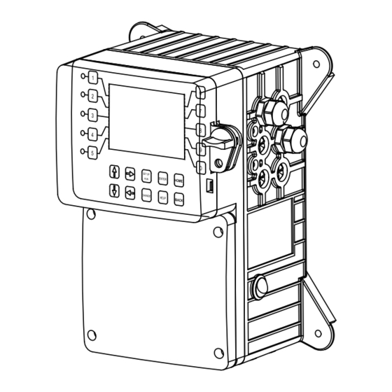
Page 12: Front Panel Drawing
III. Front Panel Description ACI MEGATRON SYS1: TOWER CARD 1 COND 1,400 uS/cm STATUS SYS OK 375 mV TEMP: 72.1F FLOW: ON SYSTEM OK <HOT KEY> Thursday, August 29, 2013 02:24:10 PM (Wk1) SET UP ENTER HOME CANCEL HELP BACK NUMBER Keys- Used to enter new values in the SET UP mode and to access desired sub menus. -
Page 13: System Operation Overview
Calibration All MegaTronXS controllers are factory calibrated for temperature, conductivity, pH and ORP. All units are shipped with the date preset, and the clock set to your current time. These readings and settings should be verified for accuracy and adjusted as per the instructions listed below. -
Page 14: Menu Navigation
To access the menus press the Set Up / Run key on the front panel. This takes you to the Home menu. MegaTronXS controller’s menus are easily navigated by pressing the associated number key next to a menu box on the screen. Once you have stepped through the sub menus to reach a point at which a value or selection is made a Pop-up window will appear prompting you to enter a desired value or selection. - Page 15 Set Point Options SET POINT - What reading turns the relay on >SYSTEM 1 COND SETPOINT< DIFFERENTIAL - Amount reading changes by before SET POINT SET POINT the relay is turned off DIFFERENTIAL HIGH ALARM - What reading generates a High alarm. LOW ALARM - What reading generates a Low alarm.
- Page 16 The ORP set point settings follow the same format as shown above in section 2.1 and 2.3. ORP SET POINT 2 - If a 28-day timer is interlocked >SYSTEM 1 ORP SETPOINT< to ORP, the ORP control will go off of SET POINT 2 SET POINT SET POINT 2 during the 28-day timer’s run time.
- Page 17 Auxiliary inputs are the digital inputs for optional Flow Switch and other digital inputs such as low drum level alarms. From these menus the user can set if they want each of the alarms Displayed, Remote Notification, both or none. Note: Digital inputs can have the direction selected >SYSTEM 1 DIGITAL INPUTS ALARM<...
- Page 18 CALIBRATE - With a clean probe inline with the >SYSTEM 1 COND CALIBRATION< system’s water, enter the known (from a calibrated CALIBRATE Cal Factor 1.10 hand-held tester) value. Note: Never enter 0. RESET ZERO - With the probe out of solution and dry RESET ZERO enter a new zero point.
- Page 19 4-20mA inputs can be calibrated to ensure that the input seen by the controller from the external device match. It also allows for setting the 4-20mA input into a number range that relates to the value being read. >CURRENT LOOP CALIBRATION< INPUT 1 Select the Input to be calibrated INPUT 2...
- Page 20 A pop-up screen lets you scroll through the various timer types available. Pulse - A water meter activated timer >SYSTEM 1 TIMER 1 SET UP< Limit - Feed with bleed with a maximum run time or limit >SET TIMER TYPE (PULSE)< for one bleed cycle.
- Page 21 % of BLEED - The % of the post bleed time or other source time that you want the timer to run. LIMIT TIMER - The limit timer is a safety feature that limits a single feed cycle to the amount of time set regardless of the calculated post feed %.
- Page 22 RUN SCREEN - Allows the user to select what will be shown on the screen while the controller is in the RUN mode. Like displaying temperature readings, water meter totals for a particular system or the conductivity units of measure. NOTE: When entering values for custom names use the numerical keys for numbers and the up / down arrows to scroll through all the characters of a key board.
- Page 23 screens are scrolled. CYCLE TIME - The amount of time between screen scrolls. COND UNITS - Select the units of measure to be displayed with the conductivity reading. Alarms ALARMS - Shows any current alarms. >ALARMS< SYS 1 ALARMS Date and Time Set Up DATE AND TIME - For setting the date, time, day and >SET DATE AND TIMES<...
- Page 24 Additional relay logic is available with up to 3 additional Activators and up to 4 Disablers allowing multiple functions to activate the same relay and multiple functions to prevent the relay from coming on. There is also a Daily Max amount of time that a relay can be on. If a relay is on for the max amount, it does not let the relay come on anymore that day.
- Page 25 Note: The Network card must be RESET after making any changes to Network setting in order to save changes and reset communications. System Information System information will identify the version of firmware installed in the controller along with the controller’s serial number.
- Page 26 A unit may have 1 to 4 Aux Meters. These additional inputs are for tracking various flow meter devices like Advantage Controls’ FloTracker in a metering pump’s discharge tubing. They can also be linked to a system’s water meter input for additional tracking and alarm capabilities.
- Page 27 10.2a Aux Meter Review A review screen of the current settings is provided with a selection for the Tracking method and the Settings. SETTINGS - Access the various settings for the flow >FLOW METER 1< meter. TOTAL VALUE: 9966.0 ML FLOW RATE: 0.0 ML/MIN TRACKING - Provides a pop-up screen to select...
- Page 28 meter inputs. If this is selected no wiring to the auxiliary input is required and the PULSE VALUE and UNITS settings are auto populated from the particular water meter’s settings. Relays >RELAYS< STATUS - Allows for viewing accumulated relay ON times, temporary forcing relays ON or OFF or seeing STATUS which relay is on.
-
Page 29: Usb Functions
MegaTron Quick Steps XS Controller - USB Functions Step 1: The XS is capable of transferring information using a FAT formatted USB drive. The XS has To transfer the contents of the XS history logs to the three main USB functions as detailed in the USB drive, select →... - Page 30 >CONFIGURE< history to be stored on WebAdvantage for using custom PASSWORD CONTRAST graphing and multiple user internet access. Contact RELAYS TEMP SCALE Advantage Controls or support@advantagecontrols.com NETWORK with your unit’s serial number to learn more. HISTORY SYS INFO FLOW SW...
-
Page 31: Maintenance
The MegaTronXS controller is designed for many years of trouble-free operation. Should a problem occur, refer to the following chart to help identify the problem. If replacement is required, follow the procedures listed in the Warranty and Factory Service portion of this manual. -
Page 32: Electrode Cleaning Procedures
IX. Advantage Controls’ Product Warranty Advantage Controls warrants control systems of its manufacture to be free of defects in material or workmanship. Liability under this policy extends for 24 months from date of installation. Liability is limited... - Page 33 30 Day Billing Memo Policy Advantage Controls maintains a unique factory exchange program to ensure uninterrupted service with minimum downtime. If your controller malfunctions, call 1(918)-686-6211, provide our technician with Model and Serial Number information. If they are unable to diagnose and solve your problem over the phone, a fully warranted replacement will be shipped, usually within 48 hours, on a 30-Day Billing Memo.
-
Page 34: Warranty & 30 Day Billing Memo Policy
N.O. SOLENOID MOTORIZED BALL VALVE MBWA 1075 LIMIT SWITCH MBWB 1036 Aux Flow Inputs System 4-20mA Comm Card Open Input 1 Wiring for Slot Slot Slot Input 2 Input 3 MegaTron XS Input 4 VDC Output Connections Refer to manual for additional information Cable... - Page 35 N.C. N.O. COM (1 - WHITE) N.O. (2 - BLACK) GND ( - GREEN) SOLENOID VALVE (TOP VIEW) MBWB 1036 MOTORIZED BALL VALVE (SIDE VIEW) MBWA 1075 BLOWDOWN VALVE (TOP VIEW)
- Page 36 Pyxis STA-500 Sensors Aux Flow Inputs System 4-20mA Comm Card Open Input 1 Wiring for Slot Slot Slot Input 2 Input 3 MegaTron XS Input 4 VDC Output Connections Note: Refer to full manual for additional information Cable Input 1 - Input 1 + GREEN (-4-20) WHITE (+4-20)
- Page 37 Pyxis STA Dual Output Aux Flow Inputs Sensors: System 4-20mA Comm Card Open Input 1 Slot Slot Slot Input 2 Input 3 Input 4 VDC Output - 588 Tagged Polymer & PTSA Connections - FCLSS Free Chlorine & pH (765) - CLOSS Chlorine Dioxide &...
- Page 38 Pyxis STA-525 series sensors Wiring for MegaTrons Jumper Block Note: Refer to full manual for Spare Power additional information Pyxis changed the wiring on the 525 Cable series of sensors in late 2022 so that there is not a -4-20 Input 1 - WHITE (+4-20) wire.
- Page 39 CABLE-7P-2A Wiring a Nano-M to a MegaTronXS, or *Other Building Management System Note: Refer to full manual for Aux Flow Inputs additional information System 4-20mA Comm Card Open Input 1 Slot Slot Slot Input 2 Input 3 Input 4 VDC Output...
- Page 40 Get the Advantage in Water Treatment Equipment Advantage Controls can give you the Advantage in products, knowledge and support on all of your water treatment equipment needs. Cooling Tower Controllers Boiler Blow Down Controllers Blow Down Valve Packages Solenoid Valves...
Need help?
Do you have a question about the MegaTronXS and is the answer not in the manual?
Questions and answers