Table of Contents
Advertisement
Quick Links
Advertisement
Table of Contents

Related Manuals for Advantage Controls MegaTrom XSi


Summary of Contents for Advantage Controls MegaTrom XSi
- Page 1 Web Monitor Product Manual Important Safety Instructions Read all warnings and instructions in this manual. Save all instructions. Advantage Controls 4700 Harold-Abitz Dr. Muskogee, OK 74403 Phone: 800-743-7431 Fax: 888-686-6212 www.advantagecontrols.com support@advantagecontrols.com 09/2021...
-
Page 2: Table Of Contents
MegaTronXSi Web Monitor Instruction & Maintenance Manual Table of Contents Contents Page Introduction ................. 3 Model Numbering ............... 3 Description of Unit / Control Functions ........3 Installation .................. 4 Mounting Instructions ..............4 Electrical Wiring ................4 Wiring Diagrams ................. 4 III. -
Page 3: Introduction
Introduction The MegaTronXSi microprocessor based controllers are designed to provide a wide range of web monitoring functions. The controller is programmed through a front panel keypad or via the internet through WebAdvantage and can be configured to provide a customized web monitoring for your application. Your particular unit’s functions can be determined by comparing the units model number to the Model Numbering table listed below. -
Page 4: Installation
Installation Mounting Instructions Select a mounting location that provides the operator easy access to the unit and a clear view of the controls through the cover of the controller. The location should be convenient to grounded electrical connections, the needed sample line plumbing, and should be on a stable vertical surface. Electrical Wiring The MegaTron XSi monitor has an internal regulated fused power supply that will operate off of 90 to 250 VAC at 47 to 63 Hz on the incoming wiring. - Page 5 The control function that activates each relay output is pre-configured at the factory based on the options selected. To change relay activation, see on page 13. Refer to label inside lower panel cover for specific relay board configuration supplied. Relays configured as “dry contact” should only have D.C. voltage ran through them. The GND connection point replaces the NEU when configured for dry contact.
- Page 6 4-20mA Output Card Wiring Isolated Configuration For isolated 4-20mA outputs an external power source for the loop must be supplied. JP4 and JP5 on the board must be jumpered for isolated with an external power source supplied to the external VDC input. The external power source must not exceed 24 volts DC.
-
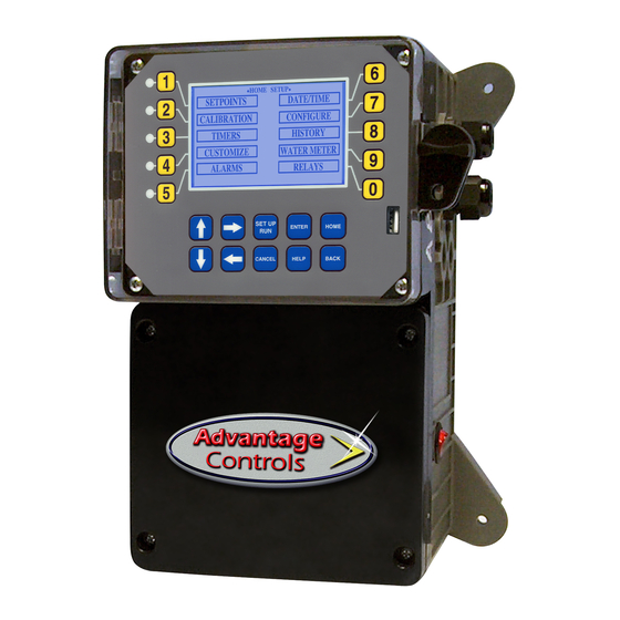
Page 7: Front Panel Description
III. Front Panel Description ACI MEGATRON SYS1: PROCESS 1 COND 1,400 uS/cm STATUS SYS OK TEMP: 72.1F SYSTEM OK <HOT KEY> Thursday, August 29, 2013 02:24:10 PM (Wk1) SET UP ENTER HOME CANCEL HELP BACK NUMBER Keys- Used to enter new values in the SET UP mode and to access desired sub menus. UP/DOWN - Used to cycle through text options to find desired setting. -
Page 8: System Operation Overview
IV. System Operation Overview Operation MegaTron XSi controllers have two modes of operation, RUN and SET-UP. - This mode is for normal operation. In the RUN mode the display will show each system’s parameters. If an alarm is present, the ALARM box will flash how many alarms are activated. No settings may be entered or changed in the RUN mode. - Page 9 Set Points The same basic format is used for defining each available analog mA control parameters. >SYSTEM 1 SET POINTS< SET POINTS - For setting the relay set points for the available analog readings. mA OUT mA IN AUX INPUTS NOTE: In the Setpoint pop-up screen the direction (Rising or Falling) of the setpoint can also be set.
- Page 10 4-20mA Out Units with a 4-20mA output option will have a menu for setting up the 4-20mA output. The 4mA and 20mA values can be defined by giving the output proportioning capability. i.e. 4mA = a pH of 6.0 and 20mA = a pH of 8.0.
- Page 11 >mA INPUT 1 CALIBRATION< 20mA 5500 1100 OFFSET FACTORY DEF. The 20mA and 4mA values are where the controller’s raw analog to digital value is adjusted to match a 20mA (full scale) and 4mA (bottom of scale) signal from the external device inputting the 4-20mA input. The external device must be connected to the controller and showing either full scale or bottom of scale when calibrating each.
- Page 12 NAME - Pick from a list of defined names or customize >NOTEPAD SYS 1 NOTE 1< your own. NAME NUMBER - Set the number range. NUMBER UNITS - Set the units of measurement. UNITS ALARMS - Set Hi/Low alarm points and how frequently a new value is expected to be manually enter via the ALARMS History menu.
- Page 13 CONTRAST - This screen allows for adjusting the >CONFIGURE< display contrast. PASSWORD CONTRAST FACTORY - A factory only menu RELAYS TEMP SCALE - Set Celsius or Fahrenheit NETWORK HISTORY - Sets the history time stamp interval. SYS INFO - Tells unit software specifics. HISTORY SYS INFO FACTORY...
- Page 14 Contrast This menu is used to adjust the contrast of the display. Network The Network menu is used when a controller is being remotely communicated with either a local network connection or over the internet on the Web Advantage server. NETWORK - This menu is used for setting up the >NETWORK<...
- Page 15 NOTE: The history can be reset by going to the >HOME REVIEW< configure menu and entering a different sample SYSTEM 1 interval. After the new sample interval has been set Sample Time: 5 MIN (Length 164.62 days) the onboard history is reset. Sensor Samples Relay/Alarm Events Notepad Entries...
- Page 16 A unit may have 1 to 4 Aux Meters. These additional inputs are for tracking various flow meter devices like Advantage Controls’ FloTracker in a metering pump’s discharge tubing. They can also be linked to a system’s water meter input for additional tracking and alarm capabilities.
-
Page 17: Webadvantage Setup
Note: If Rate and Volume tracking has been selected an alarm will occur if the defined MAX VOLUME amount is measured within the defined TIME CYCLE which can be a 12-or-24 hour period. RESET VOLUME - Resets the Volume Alarm totalizer. METER LINK –... - Page 18 USER ID Setup Setting Up a USER ID Before you can view a device, a USER ID must be setup. Note: If you already have a USER ID and are just adding a new device, skip to step 4. Step 1: Visit https://webadvantage.online or access the registration form with the QR...
- Page 19 Admins Only: Add Device and Assign USER ID Setting Up / Accessing a Device Note: USER ID and Company Access Permissions Note: Please allow up to 24 hrs for processing before are required before you can access a device. For controller shows in device list.
-
Page 20: Usb Functions
MegaTron Quick Steps XS Controller - USB Functions Step 1: The XS is capable of transferring information using a FAT formatted USB drive. The XS has To transfer the contents of the XS history logs to the three main USB functions as detailed in the USB drive, select →... - Page 21 >CONFIGURE< history to be stored on WebAdvantage for using custom PASSWORD CONTRAST graphing and multiple user internet access. Contact RELAYS TEMP SCALE Advantage Controls or support@advantagecontrols.com NETWORK with your unit’s serial number to learn more. HISTORY SYS INFO FLOW SW...
- Page 22 SYSTEM INFORMATION: >CONFIGURE< Step 2: XS MEGATRON CONTROLLER ADVANTAGE CONTROLS INC. PASSWORD CONTRAST Plug the USB drive into the XS that you would like FRMWARE REV: KA.10.03A Jan 29 2018 RELAYS S/N:...
-
Page 23: Troubleshooting
IX. Advantage Controls’ Product Warranty Advantage Controls warrants control systems of its manufacture to be free of defects in material or workmanship. Liability under this policy extends for 24 months from date of installation. Liability is limited to repair or replacement of any failed equipment or part proven defective in material or workmanship upon manufacturer’s examination. - Page 24 Get the Advantage in Water Treatment Equipment Advantage Controls can give you the Advantage in products, knowledge and support on all of your water treatment equipment needs. Cooling Tower Controllers Boiler Blow Down Controllers Blow Down Valve Packages Solenoid Valves...
Need help?
Do you have a question about the MegaTrom XSi and is the answer not in the manual?
Questions and answers