
Related Manuals for Rohde & Schwarz CMW 500


Summary of Contents for Rohde & Schwarz CMW 500
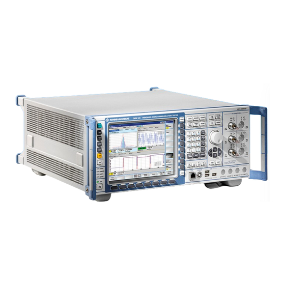
- Page 1 1202.3986.32 – 03 Test and Measurement Division Operating Manual ® R&S CMW 500 Wideband Radio Communication Tester...
- Page 2 Printed in Germany - Subject to change - Data without tolerance limits is not binding. ® R&S is a registered trademark of Rohde & Schwarz GmbH & Co. KG. Trade names are trademarks of the owners. The following abbreviations are used throughout this manual: ® R&S CMW 500 is abbreviated as R&S CMW 500.
- Page 3 Chapter 1 of this manual gives an overview of the front panel controls and connectors of the R&S CMW 500 Wideband Radio Communication Testers with display and gives all information that is necessary to put the instrument into operation and connect external devices.
-
Page 5: Table Of Contents
® R&S CMW 500 Contents Contents 1 Preparing for Use.................. 1 Front Panel Tour ......................1 1.1.1 Utility Keys ........................2 1.1.2 Status LEDs and Standby Key ..................2 1.1.3 Display ..........................3 1.1.4 Softkeys and Hotkeys ......................3 1.1.5 Setup Keys........................3 1.1.6 Data Entry Keys .......................4 1.1.7... - Page 6 1.5.3 Connecting a Printer ......................17 1.5.4 Connecting a Monitor.....................18 1.5.5 Connecting a LAN Cable ....................18 Starting the R&S CMW 500 and Shutting Down ............19 Remote Operation in a LAN ..................20 1.7.1 Assigning an IP Address....................20 1.7.2 Remote Desktop Connection..................22 Windows XP .........................22 Firmware Update......................22...
- Page 7 ® R&S CMW 500 Contents Measurements......................38 3.2.1 Measurement Control ....................38 3.2.2 Connection Control (Measurements)................39 3.2.3 Statistical Settings......................40 3.2.4 Statistical Results......................41 3.2.4.1 Statistics Type........................42 3.2.4.2 Detectors........................43 3.2.4.3 Peak Values........................43 3.2.4.4 Averaging........................44 3.2.4.5 Standard Deviation ......................44 3.2.5 Trigger Settings......................45 3.2.6 TX Measurements......................45 3.2.6.1...
- Page 8 ® R&S CMW 500 Contents 4.3.2.4 Performing Selftests.......................62 4.3.2.5 Selftest Parameters .......................63 4.3.3 Reference Frequency ....................65 4.3.3.1 Reference Frequency Settings ..................65 4.3.4 Measurement Controller Dialog ..................66 4.3.5 Generator Controller Dialog...................66 5 Remote Control ................... 68 Remote Control Operation..................68 5.1.1 Establishing and Testing a LAN Connection ..............70 5.1.2...
- Page 9 ® R&S CMW 500 Contents 5.4.1.3 ABORt:<Application>:MEASurement<i> ...............85 5.4.1.4 STOP:<Application>:MEASurement<i>.................85 5.4.1.5 Measurement Substates ....................85 5.4.2 Statistical Settings......................86 5.4.3 Retrieving Measurement Results...................88 5.4.3.1 FETCh...? Command .....................88 5.4.3.2 READ...? Command ......................89 5.4.3.3 Retrieving Single Values and Traces................90 5.4.4 Reliability Indicator......................90 5.4.4.1 Common Reliability Indicator ..................90 5.4.5...
- Page 10 ® R&S CMW 500 Contents 5.6.3.2 IST Flag and PPE ......................106 5.6.3.3 ESR and ESE ......................107 5.6.3.4 STATus:OPERation .....................108 5.6.3.5 STATus:QUEStionable ....................108 5.6.4 Application of the Status Reporting System ..............108 5.6.4.1 Service Request......................108 5.6.4.2 Serial Poll........................109 5.6.4.3 Parallel Poll ........................109 5.6.4.4...
- Page 11 ® R&S CMW 500 Contents 7.1.2.2 Single Power Steps and List Mode................136 7.1.2.3 Trigger Modes......................137 7.1.2.4 Measurement Settings ....................138 7.1.2.5 Power: Results......................138 7.1.3 External Power Sensor Measurement .................140 7.1.3.1 Sensor Connection and Test Setup................140 7.1.3.2 Measurement Settings ....................141 7.1.3.3 Zeroing.........................142 7.1.3.4...
- Page 12 ® R&S CMW 500 Contents 7.3.1.1 Key Features........................164 7.3.1.2 Generating a CW Signal ....................165 7.3.1.3 Generating a Dual-Tone Signal ...................165 7.3.1.4 Using the Generator List Mode..................166 7.3.2 Programming the Power Measurement ...............167 7.3.2.1 Key Features........................167 7.3.2.2 Specifying General Measurement Settings ..............168 7.3.2.3...
- Page 13 ® R&S CMW 500 Contents 7.4.3.2 Measurement Control and States ................184 7.4.3.3 Measurement Control Parameters................186 7.4.3.4 Statistical Settings......................187 7.4.3.5 Filter Settings .......................187 7.4.3.6 Trigger Settings......................188 7.4.3.7 List Configuration ......................190 7.4.3.8 Measurement Results ....................192 7.4.4 External Power Sensor Measurement Commands .............193 7.4.4.1...
- Page 14 ® R&S CMW 500 Contents 8.2.1.1 Measurement Control ....................224 8.2.1.2 Signal Routing and Analyzer Settings .................224 8.2.1.3 GSM Multi Evaluation Configuration: Measurement Control ........226 8.2.1.4 GSM Multi Evaluation Configuration: Trigger ..............233 8.2.1.5 GSM Multi Evaluation Configuration: Limits ..............235 8.2.1.6 GSM Multi Evaluation Configuration: Display..............238 8.2.1.7...
- Page 15 ® R&S CMW 500 Contents 8.4.2.8 Spectrum Modulation Settings..................264 8.4.2.9 Spectrum Switching Settings ..................266 8.4.2.10 Limits (GMSK Modulation) ...................267 8.4.2.11 Limits (8PSK Modulation) ....................271 8.4.2.12 Limits (Power vs. Time) ....................274 8.4.2.13 Limits (Spectrum Modulation) ..................278 8.4.2.14 Limits (Spectrum Switching) ..................281 8.4.2.15...
- Page 16 ® R&S CMW 500 Contents WCDMA GUI Reference .....................314 9.2.1 WCDMA Multi Evaluation: Parameters and Settings...........314 9.2.1.1 Measurement Control ....................315 9.2.1.2 Signal Routing and Analyzer Settings .................315 9.2.1.3 UE Signal Info ......................317 9.2.1.4 Multi Evaluation Settings .....................318 9.2.1.5 WCDMA Multi Evaluation Configuration: Trigger ............321 9.2.1.6...
- Page 17 ® R&S CMW 500 Contents 9.4.2.5 Statistical Settings (Spectrum)..................344 9.4.2.6 Trigger Settings......................345 9.4.2.7 Limits (Modulation).......................345 9.4.2.8 Limits (Spectrum)......................348 9.4.2.9 EVM Measurement Results (Traces)................349 9.4.2.10 Magnitude Error Measurement Results (Traces) ............352 9.4.2.11 Phase Error Measurement Results (Traces) ...............354 9.4.2.12 Spectrum Emission Measurement Results (Traces) ...........356 9.4.2.13...
- Page 18 ® R&S CMW 500 Contents 10.2.1.8 WiMAX Multi Evaluation: Results ................383 10.3 WiMAX Command Reference ...................388 10.3.1 General Measurement Settings ...................388 10.3.1.1 Command Groups (General Measurement Settings) ..........388 10.3.1.2 Analyzer Settings ......................388 10.3.1.3 Signal Routing......................389 10.3.2 WiMAX Multi Evaluation Measurement Commands............390 10.3.2.1...
- Page 19 ® R&S CMW 500 Contents 11.1.3.1 Interface Functions ......................418 11.1.3.2 Interface Messages......................419 11.1.3.3 Instrument Messages ....................420 11.2 Comparison with R&S CMU..................420 11.2.1 Segmentation, Addressing and Resource Management ..........421 11.2.2 RF Path Settings......................421 11.2.3 Generator Control ......................422 11.2.4 Measurement Control ....................422 Index ....................
-
Page 21: Preparing For Use
This chapter gives an overview of the front panel controls and connectors of the R&S CMW 500 and gives all information that is necessary to put the instrument into operation and connect external devices. Notes on reinstallation of the instrument software appear at the end of the chapter. -
Page 22: Utility Keys
1.1.1 Utility Keys The keys to the left of the display cause the R&S CMW 500 to return to a definite instrument state and provide information on the instrument and assistance. RESET opens the "Reset"... -
Page 23: Display
1.1.3 Display The R&S CMW 500 with selection R&S CMW-S600B is equipped with a color display providing control elements for the measurements and various output elements for the results. The display is bordered by two different bars with softkeys and hotkeys. -
Page 24: Data Entry Keys
® R&S CMW 500 Preparing for Use Front Panel Tour The view selection keys to the right of the display select one of the basic view types. The views provide different (and sometimes alternative) control and monitoring mechanisms for generators and measurements. -
Page 25: Rotary Knob And Navigation Keys
® R&S CMW 500 Preparing for Use Front Panel Tour The keys 0 to 9 enter the corresponding numbers (in numeric input fields) or characters (character input fields). The function of these keys depends on the data type of the active input field: In numeric input fields, the keys enter the decimal point and change the sign of the entered numeric value. -
Page 26: Front Panel Connectors
® R&S CMW 500 Preparing for Use Front Panel Tour Rotary knob Increases or decreases numeric values in editing mode Moves the cursor, e.g. to a function block in the block view Scrolls within lists, tables or tree views Confirms entries (press the rotary knob, equivalent to ENTER) - Page 27 (refer to the "Specifications"). The two LEDs above the connector indicate the connector state: The upper LED is lit as long as the R&S CMW 500 is ready to receive signals. The lower LED is lit as long as it transmits an RF signal.
-
Page 28: Lan Connector
Rear Panel Tour 1.1.8.2 LAN Connector 8-pin connector RJ-45 used to connect the R&S CMW 500 to a Local Area Network (LAN). The LAN connector is equivalent to the connector of the same type labeled LAN REMOTE on the rear panel of the instrument. Refer to Remote Control in a LAN Interface. - Page 29 REF IN is a BNC input for an external reference frequency. Use this connector to synchronize the R&S CMW 500 to another device. REF OUT 1 is a BNC output for the internal reference frequency of the R&S CMW 500.
-
Page 30: Putting The Instrument Into Operation
CMW 500 Preparing for Use Putting the Instrument into Operation 1.3 Putting the Instrument into Operation This section describes the basic steps to be taken when setting up the R&S CMW 500 for the first time. ATTENTION Instrument setup Before turning on the instrument, please make sure that the following conditions are fulfilled: Instrument covers are in place and all fasteners are tightened. -
Page 31: Bench Top Operation
10 cm. 1.3.3 Bench Top Operation If the R&S CMW 500 is operated on a bench top, the surface should be flat. The instrument can be used in horizontal position, standing on its feet, or with the support feet on the bottom extended. -
Page 32: Mounting In A 19" Rack
® R&S CMW 500 Preparing for Use Putting the Instrument into Operation WARNING Danger of injury The feet may fold in if they are not folded out completely or if the instrument is shifted. The feet may break if they are overloaded. -
Page 33: Emi Protective Measures
The maximum power consumption of the tester depends on the installed options. The typical power consumption is also listed in the "Specifications". The R&S CMW 500 is protected by two fuses located in the fuse holder to the right of the AC power switch; see Replacing Fuses. -
Page 34: Replacing Fuses
CMW-B690A). In this state it is safe to switch off the AC power and disconnect the instrument from the power supply. In ready state, the left, green LED is on. The R&S CMW 500 is ready for operation. All modules are power-supplied and the R&S CMW 500 initiates its startup procedure. -
Page 35: Maintenance
1.5 Connecting External Accessories The equivalent USB ports on the front and rear panel of the R&S CMW 500 can be used to connect a variety of accessories: mouse simplifies operation of the instrument using the controls and dialogs of Operating Manual 1202.3986.32 –... -
Page 36: Connecting A Mouse
To access Windows XP, press the Windows key on the external keyboard or the SYS key on the front panel. Operating the R&S CMW 500 does not require a mouse. You can access all essential functions using the keys on the front panel. -
Page 37: Connecting A Printer
Printer driver installation A great variety of printer drivers is available on the R&S CMW 500. To obtain the complete list, access Windows XP (press the Windows key) and open the "Add Printer Wizard"... -
Page 38: Connecting A Monitor
45 cable to establish a non-dedicated network connection, or a cross-over RJ-45 cable to establish a dedicated connection between the tester and a single PC. Dedicated vs. non-dedicated network connections There are two methods to establish a LAN connection of the R&S CMW 500: Operating Manual 1202.3986.32 – 03... -
Page 39: Starting The R&S Cmw 500 And Shutting Down
The IP address information is displayed in the Setup Dialog. The two LAN connectors on the front and rear panel of the R&S CMW 500 are equivalent. Choose the one that is more convenient for your application. ATTENTION Avoid parallel connection Never use both LAN connectors to connect the R&S CMW 500 in parallel to the same... -
Page 40: Remote Operation In A Lan
ATTENTION Standby state It is strongly recommended to switch the R&S CMW 500 to standby state before disconnecting it from the AC supply. If you set the power switch to 0 while the CMW application is still running, you will lose the current settings. Moreover, loss of program data can not be excluded if the application is terminated improperly. - Page 41 To disable dynamic TCP/IP configuration and enter the TCP/IP address information manually proceed as follows: Obtain the IP address and subnet mask for the R&S CMW 500 and the IP address for the local default gateway from your network administrator. If needed, also obtain the name of your DNS domain and the IP addresses of the DNS and WINS servers on your network.
-
Page 42: Remote Desktop Connection
Windows XP help system. 1.8 Windows XP The R&S CMW 500 is equipped with a Windows XP operating system which has been configured according to the instrument's features and needs. Changes in the system configuration can be necessary in order to Establish a LAN connection. - Page 43 Optional firmware packages must be enabled in the "Setup" dialog before they can be executed. To perform a firmware update, Shut down a running R&S CMW 500 software using an external keyboard and "Alt + F4". Open Windows XP's "start" menu, click "All Programs" and start the uninstall tool "uninstall_cmw.bat".
- Page 44 ® R&S CMW 500 Preparing for Use Firmware Update R&S Software Distributor The software distributor can initiate a local or a remote installation. Local installation according to the procedure described above is recommended. The installation process itself is self-explanatory. Operating Manual 1202.3986.32 – 03...
-
Page 45: Getting Started
The system overview also provides information on the utility menus of the R&S CMW 500 platform. For information about general purpose RF (GPRF) measurements and GSM, WCDMA... - Page 46 ® R&S CMW 500 Getting Started Basic Tasks Press the "TASKS" key at the bottom of the softkey bar to display the installed generators and measurements across the bottom of the screen. Press one of the hotkeys to open the main dialog of the associated firmware application.
-
Page 47: Using Keyboard Shortcuts
Keyboard shortcuts (e.g. "Ctrl + M" for the "Measurement Controller"; see above) provide direct access to all utility menus of the R&S CMW 500. Keyboard shortcuts are indispensable if you operate the instrument from an external monitor. 2.1.2 Using Keyboard Shortcuts Keyboard shortcuts provide direct access to the utility dialogs of the Graphical User Interface. -
Page 48: Using Front Panel Keys
® R&S CMW 500 Getting Started Basic Tasks To access and activate an input field: Access the dialog using one of the methods described in Accessing Dialogs. Turn the rotary knob to the clockwise or counterclockwise to step forth and back through the active elements in the dialog. -
Page 49: Using An External Keyboard
® R&S CMW 500 Getting Started Basic Tasks mouse or an external keyboard. To use softkeys and hotkeys: Access the dialog using one of the methods described in Accessing Dialogs. Press the associated front panel key to activate a softkey. -
Page 50: Task Bar
® R&S CMW 500 Getting Started Basic Tasks To access and activate control elements in dialogs: Access the dialog using one of the methods described in Accessing Dialogs. Use the cursor down/up keys on the external keyboard to step forth and back through the active elements in the dialog. -
Page 51: Sample Session
Measuring an RF Signal Reset To obtain predictable results it is recommendable to reset the R&S CMW 500. to a definite state before you check out any of the measurement examples reported below. Press the RESET front panel key to open the "Reset" dialog and select a "Preset". - Page 52 ® R&S CMW 500 Getting Started Sample Session General Purpose RF Generator dialog Click "Routing > Connector" and select your RF output connector, depending on the required RF output level (see "Specifications"). To generate the RF output levels that are typically used for mobile phone receiver tests, you can choose the (default) RF1 COM connector.
-
Page 53: Measuring An Rf Signal
Signal. Connect a coax cable between the two RF connectors RF1 COM and RF2 COM at the front panel of the R&S CMW 500 to ensure that the generator signal is fed to RF2-COM. Press the TASKS key on the front panel and select the "GPRF Meas Power"... - Page 54 ® R&S CMW 500 Getting Started Sample Session General Purpose RF Power measurement dialog Press ON / OFF (or RESTART / STOP) to start the measurement. In the "Settings" panel of the measurement dialog, adjust the "Frequency", the "Expected Nominal Power", and the filter "Bandwidth" to the properties of your input signal.
- Page 55 ® R&S CMW 500 Getting Started Sample Session RF Power Results Operating Manual 1202.3986.32 – 03...
-
Page 56: System Overview
Generators 3 System Overview The following chapter provides an overview of the capabilities of the R&S CMW 500 and their use. This includes a description of the basic concepts that the tester uses to organize, process and display measurement data. -
Page 57: Rf Path Settings (Generators)
The yellow symbol disappears as soon as the generator signal is available. 3.1.2 RF Path Settings (Generators) The R&S CMW 500 provides a number of settings that are very similar in different generators but can be configured independently. These settings control the routing of signals and the correction of the generator level. -
Page 58: Measurements
System Overview Measurements 3.2 Measurements The R&S CMW 500 provides several measurements for each of the supported network standards or general purpose applications. All measurements are controlled in an analogous way. The following topics describe the principles of measurement control and measurement results that are similar in many measurement contexts. -
Page 59: Connection Control (Measurements)
Measurements 3.2.2 Connection Control (Measurements) The R&S CMW 500 provides a number of settings that are very similar in different measurements but can be configured independently. These settings control the routing of input signals, the correction of the input power, the RF analyzer and trigger system. -
Page 60: Statistical Settings
Measurements generally cover a basic time interval and can be repeated periodically. The measurement interval depends on the measurement context. The number of measurement intervals that the R&S CMW 500 repeats in order to calculate statistical results is termed "statistic count" or "statistic length" (multi- measurement count). -
Page 61: Statistical Results
"Statistic Length". Use this setting for measurements that are essentially intended for checking limits, e.g. production tests. 3.2.4 Statistical Results The R&S CMW 500 repeats the measurements according to the selected statistic count and repetition mode; see General Measurement Settings. Consecutive measurement values are stored and used to calculate statistical results. -
Page 62: Statistics Type
Standard Deviation 3.2.4.1 Statistics Type The statistics type defines how the R&S CMW 500 calculates the displayed values if the measurement extends over several measurement intervals. Assume that a trace or a bar graph contains a series of different measurement points. After n consecutive measurement intervals, the instrument has collected n complete traces, corresponding to n measurement results at each point. -
Page 63: Detectors
System Overview Measurements settings in the measurement configuration dialogs. For single measurement results, the R&S CMW 500 often displays a table with all statistics types. The statistics type is often combined with detector settings; see below. 3.2.4.2 Detectors The detector setting specifies how a single measurement result is calculated from a set of adjacent measurement points: RMS: The displayed result represents the RMS average (e.g. -
Page 64: Averaging
(Equation 1) To obtain average traces, the R&S CMW 500 calculates the average of consecutive measurement intervals at each trace point. The formula above is modified for symmetric quantities like the magnitude error and the phase error, where positive and negative contributions tend to compensate each other. -
Page 65: Trigger Settings
With the "Free Run" trigger source setting, the measurement is not related to any trigger events. The R&S CMW 500 measures as fast as possible. With a "Power Meas. Trigger", the measurement is started when the level of the measured RF signal crosses a definite "Trigger Threshold"... -
Page 66: Power Results
Z of the transmitter under test with a reference signal R that is generated by the R&S CMW 500 and represents an ideal error-free received signal. An example for the process (WCDMA signals) is described in standard 3GPP TS 24.121, Annex B. - Page 67 ® R&S CMW 500 System Overview Measurements measurement interval. Phase error | Z | - | R’ | Magnitude error In general the measurement dialogs show the relative magnitude error and the relative EVM, i.e. the quantities defined above divided by the magnitude of the ideal modulation vector | R’...
- Page 68 ® R&S CMW 500 System Overview Measurements The I/Q offset in dB is the logarithmic ratio of the I/Q offset vector (i.e. the estimated DC-offset of the measured signal) to the average offset-corrected signal vector: In the equation above, | Offset - corrected signal vector | denotes the magnitude of the offset-corrected signal vector that is RMS-averaged over all samples.
-
Page 69: Adjacent Channel Power (Spectrum)
ACLR definition for networks like GSM and TDMA but differs from the sign convention for WCDMA (3GPP/FDD); see standard 3GPP TS 34.121. To make results comparable, the R&S CMW 500 uses the GSM sign convention for all network standards. -
Page 70: Code Domain Power
® R&S CMW 500 System Overview Measurements 3.2.6.5 Code Domain Power A Code Domain Power (CDP) measurement provides the power of the individual code channels of a CDMA signal. The power in each code channel is averaged over a suitable time interval (e.g. a slot) and expressed in dB, relative to the power of the total, composite CDMA signal. -
Page 71: Multi-Evaluation Measurements
System Overview Measurements 3.2.6.6 Multi-Evaluation Measurements In a multi-evaluation measurement, the R&S CMW 500 acquires a wide range of measurement results at once. For example, the GSM multi-evaluation measurement provides the most important GSM mobile transmitter test results described in standard 3GPP TS 51.010:... - Page 72 ® R&S CMW 500 System Overview Measurements "Measurement speed considerations" below. Measurement results and settings Multi-evaluation measurement results are displayed in a common measurement dialog which may comprise several diagrams (views) and other output elements. In general, it is possible to modify the display settings, e.g. in order to zoom in on a single diagram.
-
Page 73: Basic Instrument Functions
The "Startup" dialog provides control softkeys that you can activate while the startup is in progress. Cold Boot Copies new firmware-specific data to the internal hardware of the R&S CMW 500. A cold boot is required to finalize a firmware update. -
Page 74: Utility Dialogs
Preset state comprises the following settings: All measurements are repeated continuously ("Repetition: Continuous"). The R&S CMW 500 uses long statistics cycles (for reliable statistical evaluations). The preferred modes and features of the current firmware version are active. Operating Manual 1202.3986.32 – 03... -
Page 75: Print Dialog
D: of the internal hard disk or a USB memory stick. Print dialog The R&S CMW 500 supports the following bitmap data formats for print files. .bmp, .emf, .jpeg, .pbm, .pgm, .png, .ppm, .wmf, .xbm, .xpm Operating Manual 1202.3986.32 – 03... -
Page 76: Save/Recall Dialog
The "Save/Recall" dialog stores the current instrument setup and recalls (and re- activates) setups. Save files Save files help you customize the R&S CMW 500 to specific tasks. A setup describes an instrument configuration at a particular time. This comprises: The active firmware application and dialog... -
Page 77: Setup Dialog
® R&S CMW 500 Basic Instrument Functions Setup Dialog If a save file is selected, this file is overwritten. Remote control: *SAV<no> – saves the current configuration to a file SaveFile<no>.xml. Recall Recalls the selected save file and activates the stored settings. -
Page 78: Activating Options
SYSTem:COMMunicate:NET:... commands. 4.3.1 Activating Options New R&S CMW 500 options must be enabled using the key code supplied by Rohde & Schwarz. Activating a previously installed option involves the following steps. Open the "Option Keys" section in the "Setup" dialog. -
Page 79: Selftests
D: of the internal hard disk or to an external USB memory stick. 4.3.2 Selftests The R&S CMW 500 provides extensive selftest procedures on module and system level. The selftests are primarily intended for production and service purposes; they are not needed during normal operation of the instrument. -
Page 80: General Test Features
® R&S CMW 500 Basic Instrument Functions Setup Dialog as a general overview. General test features Board Tests System Tests Application Example Selftest Parameters 4.3.2.1 General Test Features All selftests are arranged in the "Setup" dialog. Selftest dialog In the dialog you can select a particular test or a group of related tests (Test Profile). -
Page 81: Board Tests
EEPROM test The R&S CMW 500 verifies that the I2C EEPROM data of the board is well-formed (i.e. the syntax is correct, the contents are logically compatible). If no access to the EEPROM data is possible, the board is not displayed in the Selftest dialog. -
Page 82: System Tests
A signal generated on the TX1 module is routed to the Frontend (RF1 COM connector path) and back to the RX1 module. The R&S CMW 500 measures the transmission TX1 ––> RF1 COM ––> RX1 at different frequencies and TX levels. -
Page 83: Selftest Parameters
® R&S CMW 500 Basic Instrument Functions Setup Dialog To perform the overall loop test: Press the MEASURE key on the front panel and select Selftest from the "Measurement Controller" dialog. Close the "Measurement Controller". The Maintenance – Selftest dialog is opened. - Page 84 ® R&S CMW 500 Basic Instrument Functions Setup Dialog The measurement is turned on or off using the "Selftest" measurement control softkey and the ON | OFF or RESTART | STOP front panel keys. Selftest Ctrl. (Softkey) Turns the measurement on or off; see Measurement Control.
-
Page 85: Reference Frequency
Selects all selftests for execution or clears the current selection. 4.3.3 Reference Frequency The R&S CMW 500 can be synchronized either to its fixed internal reference frequency or to an external reference. The internal reference frequency is generated using a Temperature Controlled Crystal Oscillator (TCXO) or an optional oven quartz (Timebase OCXO, option R&S CMW-B690A). -
Page 86: Measurement Controller Dialog
® R&S CMW 500 Basic Instrument Functions Setup Dialog Internal Reference Frequency Indication of the fixed internal 800 MHz frequency (no setting value). External Reference Frequency Value of the external reference frequency. If "Frequency Source: External" is used this value must be equal to the frequency of the signal fed in at the rear panel connector REF IN. - Page 87 ® R&S CMW 500 Basic Instrument Functions Setup Dialog Use the "Control" buttons in the dialog to switch the selected generator on or off (see Generator Control). Alternatively, with a particular generator selected, use the ON / OFF or RESTART / STOP front panel keys to switch the generator on or off.
-
Page 88: Remote Control
® R&S CMW 500 Remote Control Remote Control Operation 5 Remote Control This chapter provides instructions on how to set up the tester for remote control, a general introduction to remote control of programmable instruments, and the description of the tester's remote control concept. For reference information about all remote control commands implemented by the instrument, complemented by comprehensive program examples, refer to the "Command Reference"... - Page 89 For more information about VISA refer to the user documentation. LAN Connection The R&S CMW 500 provides two LAN connectors for direct connection to a Local Area Network. Remote control via LAN requires a VISA installation but no additional hardware at the controller. VISA provides the TCPIP interface type and several protocol types to communicate with LAN-connected devices.
-
Page 90: Establishing And Testing A Lan Connection
5.1.1 Establishing and Testing a LAN Connection In the following example, a direct LAN connection is set up to the R&S CMW 500. The connection is tested using a simple test script. The steps in detail depend on the test environment in use. The present example is based on a test tool which requires an additional VISA installation. -
Page 91: Switchover To Remote Control
® R&S CMW 500 Remote Control Remote Control Operation CMW: *IDN? PAUSE 100 CMW: system:error? On test script execution, the test tool generates the following result log: : Opening new VISA channel: TCPIP0::10.121.11.192::inst0::INSTR : [-->TCPIP0::10.121.11.192::inst0::INSTR] Setting timeout to 5000 ms : Connection to TCPIP0::10.121.11.192::inst0::INSTR established! -
Page 92: Messages
Returning to manual control via the front panel keys can be enabled again: Via GPIB bus: deactivate the REN control line Via VXI-11 protocol: &NREN message 5.2 Messages The messages transferred between the controller and the R&S CMW 500 can be either interface messages or device messages. -
Page 93: Device Messages (Commands And Device Responses)
® R&S CMW 500 Remote Control Messages 5.2.3 Device Messages (Commands and Device Responses) Device messages are transferred via the USB interface, the LAN interface (VXI-11 protocol) or on the data lines of the GPIB bus, the "ATN" control line not being active. -
Page 94: Common Commands
® R&S CMW 500 Remote Control Messages 5.2.4.1 Common Commands Common (=device-independent) commands consist of a header preceded by an asterisk "*" and possibly one or more parameters. Examples: *RST RESET, resets the instrument. *ESE 253 *IDN? IDENTIFICATION QUERY, queries the instrument identification string. - Page 95 ® R&S CMW 500 Remote Control Messages square brackets in the command description. The full command length must be recognized by the instrument for reasons of compatibility with the SCPI standard. Some commands are considerably shortened by omitting optional mnemonics.
-
Page 96: Structure Of A Command Line
® R&S CMW 500 Remote Control Messages 5.2.4.3 Structure of a Command Line A command line may consist of one or several commands. It is terminated by a <New Line>, a <New Line> with EOI or an EOI together with the last data byte. Some programming languages automatically produce an EOI together with the last data byte. -
Page 97: Scpi Parameters
The query SOURce:GPRF:GENerator:RFSettings:FREQuency? returns 10000000. The following special values can be used on the R&S CMW 500: MIN/MAX denote the minimum and maximum value of a range of numeric values. DEF denotes the preset value. This value is set by the *RST command. - Page 98 Unless it is explicitly stated in the command description you can use the special numeric parameters described above for all commands of the R&S CMW 500. Other special parameters are generally not supported.
-
Page 99: Use Of Scpi Subsystems
STOP 5.3 R&S CMW Software and Command Structure The syntax of the remote commands for the R&S CMW 500 reflects the instrument's basic software modules. The header of each instrument-control command contains the logical software entity the command is assigned to, eliminating the need of addressing the entities (e.g. -
Page 100: General Command Structure
Many of the measurement firmware applications provide several measurement contexts and views. They are identified by fourth- and fifth/sixth-level mnemonics. Due to the general structure described above, most R&S CMW 500 commands are not SCPI confirmed, however, they follow SCPI syntax rules (see also Remote Control Operation). -
Page 101: Firmware Applications
<i> (short for <instance>) behind the FWA mnemonics distinguishes several FWAs of the same type. The maximum number of instances is four. The following list gives an overview of the FWAs of the R&S CMW 500 and their mnemonics: WCDMA network standard, measurements WCDMa:MEASurement<i>... -
Page 102: Control Of The Instrument
Resource and Path Management 5.4.1 Measurement Control The R&S CMW 500 provides a variety of measurements (also termed measurement contexts) for each of the supported network standards or general purpose applications. All measurements are identified by a fourth level mnemonic and controlled in an analogous way. -
Page 103: Measurement States And Measurement Control Commands
® R&S CMW 500 Remote Control Control of the Instrument measurements. Commands for the different measurement have a similar structure and syntax. The following topics describe the principles of measurement control: Measurement states and measurement control commands INITiate... command ABORt... command STOP... -
Page 104: Initiate:
® R&S CMW 500 Remote Control Control of the Instrument Measurement control commands are of the following type (see also Firmware Applications): SCPI subsystem <Application> Measurement instance Context INITiate :GSM | :MEASurement<i> :POWer ABORt :WCDMa | :GPRF :EPSensor STOP :MEValuation (depending on <Application>):Measurement -
Page 105: Abort:
5.4.1.4 STOP:<Application>:MEASurement<i> Halts the measurement immediately. The measurement enters the RDY state; the R&S CMW 500 retains all valid measurement results. Moreover, the hardware and system resources continue to be allocated to the measurement. 5.4.1.5 Measurement Substates...:Measurement -
Page 106: Statistical Settings
Measurements generally cover a basic time interval and can be repeated periodically. The measurement interval depends on the measurement context. The number of measurement intervals that the R&S CMW 500 repeats in order to calculate statistical results is termed "statistic count" (multi-measurement count). After one statistic count, the instrument has terminated a basic measurement cycle ("single... - Page 107 ® R&S CMW 500 Remote Control Control of the Instrument Manual and remote control In contrast to mode other instrument settings, the repetition modes in manual and remote control are independent and do not overwrite each other. The default repetition...
-
Page 108: Retrieving Measurement Results
A FETCh...? command can be used in the RUN state as described above or in the RDY state, provided that the R&S CMW 500 has stored valid results. If no valid results are available (e.g. because the measurement has not been configured for the queried result type), the command returns a single NCAP ("Not Captured") reliability indicator. -
Page 109: Read
Returns NCAP. FETCh...? should not be used in the OFF state. Yes/No R&S CMW 500 waits until the results of the current measurement cycle have become valid and returns them. In continuous repetition mode the R&S CMW 500 continues acquiring results without reaching the RDY state. -
Page 110: Retrieving Single Values And Traces
5.4.4 Reliability Indicator The reliability indicator is an information element that describes the validity of the results and the possible source of inaccuracies or errors. The R&S CMW 500 provides common reliability indicators for an entire array of measurement results (retrieved with a single command). -
Page 111: Multi-Evaluation Measurements
In the present firmware version, the common reliability indicator is always set to zero. 5.4.5 Multi-Evaluation Measurements In a multi-evaluation measurement, the R&S CMW 500 acquires a wide range of measurement results at once. For example, the GSM multi-evaluation measurement provides the most important GSM mobile transmitter test results described in standard 3GPP TS 51.010:... -
Page 112: Generator Control
A READ...? command enables the view implicitly and returns valid results. After program execution, the view returns to the disabled state. 5.4.6 Generator Control The commands used to control the R&S CMW 500 RF signal generator are analogous to the commands explained in section Measurement Control. - Page 113 ® R&S CMW 500 Remote Control Control of the Instrument Generator control commands are of the following type (see also Firmware Applications): SCPI subsystem <Application> Generator, logical instrument State SOURce :GSM | :GENerator<i> :STATe ON | OFF :WCDMa |:GPRF Example: SOURCe:GPRF:GENerator[:STATe] ON | OFF SOURce:<Application>:GENerator<i>:STATe ON...
-
Page 114: Rf Path Settings
Control of the Instrument 5.4.7 RF Path Settings The R&S CMW 500 provides a number of settings that are very similar in different applications but can be configured independently. These settings control the routing of input and output signals, the correction of the generator level or input power, the RF analyzer and trigger system. -
Page 115: Basic Rpm Principles
Conflicts between different tasks may occur if they rely upon the same system resources. The Resource and Path Management (RPM) of the R&S CMW 500 represents a control mechanism for conflicting tasks, deciding whether and for how long a running task will persist. -
Page 116: Queuing Of Measurements
Two non-conflicting measurements, executed in parallel 5.4.8.2 Queuing of Measurements The R&S CMW 500 queues conflicting measurements in order to ensure that no results are lost when a new measurement is started. Adding a new measurement to the queue switches the preceding measurement into single shot mode (if it is a continuous measurement). - Page 117 ® R&S CMW 500 Remote Control Control of the Instrument Query the measurement substates of FETCh:<FWA>:<Meas1>:STATe:ALL measurement 1. The response (RUN, ADJ, ACT) indicates that the measurement is running with all necessary adjustments finished, that the necessary resources are allocated and that results are being acquired.
-
Page 118: Causes For Task Conflicts
(e.g. trigger lines, I/Q data lines etc.) Software Option Conflicts Many R&S CMW 500 features must be enabled using a firmware option key. To be run in parallel, several measurements of the same type may require several enabled software options. A resource conflict arises whenever the required number of software options is not available. -
Page 119: Monitoring Measurement And Generator States
® R&S CMW 500 Remote Control Command Processing These tasks are rejected. 5.4.8.4 Monitoring Measurement and Generator States The state of each measurement and generator can be queried with commands of the following types: FETCh:<Meas_FWA>:<Measurement>:STATe? FETCh:<Meas_FWA>:<Measurement>:STATe:ALL? SOURce:<Gen_FWA>[:STATe]? For a detailed description see... -
Page 120: Input Unit
® R&S CMW 500 Remote Control Command Processing communicate with each other by means of so-called "messages". 5.5.1 Input Unit The input unit receives commands character by character from the controller and collects them in the input buffer. The input unit sends a message to the command recognition as soon as the input buffer is full or as soon as it receives a delimiter, <PROGRAM MESSAGE TERMINATOR>, as defined in IEEE 488.2, or the interface... -
Page 121: Data Base And Instrument Hardware
® R&S CMW 500 Remote Control Command Processing executed, if possible. After the syntax check, the range of the numerical parameters is checked, if required. If the command recognition detects a delimiter or a DCL, it also requests the data set to perform the necessary instrument hardware settings. -
Page 122: Output Unit
® R&S CMW 500 Remote Control Status Reporting System 5.5.5 Output Unit The output unit collects the information requested by the controller, which it receives from the data set management. It processes it according to the SCPI rules and makes it available in the output buffer. -
Page 123: Overview Of Status Registers
ESR. 5.6.1 Overview of Status Registers The status registers of the R&S CMW 500 are implemented as shown below. 5.6.2 Structure of an SCPI Status Register Each standard SCPI register consists of 5 parts which each have a width of 16 bits and have different functions. -
Page 124: Description Of The Five Status Register Parts
® R&S CMW 500 Remote Control Status Reporting System most significant bit) is set to zero for all parts. Thus the contents of the register parts can be processed by the controller as positive integer. 5.6.2.1 Description of the five status register parts... -
Page 125: Contents Of The Status Registers
® R&S CMW 500 Remote Control Status Reporting System nondestructive. EVENt The EVENt part indicates whether an event has occurred since the last reading, it is the "memory" of the condition part. It only indicates events passed on by the transition filters. -
Page 126: Ist Flag And Ppe
® R&S CMW 500 Remote Control Status Reporting System summary bit of the remaining bits of the status byte. SRE and Service Request The STatus Byte (STB) is linked to the Service Request Enable (SRE) register on a bit- by-bit basis. -
Page 127: Esr And Ese
® R&S CMW 500 Remote Control Status Reporting System the IST flag. The bits of the STB are ANDed with the corresponding bits of the PPE, with bit 6 being used as well in contrast to the SRE. The IST flag results from the ORing of all results. -
Page 128: Status:operation
5.6.3.4 STATus:OPERation The STATus:OPERation register contains conditions which are part of the instrument's normal operation. The R&S CMW 500 does not use the STATus:OPERation register: 5.6.3.5 STATus:QUEStionable The STATus:QUEStionable register indicates whether the data currently being acquired is of questionable quality. -
Page 129: Serial Poll
® R&S CMW 500 Remote Control Status Reporting System Initiating an SRQ As shown in the graphical overview, an SRQ is initiated if one or several of bits 2, 3, 4, 5 or 7 of the status byte are set and enabled in the SRE. Each of these bits summarizes the information of a further register, the error queue or the output buffer. -
Page 130: Query Of An Instrument Status
® R&S CMW 500 Remote Control Status Reporting System Parallel poll procedure In addition to the SRE register, which determines the conditions under which an SRQ is generated, there is a Parallel Poll Enable register (PPE) which is ANDed with the STB bit by bit, considering bit 6 –... -
Page 131: Error Queue
5.6.5 Reset Values of the Status Reporting System The table below indicates the effects of various commands upon the status reporting system of the R&S CMW 500. Event Switching on DCL,SDC(Devi... - Page 132 ® R&S CMW 500 Remote Control Status Reporting System <PROGRAM MESSAGE TERMINATOR> clears the output buffer. Operating Manual 1202.3986.32 – 03...
-
Page 133: Command Reference
The softkey or menu command corresponding to each remote control command is indicated in the command description. Contents of this chapter The commands listed in this chapter control the R&S CMW 500 platform. Application- specific commands (e.g. GPRF commands) are listed in the relevant sections. 6.1 Special Terms and Notation This section explains the meaning of special syntax elements used in the SCPI command reference sections. - Page 134 The short form consists of all upper-case characters, the long form of all upper case plus all lower case characters. On the R&S CMW 500, either the short form or the long form are allowed; mixed forms will generally not be recognized. Either the short form or the long form are permissible.
-
Page 135: Common Commands
"*" followed by three letters. Many common commands are related to the status reporting system. Some of the commands in the following list are R&S CMW 500-specific but use the same syntax as common commands. They are marked "not IEEE 488.2- confirmed". - Page 136 ® R&S CMW 500 Command Reference Common Commands Command Parameters/Re Short Description marks OPTion query only options installed. The response consists of arbitrary ASCII response identification data according to IEEE 488.2. The options are returned at fixed query positions in a comma-separated string. A zero is returned for options that are not installed.
-
Page 137: Instrument-Control Commands
Instrument-Control Commands 6.3 Instrument-Control Commands The instrument-control commands for the R&S CMW 500 platform give access to the mass memory, control the status structures, and perform various administrative tasks. The platform commands are listed in alphabetical order. They belong to the following... - Page 138 ® R&S CMW 500 Command Reference Instrument-Control Commands Response Directory information in the following format: <used_size>,<free_disk_space> {,<parent_directory}{,<file_name>,<format>,<file_size>} The first two numeric parameters denote the total amount of storage currently used in the directory and the total amount of storage available, both expressed in bytes. All files are returned with their file name and their size in bytes.
- Page 139 ® R&S CMW 500 Command Reference Instrument-Control Commands MMEMory:DATA '<file_name>', <data> Loads <data> into the file <file_name>. '<file_name>' String parameter to specify the name of the file. <data> Data in 488.2 block data format. The delimiter EOI must be selected to achieve correct data transfer.
-
Page 140: Ref Frequency Commands
6.3.2 Ref Frequency Commands The following commands control the reference frequency settings. CONFigure:SELFtest:REFerence:FREQuency:SOURce <Frequency Source> Sets the R&S CMW 500 to internal or external reference. <Frequency Source> INTernal: Internal reference frequency EXTernal: External reference frequency Def. value: INTernal Example CONF:SELF:REF:FREQ:SOUR EXT Set the R&S CMW 500 to an external reference frequency. -
Page 141: Status Commands
® R&S CMW 500 Command Reference Instrument-Control Commands Example CONFigure:SELFtest:REFerence:FREQuency:SOURce Characteristics Firmware version V1.00 6.3.3 STATus Commands The STATus subsystem controls the SCPI-defined status reporting structures. The purpose and definition of status registers is given in Chapter 5, section Status Reporting System. - Page 142 ® R&S CMW 500 Command Reference Instrument-Control Commands STATus:OPERation[:EVENt]? Returns the contents of the EVENt part of the status register. Reading an EVENt register clears it. SCPI Confirmed, query only Example STAT:QUES? Query the EVENt part of the OPERation register to check whether an event has occurred since the last reading.
- Page 143 ® R&S CMW 500 Command Reference Instrument-Control Commands STATus:PRESet Configures the status reporting system such that device-dependent events are reported at a higher level. The command affects only the transition filter registers, the ENABle registers, and queue enabling: The ENABle parts of the STATus:OPERation and STATus:QUEStionable...
- Page 144 ® R&S CMW 500 Command Reference Instrument-Control Commands Set bits no. 9 and 10 of the QUEStionable:ENABle register (see decimal representation of a bit pattern). Characteristics Firmware version V1.00 STATus:QUEStionable[:EVENt]? Returns the contents of the EVENt part of the status register. Reading an EVENt register clears it.
-
Page 145: System Commands
® R&S CMW 500 Command Reference Instrument-Control Commands Example STAT:QUES:PTR 1536 Set bits no. 9 and 10 of the QUEStionable:PTRansition register (see decimal representation of a bit pattern). Characteristics Firmware version V1.00 STATus:QUEue[:NEXT]? Queries and at the same time deletes the oldest entry in the error queue. Operation is... - Page 146 Disable DHCP, enable manual setting of the IP address information Characteristics Firmware version V1.00 SYSTem:COMMunicate:NET:IPADdress '<Address>' Defines the IP address of the R&S CMW 500. This address is valid if DHCP is disabled (SYSTem:COMMunicate:NET:DHCP OFF). '<Address>' String parameter, IP address consisting of four blocks (octets) separated by dots.
- Page 147 '255.255.0.0' Select a subnet mask. With this subnet mask, the first two octets Characteristics Firmware version V1.00 SYSTem:COMMunicate:NET:GATeway '<Address>' Defines the default gateway of the R&S CMW 500. This address is valid if DHCP is disabled (SYSTem:COMMunicate:NET:DHCP OFF). '<Address>' String parameter, gateway consisting of four blocks separated by dots.
-
Page 148: Miscellaneous Instrument Settings
® R&S CMW 500 Command Reference Instrument-Control Commands Characteristics Firmware version V1.00 6.3.6 Miscellaneous Instrument Settings The SYSTem subsystem contains functions that are not related to instrument performance. Most of the commands are SCPI-confirmed. SYSTem:DATE <Year>, <Month>, <Day> Sets the date of the internal calendar. - Page 149 ® R&S CMW 500 Command Reference Instrument-Control Commands Query all entries in the error queue. "0" is returned if the error queue is empty. Characteristics Firmware version V1.00 SCPI-confirmed, query only SYSTem:ERRor:CODE[:NEXT]? Queries and at the same time deletes the oldest entry in the error queue.
- Page 150 Preset button in the Reset dialog. Example SYSTem:PRESet Force the R&S CMW 500 to a reset state that is optimized for manual operation. *RST Optimize the R&S CMW 500 for remote operation. Characteristics Firmware version V1.00 SCPI-confirmed, no query SYSTem:TIME <Hour>, <Minute>, <Second>...
-
Page 151: Alphabetical List Of Commands (System)
® R&S CMW 500 Command Reference Alphabetical List of Commands (System) Example SYSTem:VERSion? Query the SCPI version. Characteristics Firmware version V1.00 SCPI-confirmed, query only 6.4 Alphabetical List of Commands (System) Command Page CONFigure:SELFtest:REFerence:FREQuency:SOURce ................120 CONFigure:SELFtest:REFerence:FREQuency..................120 MMEMory:CATalog? ..........................117 MMEMory:CDIRectory..........................118 MMEMory:COPY ............................118 MMEMory:DATA............................119... - Page 152 ® R&S CMW 500 Command Reference Alphabetical List of Commands (System) SYSTem:ERRor[:NEXT]? .........................129 SYSTem:HELP:SYNTax?.........................129 SYSTem:KLOCk............................130 SYSTem:PRESet .............................130 SYSTem:TIME ............................130 SYSTem:VERSion? ..........................130 Operating Manual 1202.3986.32 – 03...
-
Page 153: Gprf Applications
RF signal. The R&S CMW 500 provides the following GPRF measurements: Power External Power Sensor In addition the R&S CMW 500 can generate an RF signal for test purposes. GPRF RF Generator 7.1.1 General Purpose RF Generator The General Purpose RF (GPRF) generator provides a flexible RF signal for test purposes. -
Page 154: Arbitrary Rf Generator (Option R&S Cmw-B110 A)
Dual-tone signal 7.1.1.2 Arbitrary RF Generator (Option R&S CMW-B110 A) In arbitrary (ARB) baseband mode the R&S CMW 500 uses a waveform file (*.wv, ARB File) to generate the GPRF generator signal. Waveform files define digital baseband signals. The R&S CMW 500 converts the digital waveform into anlog I/Q signals and modulates them onto the RF carrier. -
Page 155: List Mode
The transmission time ("Dwell Time") is variable but equal for all frequency/level steps. The test signal that the R&S CMW 500 provides in list mode can be used e.g. for fast receiver or power meter adjustments over a wide range of channels and powers. -
Page 156: Single Power Steps And List Mode
® R&S CMW 500 GPRF Applications GPRF Measurements and Generators 7.1.2.2 Single Power Steps and List Mode In its simplest configuration the "Power" measurement provides the average power in a measurement interval of configurable length("Measurement Length"): The instrument behaves like a power meter. -
Page 157: Trigger Modes
The "Power" measurement can be performed in "Free Run" (untriggered) mode, however, an RF power trigger is suitable, in particular if the measurement has to be synchronized to a sequence of power steps. The R&S CMW 500 provides several alternative trigger modes for RF input signals with different characteristics. -
Page 158: Measurement Settings
® R&S CMW 500 GPRF Applications GPRF Measurements and Generators Retrigger All Like "Retrigger Sweep", however, the trigger is re-armed after each power/frequency step. This mode is recommended if for steps with unknown or irregular distances. 7.1.2.4 Measurement Settings The parameters for the "Power" measurement are accessible from the "Power Configuration"... - Page 159 ® R&S CMW 500 GPRF Applications GPRF Measurements and Generators Diagram View Table View Diagram View The measured power values appear in a bar graph, the numerical results at a particular power step are displayed in a table below. Power measurement results: Diagram View...
-
Page 160: External Power Sensor Measurement
7.1.3.1 Sensor Connection and Test Setup The external power sensor is connected to the SENSOR connector at the front panel of the R&S CMW 500. If the sensor measures an external signal, no extra RF connection with the R&S CMW 500 is needed. -
Page 161: Measurement Settings
"calibrate" the RF source. Moreover it is possible to feed the sensor output signal back to the R&S CMW 500, e.g. in order to perform an additional "Power" measurement. Test setup for external power sensor measurement power calibration The R&S CMW 500 supports the following sensor types:... -
Page 162: Zeroing
In this way you will maintain the thermal equilibrium, and zeroing will also compensate for the noise superimposed on the measured signal (e.g. from a broadband amplifier). A reset of the R&S CMW 500 does not affect the last zeroing result. Operating Manual 1202.3986.32 – 03... -
Page 163: External Power Sensor: Results
Use "Display > Hide Settings" to hide the settings panels. 7.2 GPRF GUI Reference The following sections provide detailed reference information on the parameters of the General Purpose RF application. The R&S CMW 500 provides the following GPRF measurements: Operating Manual 1202.3986.32 – 03... -
Page 164: General Purpose Rf Generator
GPRF GUI Reference Power External Power Sensor In addition the R&S CMW 500 can generate an RF signal for test purposes: RF Generator 7.2.1 General Purpose RF Generator The General Purpose RF (GPRF) Generator is configured using the parameters listed below. -
Page 165: Gprf Generator (Constant Frequency)
® R&S CMW 500 GPRF Applications GPRF GUI Reference output path. With an external attenuation of x dB, the generator power is increased by x dB so that the actual generator power differs from the output power shown in the dialog. -
Page 166: Baseband Configuration
® R&S CMW 500 GPRF Applications GPRF GUI Reference 7.2.1.3 Baseband Configuration If the list mode is off, the generator signal is modified according to the selected "Baseband Mode". GPRF generator settings (baseband) Baseband Mode Defines the baseband settings for the RF generator. These settings define a possible modulation of the RF signal. -
Page 167: Arb Generator (Option R&S Cmw-B110 A)
(*.wv, ARB File). Baseband > ARB > ARB File Selects the waveform file for defining the baseband signal. The R&S CMW 500 supports waveform files (.wv) generated with the Signal Generation Software R&S WinIQSIM 2. -
Page 168: List Mode
LAN connection used, and the waveform files are stored under D\:Waveform. Available waveforms and options The R&S CMW 500 supports "Custom Digital Modulation" signals generated by WinIQSIM2. Network-specific signals (uplink and downlink) can be downloaded with the following options: GSM, GSM + (E)GPRS: Option R&S CMW-KW200, GSM WINIQSIM2 WCDMA (3GPP FDD): Option R&S CMW-KW400 WCDMA WINIQSIM2... - Page 169 ® R&S CMW 500 GPRF Applications GPRF GUI Reference List Configuration > Current Index Number of frequency/level step in the sequence list. This parameter is available in "Step" mode only. GPIB command: SOURce:GPRF:GENerator<i>:LIST:CINDex List Configuration > Mode Defines how the RF generator runs through the list (or through the list section between the "Start Index"...
-
Page 170: Power: Parameters And Settings
® R&S CMW 500 GPRF Applications GPRF GUI Reference List mode configuration and operation Use the hotkeys associated with the Sequence Config. softkey to operate the GPRF generator in list mode. GPIB command: SOURce:GPRF:GENerator<i>:LIST:MODE List Configuration > Dwell Time Transmission time on each frequency/level step in "Auto or Single" mode. The value is not used in the other list modes. -
Page 171: Measurement Control
® R&S CMW 500 GPRF Applications GPRF GUI Reference List Configuration Trigger Display Configuration The most important measurement settings are also displayed in the measurement dialog. The measurement dialog provides all Measurement Results. 7.2.2.1 Measurement Control The measurement is turned on or off using the "Power" measurement control softkey. -
Page 172: Power Configuration: Measurement Control
CONFigure:GPRF:MEASurement<i>:RFSettings:ENPower User Margin Margin that the R&S CMW 500 adds to the "Expected Nominal Power" in order to determine its reference power; see above. The "User Margin" is typically used to account for the known variations of the RF input signal power, e.g. the variations due to a specific channel configuration. - Page 173 CONFigure:GPRF:MEASurement<i>:POWer:SLENgth Measurement Length Sets the length of the averaging intervals that the R&S CMW 500 uses to calculate the "Power" results for each measurement step. The measurement data is acquired continuously, however, data outside the measurement length is discarded. The first evaluation interval starts immediately after the trigger event plus a possible "Trigger...
- Page 174 CONFigure:GPRF:MEASurement<i>:POWer:REPetition Filter Sets the type and bandwidth of the measurement filter (IF filter). The R&S CMW 500 provides filters of Gaussian shape with 3-dB bandwidths between 1 kHz and 10 MHz and bandpass filters with 3-dB bandwidths between 1 kHz and 40 MHz.
-
Page 175: Power Configuration: List Configuration
CONFigure:GPRF:MEASurement<i>:POWer:LIST List Section Defines the step range to be used in list mode. The R&S CMW 500 measures all steps between the Start Index and the Stop Index in the List; the number of steps measured (Count = Stop Index – Start Index + 1) is displayed for information. -
Page 176: Power Configuration: Trigger Settings
RF connector. Expected Nominal Power The power values in the list configure the analyzer of the R&S CMW 500 in accordance with the input power of the measured RF signal. Selecting (approximately) correct values can improve the accuracy of the "Power" measurement. To avoid an overload of the input path, the "User Margin"... -
Page 177: Power Configuration: Display Parameters
® R&S CMW 500 GPRF Applications GPRF GUI Reference the trigger pulse. This setting has no influence on "Free Run" measurements. GPIB command: CONFigure:GPRF:MEASurement<i>:POWer:TRIGger:SLOPe Trigger Threshold Defines the trigger threshold for the power trigger modes relative to the "Expected Nominal Power". The trigger threshold defines the measured input signal power where the trigger condition is satisfied and a trigger event is generated. -
Page 178: Measurement Results
® R&S CMW 500 GPRF Applications GPRF GUI Reference Power Configuration: Display Parameters Display – View Selection Selects the diagram view or the table view to display the measurement results. GPIB command: no equivalent command Display – Diagram View The parameters in this section select the statistical results to be shown in the diagram view and the marker position. - Page 179 ® R&S CMW 500 GPRF Applications GPRF GUI Reference Power measurement results: Diagram View Diagram Power results at all measured power/frequency steps in dBm. GPIB command: etc. FETCh:GPRF:MEASurement<i>:POWer[:RMS]:CURRent? etc. READ:GPRF:MEASurement<i>:POWer[:RMS]:CURRent? Result panels Statistical evaluation of the power values at the current marker position; see Statistical Results.
-
Page 180: External Power Sensor: Parameters And Settings
® R&S CMW 500 GPRF Applications GPRF GUI Reference Power measurement results: Table View 7.2.3 External Power Sensor: Parameters and Settings The External Power Sensor measurement is configured using the following groups of settings: Measurement Control External Power Sensor Configuration The most important measurement settings are also displayed in the measurement dialog. -
Page 181: External Power Sensor Configuration
® R&S CMW 500 GPRF Applications GPRF GUI Reference remote control. GPIB command: etc. INITiate:GPRF:MEASurement<i>:EPSensor FETCh:GPRF:MEASurement<i>:EPSensor:STATe? FETCh:GPRF:MEASurement<i>:EPSensor:STATe:ALL? Start Zeroing Initiates zeroing of the external power sensor. The "Start Zeroing" hotkey is associated with the "EPS" measurement control softkey. GPIB command: CALibration:GPRF:MEASurement<i>:EPSensor:ZERO... - Page 182 ® R&S CMW 500 GPRF Applications GPRF GUI Reference Statistical Results. In the External Power Sensor measurement, the statistic count corresponds to the number of power results requested from the power sensor. GPIB command: CONFigure:GPRF:MEASurement<i>:EPSensor:SCOunt Repetition Defines how often the measurement is repeated if it is not stopped explicitly; see Statistical Settings.
-
Page 183: Measurement Results
® R&S CMW 500 GPRF Applications GPRF GUI Reference GPIB command: CONFigure:GPRF:MEASurement<i>:EPSensor:ATTENuation 7.2.3.3 Measurement Results The "External Power Sensor" measurement dialog shows all results; see detailed description in section External Power Sensor: Results. External Power Sensor: Measurement results Statistic Count and Power Results Statistical evaluation of the sensor power results at the selected frequency;... -
Page 184: Gprf Programming
® R&S CMW 500 GPRF Applications GPRF Programming External Power Sensor: Commands. 7.3 GPRF Programming The following sections provide programming examples for the General Purpose RF (GPRF) firmware applications. GPRF Generator Power External Power Sensor The examples have been tested with the aid of a simple software tool. -
Page 185: Generating A Cw Signal
® R&S CMW 500 GPRF Applications GPRF Programming 7.3.1.2 Generating a CW Signal FPRINT ************************************************************ FPRINT System-Reset FPRINT ************************************************************ *RST;*OPC? *CLS; *OPC? FPRINT ************************************************************ FPRINT Route output signal, define external attenuation FPRINT ************************************************************ ROUTe:GPRF:GENerator:RFSettings:CONNector RF1C SOURce:GPRF:GENerator:RFSettings:EATTenuation 2 FPRINT ************************************************************ FPRINT Set frequency and level, activate CW mode FPRINT ************************************************************ SOURce:GPRF:GENerator:RFSettings:FREQuency 1.000000E+009... -
Page 186: Using The Generator List Mode
® R&S CMW 500 GPRF Applications GPRF Programming FPRINT ************************************************************ FPRINT Query levels of source 1 and source 2 FPRINT ************************************************************ SOURce:GPRF:GENerator:DTONe:LEVel1? SOURce:GPRF:GENerator:DTONe:LEVel2? FPRINT ************************************************************ FPRINT Switch on generator FPRINT ************************************************************ SOURce:GPRF:GENerator:STATe ON; *OPC? 7.3.1.4 Using the Generator List Mode... -
Page 187: Programming The Power Measurement
® R&S CMW 500 GPRF Applications GPRF Programming FPRINT let the generator cycle through the list. FPRINT ************************************************************ SOURce:GPRF:GENerator:LIST:DTIMe 666.67E-6 SOURce:GPRF:GENerator:LIST:MODE AUTO FPRINT ************************************************************ FPRINT Switch on generator FPRINT ************************************************************ SOURce:GPRF:GENerator:STATe ON: *OPC? FPRINT ************************************************************ FPRINT Change the list mode to step, transmit at constant frequency... -
Page 188: Specifying General Measurement Settings
® R&S CMW 500 GPRF Applications GPRF Programming After a *RST, the measurement is switched off. Use READ:GPRF:MEASurement:POWer? to initiate a single-shot measurement and retrieve the results. Advanced settings You can also run the measurement in continuous mode and retrieve the results using FETCh:GPRF:MEASurement:POWer...? (see... -
Page 189: Performing A Single Shot Measurement
® R&S CMW 500 GPRF Applications GPRF Programming CONFigure:GPRF:MEASurement:POWer:FILTer:GAUSs:BWIDth 30E+3 FPRINT ************************************************************ FPRINT Configure power measurement trigger FPRINT ************************************************************ CONFigure:GPRF:MEASurement:POWer:TRIGger:SOURce IFPower CONFigure:GPRF:MEASurement:POWer:TRIGger:SLOPe REDGe CONFigure:GPRF:MEASurement:POWer:TRIGger:THReshold -25 CONFigure:GPRF:MEASurement:POWer:TRIGger:OFFSet 50E-6 CONFigure:GPRF:MEASurement:POWer:TRIGger:TOUT 2 CONFigure:GPRF:MEASurement:POWer:TRIGger:MODE ONCE WAITKEY >Configuration completed, press "OK" to start measurement< 7.3.2.4 Performing a Single Shot Measurement... -
Page 190: Single Shot And Continuous Power Measurements
® R&S CMW 500 GPRF Applications GPRF Programming CONFigure:GPRF:MEASurement:POWer:LIST:FREQuency? 0 CONFigure:GPRF:MEASurement:POWer:LIST:FREQuency 0, 7.55E+8 CONFigure:GPRF:MEASurement:POWer:LIST:ENPower? 0 CONFigure:GPRF:MEASurement:POWer:LIST:ENPower 0, -5 7.3.2.6 Single Shot and Continuous Power Measurements FPRINT ************************************************************ FPRINT Start single-shot measurement, return RMS-averaged power in last measured timeslot. FPRINT Return standard deviation of the RMS power results (without repeating the measurement. -
Page 191: Key Features
® R&S CMW 500 GPRF Applications GPRF Programming 7.3.3.1 Key Features The External Power Sensor measurement is programmed as follows: The measurement is controlled by SCPI commands with the following syntax: ...GPRF:MEASurement:EPSensor... After a *RST, the measurement is switched off. Use READ:GPRF:MEASurement:EPSensor? to initiate a single-shot measurement and retrieve the results. -
Page 192: Zeroing The External Sensor
® R&S CMW 500 GPRF Applications GPRF Command Reference 7.3.3.3 Zeroing the External Sensor !!! The measured RF signal must be switched off for this step !!! FPRINT ************************************************************ FPRINT Initiate zeroing of the power sensor FPRINT ************************************************************ CALibration:GPRF:MEASurement:EPSensor:ZERO ON Waitkey >Sensor zeroing initiated, press OK to read sensor state... -
Page 193: Command Groups (General Measurement Settings)
® R&S CMW 500 GPRF Applications GPRF Command Reference Issues of special interest for all commands: MEAS<i> Abbreviation of "MEASurement<instance>". For better readability only the abbreviated form (which is also accepted by the instrument) is given in the command reference. -
Page 194: Analyzer Settings
Characteristics Firmware version V1.00 CONFigure:GPRF:MEAS<i>:RFSettings:UMARgin <User Margin> Sets the margin that the R&S CMW 500 adds to the expected nominal power (CONFigure:...:MEAS<i>:RFSettings:ENPower) minus the external input attenuation (CONFigure:...:MEAS<i>:RFSettings:EATTenuation) in order to determine its reference power. The reference power must be within the power range of the selected input connector;... -
Page 195: Gprf Generator Commands
® R&S CMW 500 GPRF Applications GPRF Command Reference <Frequency> Range: 70 MHz to 3300 MHz (increment 0.1 Hz) Def. value 900.000 MHz Def. unit: Hz Example Specifying General Measurement Settings Characteristics Firmware version V1.00 7.4.2 GPRF Generator Commands The commands of the General Purpose RF generator are divided into the groups listed below. -
Page 196: Generator Control And States
® R&S CMW 500 GPRF Applications GPRF Command Reference SOURce:GPRF:GEN<i>:DTONe:RATio ....................178 SOURce:GPRF:GEN<i>:DTONe:LEVel<source>? ...................179 SOURce:GPRF:GEN<i>:ARB:FILE ......................179 List Mode Settings Page SOURce:GPRF:GEN<i>:LIST ........................179 SOURce:GPRF:GEN<i>:LIST:SSTop.......................180 SOURce:GPRF:GEN<i>:LIST:COUNt? ....................180 SOURce:GPRF:GEN<i>:LIST:CINDex .....................180 SOURce:GPRF:GEN<i>:LIST:MODE .......................180 SOURce:GPRF:GEN<i>:LIST:DTIMe .......................181 SOURce:GPRF:GEN<i>:LIST:FREQuency ....................181 SOURce:GPRF:GEN<i>:LIST:FREQuency? ....................181 SOURce:GPRF:GEN<i>:LIST:RFLevel ....................181 SOURce:GPRF:GEN<i>:LIST:RFLevel?....................181 SOURce:GPRF:GEN<i>:LIST:DGAin .......................182 SOURce:GPRF:GEN<i>:LIST:DGAin? .....................182 7.4.2.2 Generator Control and States... -
Page 197: Constant-Frequency Settings
® R&S CMW 500 GPRF Applications GPRF Command Reference ROUTe:GPRF:GEN<i>:RFSettings:CONNector <Output Connector> Selects the output connector for the RF generator signal. <Output Connector> RF1O: RF 1 OUT RF1C: RF 1 COM RF2C: RF 2 COM Def. value: RF1C Example Generating a CW Signal Characteristics Firmware version V1.00... -
Page 198: Baseband Settings
® R&S CMW 500 GPRF Applications GPRF Command Reference <Level> Range: –130 dBm to 0 dBm at RF 1 COM and RF 2 COM, –120 dBm to +13 dBm at RF 1 OUT(increment 0.01 dB); please also notice the ranges quoted in the "Specifications". -
Page 199: List Mode Settings
® R&S CMW 500 GPRF Applications GPRF Command Reference <Ratio> Range: –0.00 dB to +30.00 dB (increment 0.01 dB) Def. value: 0.00 dB Def. unit: dB Example Generating a Dual-Tone Signal Characteristics Firmware version V1.00 SOURce:GPRF:GEN<i>:DTONe:LEVel<source>? <Level (RMS)> Queries the output level of the source signal <source>. The output level is a function of the generator output level (SOURce:GPRF:GEN<i>:RFSettings:LEVel) and the... -
Page 200: Source:gprf:gen:List:sstop
® R&S CMW 500 GPRF Applications GPRF Command Reference Characteristics Firmware version V1.00 SOURce:GPRF:GEN<i>:LIST:SSTop <Start Index>, <Stop Index> Defines the number of the first and last frequency/level step in the sequence list that is measured. These parameters are relevant for the AUTO, SING, and ESINgle list modes only (see SOURce:GPRF:GEN<i>:LIST:MODE). -
Page 201: Source:gprf:gen:List:dtime
® R&S CMW 500 GPRF Applications GPRF Command Reference Characteristics Firmware version V1.00 SOURce:GPRF:GEN<i>:LIST:DTIMe <Time> Defines the transmission time on each frequency/level step in AUTO or SING mode (Dwell Time). The value is not used in the other list modes (see SOURce:GPRF:GEN<i>:LIST:MODE). -
Page 202: Power Measurement Commands
® R&S CMW 500 GPRF Applications GPRF Command Reference SOURce:GPRF:GEN<i>:LIST:DGAin <Index>, <Gain> SOURce:GPRF:GEN<i>:LIST:DGAin? <Index> Defines or queries the digital gain of the frequency/level step numbered <Index>. <Index>, Number of frequency/level step in the table (setting and query). Range: 0 to 1999 Def. -
Page 203: Command Groups (Power Measurement)
For further information refer to Retrieving Measurement Results. Current and The R&S CMW 500 repeats measurements according to the selected statistical statistic count and repetition mode. Consecutive measurement values values are stored and used to calculate statistical results, e.g. average, minimum, maximum and standard deviation. -
Page 204: Measurement Control And States
The following commands control the measurement and return the current measurement state. INITiate:GPRF:MEAS<i>:POWer ABORt:GPRF:MEAS<i>:POWer STOP:GPRF:MEAS<i>:POWer Starts, stops, or aborts the measurement; see Measurement Control: INITiate... starts or restarts the measurement; the R&S CMW 500 enters the Operating Manual 1202.3986.32 – 03... - Page 205 500 enters the "OFF" state. STOP... causes a running measurement to stop after the current evaluation period is terminated and valid results are available; the R&S CMW 500 enters the "RDY" state. Use FETCh...STATe? to query the current measurement state.
-
Page 206: Measurement Control Parameters
Def. value: 576.9230769 µs (1 GSM timeslot) Unit: s Example Specifying Measurement-Specific Settings Characteristics Firmware version V1.00 CONFigure:GPRF:MEAS<i>:POWer:MLENgth <Length> Selects the length of the averaging intervals that the R&S CMW 500 uses to calculate the "Power" results for each measurement step. Operating Manual 1202.3986.32 – 03... -
Page 207: Statistical Settings
® R&S CMW 500 GPRF Applications GPRF Command Reference <Length> Range: 0.010 ms to 1 s Def. value: 300 µs Unit: s Example Specifying Measurement-Specific Settings Characteristics Firmware version V1.00 7.4.3.4 Statistical Settings The following commands specify the scope of the measurement. -
Page 208: Trigger Settings
® R&S CMW 500 GPRF Applications GPRF Command Reference CONFigure:GPRF:MEAS<i>:POWer:FILTer:TYPE <Filter> Selects the IF filter type. <Filter> GAUSs: Filter of Gaussian shape with selectable bandwidth (CONFigure:GPRF:MEAS<i>:POWer:FILTer:GAUSs:BWIDt BANDpass: Bandpass filter with selectable bandwidth (CONFigure:GPRF:MEAS<i>:POWer:FILTer:BANDpas:BWI Dth) WCDMA: 3.84 MHz RRC filter with a roll-off = 0.22 for WCDMA TX tests CDMA: 1.4 MHz-wide baseband receiver filter for CDMA 2000... - Page 209 ® R&S CMW 500 GPRF Applications GPRF Command Reference CONFigure:GPRF:MEAS<i>:POWer:TRIGger:SOURce <Trigger Source> Selects the source of the trigger events. <Trigger Source> IFPower: IF Power FREerun: Free Run Def. value: FREerun Example Specifying Measurement-Specific Settings Characteristics Firmware version V1.00 CONFigure:GPRF:MEAS<i>:POWer:TRIGger:SLOPe <Trigger Event>...
-
Page 210: List Configuration
® R&S CMW 500 GPRF Applications GPRF Command Reference Characteristics Firmware version V1.00 CONFigure:GPRF:MEAS<i>:POWer:TRIGger:TOUT <Trigger Timeout> Sets a time after which the initiated measurement is automatically terminated if it does not receive a trigger event. <Trigger Timeout> Range: 0.010 s to 300.000 s Def. - Page 211 ® R&S CMW 500 GPRF Applications GPRF Command Reference (CONFigure:GPRF:MEAS<i>:POWer:SEQuence:MODE). <Result Count> Range: 1 to 500 Example Configuring the List Mode Characteristics Firmware version V1.00 SCPI: Query only CONFigure:GPRF:MEAS<i>:POWer:LIST:STARt <Start Index> Start index, defines the first frequency/level step in the frequency/level list that is measured.
-
Page 212: Measurement Results
® R&S CMW 500 GPRF Applications GPRF Command Reference frequency/level list. The expected nominal power can be queried with the <List Index> parameter; see example. <List Index> Range: 0 to 499 Def. value: – <Exp. Nom. Power> Range: –47 dBm to +34 dBm Def. -
Page 213: External Power Sensor Measurement Commands
® R&S CMW 500 GPRF Applications GPRF Command Reference Characteristics Firmware version V1.00 SCPI: Query only For additional information concerning syntax elements and returned values refer to Power Measurement Commands. FETCh:GPRF:MEAS<i>:POWer:SDEViation? READ:GPRF:MEAS<i>:POWer:SDEViation? Returns the standard deviation RF power trace values, see Power: Results. -
Page 214: Command Groups (External Power Sensor Measurement)
For further information refer to Retrieving Measurement Results. Current and The R&S CMW 500 repeats measurements according to the selected statistical statistic count and repetition mode. Consecutive measurement values values are stored and used to calculate statistical results, e.g. average, minimum, maximum and standard deviation. -
Page 215: Measurement Control And States
500 enters the "OFF" state. STOP... causes a running measurement to stop after the current evaluation period is terminated and valid results are available; the R&S CMW 500 enters the "RDY" state. Use FETCh...STATe? to query the current measurement state. -
Page 216: Fetch:gprf:meas:Epsensor:state:all
® R&S CMW 500 GPRF Applications GPRF Command Reference <Main State> OFF: measurement switched off, no resources allocated, no results available (when entered after STOP...) RDY: measurement has been terminated, valid results may be available RUN: measurement running (after INITiate..., READ...),... -
Page 217: Zeroing
® R&S CMW 500 GPRF Applications GPRF Command Reference Characteristics Firmware version V1.00 SCPI: Query only 7.4.4.3 Zeroing The following commands initiate zeroing of the power sensor or read the zeroing state. CALibration:GPRF:MEAS<i>:EPSensor:ZERO Initiates zeroing of the power sensor (setting command) or reads the zeroing state. A running external power sensor measurement is interrupted and re-started after the zeroing procedure has been completed. -
Page 218: Sensor Configuration
® R&S CMW 500 GPRF Applications GPRF Command Reference <Count> Number of measurement intervals, i.e. the number of measured power values from the external sensor. Range: 1 to 1000 Def. value: 10 Example Performing a Single Shot Measurement Characteristics Firmware version V1.00 CONFigure:GPRF:MEAS<i>:EPSensor:RESolution <Resolution>... -
Page 219: Measurement Results
® R&S CMW 500 GPRF Applications GPRF Command Reference CONFigure:GPRF:MEAS<i>:EPSensor:ATTenuation <Attenuation> Specifies the external input attenuation factor to correct the power reading at the sensor. <Attenuation> Range: –50.00 dB to +50.00 dB Def. value: 0.00 dB Def. unit: dB Example... - Page 220 ® R&S CMW 500 GPRF Applications GPRF Command Reference CONFigure:GPRF:MEAS<i>:EPSensor:ATTenuation................199 CONFigure:GPRF:MEAS<i>:EPSensor:FREQuency................198 CONFigure:GPRF:MEAS<i>:EPSensor:REPetition ..................197 CONFigure:GPRF:MEAS<i>:EPSensor:RESolution .................198 CONFigure:GPRF:MEAS<i>:EPSensor:SCOunt ..................197 CONFigure:GPRF:MEAS<i>:POWer:FILTer:BANDpass:BWIDth..............188 CONFigure:GPRF:MEAS<i>:POWer:FILTer:GAUSs:BWIDth ..............188 CONFigure:GPRF:MEAS<i>:POWer:FILTer:TYPE...................188 CONFigure:GPRF:MEAS<i>:POWer:LIST:COUNt?..................190 CONFigure:GPRF:MEAS<i>:POWer:LIST:ENPower ................191 CONFigure:GPRF:MEAS<i>:POWer:LIST:FREQuency................191 CONFigure:GPRF:MEAS<i>:POWer:LIST:STARt ..................191 CONFigure:GPRF:MEAS<i>:POWer:LIST:STOP ..................191 CONFigure:GPRF:MEAS<i>:POWer:LIST....................190 CONFigure:GPRF:MEAS<i>:POWer:MLENgth..................186 CONFigure:GPRF:MEAS<i>:POWer:REPetition..................187 CONFigure:GPRF:MEAS<i>:POWer:SCOunt...................187 CONFigure:GPRF:MEAS<i>:POWer:SLENgth ..................186 CONFigure:GPRF:MEAS<i>:POWer:TRIGger:MODE ................190 CONFigure:GPRF:MEAS<i>:POWer:TRIGger:OFFSet ................189 CONFigure:GPRF:MEAS<i>:POWer:TRIGger:SLOPe ................189 CONFigure:GPRF:MEAS<i>:POWer:TRIGger:SOURce................189...
- Page 221 ® R&S CMW 500 GPRF Applications GPRF Command Reference READ:GPRF:MEAS<i>:POWer:PEAK:MAXimum?...................192 READ:GPRF:MEAS<i>:POWer:PEAK:MINimum?..................192 READ:GPRF:MEAS<i>:POWer:SDEViation? ..................192 READ:GPRF:MEAS<i>:POWer[:RMS]:AVERage? ...................192 READ:GPRF:MEAS<i>:POWer[:RMS]:CURRent? ...................192 ROUTe:GPRF:GEN<i>:RFSettings:CONNector ..................177 ROUTe:GPRF:MEAS<i>:RFSettings:CONNector ..................173 SOURce:GPRF:GEN<i>:ARB:FILE ......................179 SOURce:GPRF:GEN<i>:BBMode ......................178 SOURce:GPRF:GEN<i>:DTONe:LEVel<source>? ...................179 SOURce:GPRF:GEN<i>:DTONe:OFRequency<source>................178 SOURce:GPRF:GEN<i>:DTONe:RATio ....................178 SOURce:GPRF:GEN<i>:LIST:CINDex .....................180 SOURce:GPRF:GEN<i>:LIST:COUNt? ....................180 SOURce:GPRF:GEN<i>:LIST:DGAin? .....................182 SOURce:GPRF:GEN<i>:LIST:DGAin .......................182 SOURce:GPRF:GEN<i>:LIST:DTIMe .......................181 SOURce:GPRF:GEN<i>:LIST:FREQuency? ....................181...
-
Page 222: Gsm Applications
RF input connectors RF 1 COM or RF 2 COM at the front panel of the R&S CMW 500. The input level ranges of the connectors are identical; see Connectors. No additional cabling and no external trigger is needed. -
Page 223: Defining The Scope Of The Measurement
Attenuation". Recommended values: "Expected Nominal Power" = average power of the UE signal; "User Margin" = + 5 dB (for EDGE bursts). After a preset, the R&S CMW 500 uses an RF power trigger and should be able to synchronize to the incoming bursts and decode the signal. -
Page 224: Speed Considerations
With an internal acquisition trigger, the R&S CMW 500 analyzes the RF input signal and derives a frame trigger using information about the active slots. Use this trigger source for multislot measurements, in particular those with repeated burst patterns. - Page 225 ® R&S CMW 500 GSM Applications GSM TX Measurements Overview The overview dialog shows the most important RF and analyzer settings; see Signal Routing and Analyzer Settings. Below, up to eight diagrams display the power vs. time, modulation and spectrum (ACP) results.
- Page 226 ® R&S CMW 500 GSM Applications GSM TX Measurements central bar shows the power at the nominal carrier frequency; the symmetric bars to the left and the right show the off-carrier emissions. All spectrum results are measured in a 30 kHz bandwidth. The spectrum due to switching results are acquired in all slots, preferably in peak hold mode.
- Page 227 ® R&S CMW 500 GSM Applications GSM TX Measurements GSM Multi Evaluation: EVM The following single-slot results appear in all detailed views: Statistic Count Progress bar for the measurement. During the first single shot after the start of the measurement, the bar shows the current measurement interval relative to the "Statistic Length"...
- Page 228 Avg.: Average of all "Current" values referenced to the last statistics cycle. Min./Max.: Largest or smallest "Current" value that the R&S CMW 500 obtained since the start of the measurement. Std. Dev.: Standard deviation of all "Current" values since the start of the measurement.
-
Page 229: Conformance Requirements And Limit Settings
® R&S CMW 500 GSM Applications GSM TX Measurements the power vs. time measurement. 8.1.1.8 Conformance Requirements and Limit Settings Conformance requirements for GSM transmitter tests are specified in standard 3GPP TS 51.010-1, section 13, "Transmitter Characteristics", and in the related specifications quoted therein (in particular 3GPP TS 05.05). - Page 230 ® R&S CMW 500 GSM Applications GSM TX Measurements Characteristics Refer to 3GPP TS 51.010-1, section... Specified Limit Frequency Error 13.1 Frequency Error and Phase Error < 0.2 ppm (GSM 400) see also: 13.6, 13.16.1 < 0.1 ppm (all other GSM bands) Phase Error, RMS 13.1 Frequency Error and Phase Error...
- Page 231 ® R&S CMW 500 GSM Applications GSM TX Measurements Power class Nominal maximum output power in dBm 19 to 28 GSM power control levels According to the GSM standard, the tolerances for the average burst powers, measured at various frequencies,depend on the GSM band and PCL; see tables below.
- Page 232 ® R&S CMW 500 GSM Applications GSM TX Measurements The following tolerances apply to GSM 1800 networks: The following tolerances apply to GSM 1900 networks: Operating Manual 1202.3986.32 – 03...
- Page 233 ® R&S CMW 500 GSM Applications GSM TX Measurements In multislot operation, a reduction of the maximum transmitter output power is allowed; see standard 3GPP TS 51.010-1, sections 13.7 and 13.16.2. Moreover, during the guard periods between any two active timeslots, the power must not be larger than 3 dB above the nominal burst power (dBc value);...
- Page 234 ® R&S CMW 500 GSM Applications GSM TX Measurements The figures below show the test requirements of standard 3GPP TS 51.010-1, section 13.3. The following tolerances apply to GPSK-modulated bursts (see legend below the 8PSK template below): The following tolerances apply to 8PSK-modulated (EDGE) bursts:...
- Page 235 ® R&S CMW 500 GSM Applications GSM TX Measurements GSM400/GT800/850/900-MS GSM1800/1900-MS (*) –4.0 dBc for power control level (PCL) 16 –4.0 dBc for PCL 11 2.0 dBc for PCL 17 –2.0 dBc for PCL 12 –1.0 dBc for PCL 18 and 19 –1.0 dBc for PCL 13, 14, and 15...
- Page 236 The ACP limits are defined in the configuration menu. The GSM limit specifications are equal for GMSK and 8PSK modulation, however, the limits can be chosen independently on the R&S CMW 500. ACP Modulation Limits The limit lines for the spectrum due to modulation depend on the GSM band, the frequency, and (for frequencies that differ from the carrier frequency by more than 400 kHz) on the output power of the mobile station.
- Page 237 ® R&S CMW 500 GSM Applications GSM TX Measurements Spectral mask for the spectrum due to modulation As an alternative to the relative limit values quoted above, the standard specifies the following absolute limits, again depending on the frequency offset from the carrier and the GSM band.
- Page 238 ® R&S CMW 500 GSM Applications GSM TX Measurements at frequency offset MS power / [dBm] 0.4 MHz 0.6 MHz 1.2 MHz 1.8 MHz –13 –21 –21 –24 –15 –21 –21 –24 –17 –21 –21 –24 –19 –21 –21 –24 –21...
-
Page 239: Detecting Gsm Multislot Frames
Gap Trigger In the gap trigger mode the R&S CMW 500 searches for a gap in the sequence of active slots. A gap is a series of 1 to 3 inactive slots. The trigger event is generated at the beginning of the first slot after the gap and is repeated periodically. -
Page 240: Capturing Gsm Burst Sequences
See "Capturing GSM Burst Sequences" on page 220. 8.1.1.10 Capturing GSM Burst Sequences This application sheet describes the use of the R&S CMW 500 "Modulation View" settings for capturing GSM frames filled with a particular burst sequence. The R&S CMW 500 can detect and filter GMSK, EDGE and access bursts. - Page 241 The periodic access bursts that the mobile may use during packet data connections in order to transmit its CTRK_ACK messages. If no filter condition is specified ("Modulation View: Any"), the R&S CMW 500 measures any burst sequence. Varying burst types during the measurement will cause inconsistent statistical results.
- Page 242 ® R&S CMW 500 GSM Applications GSM TX Measurements Activate the access burst search: "Measurement Control > Access Burst Search: On". Select "Measurement Control > Modulation View > Setting: EDGE EDGE Access OFF OFF OFF OFF OFF". Start the GSM Multi Evaluation measurement and observe the triggered frames in the "Power vs.
-
Page 243: Gsm Gui Reference
Mode" in order to increase the accuracy of the burst power results. 8.2 GSM GUI Reference The following sections provide detailed reference information on the parameters of the GSM application. The R&S CMW 500 provides the following GSM measurements: Multi Evaluation Operating Manual 1202.3986.32 – 03... -
Page 244: Gsm Multi Evaluation: Parameters And Settings
® R&S CMW 500 GSM Applications GSM GUI Reference 8.2.1 GSM Multi Evaluation: Parameters and Settings The GSM multi-evaluation measurement is configured using the following groups of settings: Measurement Control Signal Routing and Analyzer Settings Measurement Control Settings Trigger Limits... - Page 245 (or gain, if the value is negative) in the input path. The external attenuation also enters into the internal calculation of the maximum input power that the R&S CMW 500 can measure (see "Expected Nominal Power" below). GPIB command:CONFigure:GSM:MEASurement<i>:RFSettings:EATTenuation Frequency Center frequency of the RF analyzer.
-
Page 246: Gsm Multi Evaluation Configuration: Measurement Control
GSM GUI Reference User Margin Margin that the R&S CMW 500 adds to the "Expected Nominal Power" in order to determine its reference power; see above. The "User Margin" is typically used to account for the known variations of the RF input signal power, e.g. the variations due to a specific channel configuration. - Page 247 CONFigure:GSM:MEASurement<i>:MEValuation:SCONdition Measure on Exception Specifies whether measurement results that the R&S CMW 500 identifies as faulty or inaccurate are rejected. A faulty result occurs e.g. when an overload is detected. In remote control, the cause of the error is indicated by the reliability indicator.
- Page 248 Results. In the GSM multi-evaluation measurement, the measurement interval is completed when the R&S CMW 500 has measured the full slot sequence ("No. of Slots"). The measurement provides independent statistic lengths for the power, modulation and spectrum results. In single shot mode and with shorter ACP statistic lengths, the ACP evaluation is stopped while the R&S CMW 500 still continues providing new power and...
- Page 249 ® R&S CMW 500 GSM Applications GSM GUI Reference Power vs. Time – Reference Power Mode Determines how the reference power, i.e. the 0-dB line in the "Power vs. Time" measurement diagram, and the "(Average) Burst Power" is calculated for 8PSK- modulated (EDGE) bursts where the amplitude of the modulated carrier varies with the transmitted data.
- Page 250 ® R&S CMW 500 GSM Applications GSM GUI Reference measurement interval to the next are small, irrespective of the reference power mode. Example 2: Pseudo-random burst patterns A pseudo-random burst sequence is transmitted. The power in "Current" mode varies from one measurement interval to the next around the long-term average. The power in "Average"...
- Page 251 Access Burst Search Enables or disable access burst search for all GMSK-modulated bursts. With enabled access burst search, the R&S CMW 500 can measure normal and access bursts in one multislot range. The detection of access bursts is based on the three training sequences for access bursts specified in the GSM standard.
- Page 252 "Any" can cause inconsistent statistical results. In general, a comparison or average of the results for different burst types does not make sense. Moreover, the R&S CMW 500 has to adjust the evaluation areas and oversampling factors to the burst type, which makes the different traces incompatible.
-
Page 253: Gsm Multi Evaluation Configuration: Trigger
Acquisition The R&S CMW 500 analyzes the RF input signal and derives a (Internal) frame trigger using information about the active slots (see Acquisition settings). - Page 254 UL signal and generate the "Acquisition (Internal)" trigger events. The R&S CMW 500 searches for a gap, i.e. for a series of 1 to 3 inactive slots. The trigger event is generated at the beginning of the first slot after the gap and repeated according to the Operating Manual 1202.3986.32 –...
-
Page 255: Gsm Multi Evaluation Configuration: Limits
Pattern The R&S CMW 500 searches for a definite burst pattern, defined via "Acquisition > Pattern".The trigger events are generated at the beginning of the pattern and repeated according to the GSM frame clock, even though the true burst pattern may have changed. - Page 256 Power Control Level (PCL). The limits are relative to the nominal output power of the mobile phone, corresponding to its PCL. The R&S CMW 500 can define and enable limits for 10 independent PCL ranges (from PCL ... to PCL). For greater flexibility, lower and upper limits may be asymmetric (i.e.
- Page 257 "Dynamic" (i.e. PCL- dependent) correction. The power templates of the R&S CMW 500 are more flexible than necessary to define the templates specified in the conformance test specification. GPIB commands: CONFigure:GSM:MEASurement<i>:MEValuation:LIMit:GMSK:PVTime:UPPer...
-
Page 258: Gsm Multi Evaluation Configuration: Display
® R&S CMW 500 GSM Applications GSM GUI Reference CONFigure:GSM:MEASurement<i>:MEValuation:LIMit:GMSK:SSWitching:M no>(same list for EPSK (=8PSK) modulation) POint<offset 8.2.1.6 GSM Multi Evaluation Configuration: Display The "Display" parameters select the diagram type to be displayed ("Active View"), enable and scale the diagrams, and select the statistical traces to be displayed. -
Page 259: Measurement Results
® R&S CMW 500 GSM Applications GSM GUI Reference 8.2.1.8 Measurement Results The GSM "Multi Evaluation" measurement dialog shows all results in several alternative views; see detailed description in section GSM Multi Evaluation: Results. The multi-evaluation measurement provides an overview dialog and a detailed view for each diagram in the overview. - Page 260 ® R&S CMW 500 GSM Applications GSM GUI Reference GSM Multi Evaluation: EVM GPIB commands To retrieve the values in the traces and histograms, use commands of the following type: FETCh:GSM:MEASurement<i>:MEValuation:TRACe:PVTime:CURRent?etc. FETCh:GSM:MEASurement<i>:MEValuation:TRACe:EVMagnitude:CURRent?e FETCh:GSM:MEASurement<i>:MEValuation:TRACe:MERRor:CURRent?etc. FETCh:GSM:MEASurement<i>:MEValuation:TRACe:PERRor:CURRent?etc. FETCh:GSM:MEASurement<i>:MEValuation:TRACe:SMODulation:FREQuency ?etc. FETCh:GSM:MEASurement<i>:MEValuation:TRACe:SSWitching:FREQuency? etc. To retrieve the additional values in the detailed views, use the following commands: FETCh:GSM:MEASurement<i>:MEValuation:PVTime?
-
Page 261: Gsm Programming
® R&S CMW 500 GSM Applications GSM Programming 8.3 GSM Programming The following sections provide programming examples for the GSM firmware applications. Multi Evaluation Measurement The examples have been tested with the aid of a simple software tool. 8.3.1 Programming the Multi Evaluation Measurement The following examples show how to configure the GSM Multi Evaluation measurement via a remote-control program and retrieve measurement results. -
Page 262: Specifying General Measurement Settings
® R&S CMW 500 GSM Applications GSM Programming 8.3.1.2 Specifying General Measurement Settings FPRINT ************************************************************ FPRINT System-Reset FPRINT ************************************************************ *RST;*OPC? *CLS; *OPC? FPRINT ************************************************************ FPRINT Define signal routing, perform RF and analyzer settings FPRINT for a GSM900 uplink signal (channel 1) with a... -
Page 263: Performing Single Shot Measurements
® R&S CMW 500 GSM Applications GSM Programming CONFigure:GSM:MEASurement:MEValuation:TRIGger:THReshold -2.5E+1 CONFigure:GSM:MEASurement:MEValuation:TRIGger:DELay 0 CONFigure:GSM:MEASurement:MEValuation:TRIGger:TOUT 1.0E+3 CONFigure:GSM:MEASurement:MEValuation:MSLots 0, 1, 0 WAITKEY >General configuration completed, press "OK" to start power measurement< 8.3.1.4 Performing Single Shot Measurements FPRINT ************************************************************ FPRINT Power vs. time configuration: change reference power mode for 8PSD- modulated FPRINT bursts, select a wider IF filter, start a single-shot power vs. -
Page 264: Configuring A Spectrum Measurement
® R&S CMW 500 GSM Applications GSM Programming FPRINT ************************************************************ FPRINT Start continuous measurement, return an overview of all measurement results FPRINT in the last measured cycle (with statistical evaluation). FPRINT Query measurement state and substates (should be "RUN,ADJ,ACT"). FPRINT ************************************************************... -
Page 265: Selecting Specific Burst Types
® R&S CMW 500 GSM Applications GSM Programming INIT:GSM:MEASurement:MEValuation Waitkey >Spectrum measurement initiated, press "OK" to continue< FETCh:GSM:MEASurement:MEValuation:TRACe:SMODulation:FREQuency? FETCh:GSM:MEASurement:MEValuation:TRACe:SSWitching:FREQuency? 8.3.1.7 Selecting Specific Burst Types FPRINT ************************************************************ FPRINT Select only GMSK-modulated normal bursts with a definite FPRINT training sequence (TSC 0) . Start a single-shot modulation measurement... -
Page 266: Gsm Command Reference
® R&S CMW 500 GSM Applications GSM Command Reference 8.4 GSM Command Reference The following sections provide detailed reference information on the remote control commands of the GSM application. The commands are organized as follows: General Measurement Settings Multi-Evaluation Measurement Commands... -
Page 267: Analyzer Settings
"Specifications") Def. value: 0.00 dBm Def. unit: dBm Example Specifying General Measurement Settings Characteristics Firmware version V1.00 CONFigure:GSM:MEAS<i>:RFSettings:UMARgin <User Margin> Sets the margin that the R&S CMW 500 adds to the expected nominal power Operating Manual 1202.3986.32 – 03... -
Page 268: Gsm Multi Evaluation Measurement Commands
® R&S CMW 500 GSM Applications GSM Command Reference (CONFigure:...:MEAS<i>:RFSettings:ENPower) minus the external input attenuation (CONFigure:...:MEAS<i>:RFSettings:EATTenuation) in order to determine its reference power. The reference power must be within the power range of the selected input connector; refer to the "Specifications". - Page 269 For further information refer to Retrieving Measurement Results. Current and The R&S CMW 500 repeats measurements according to the selected statistical statistic count and repetition mode. Consecutive measurement values values are stored and used to calculate statistical results, e.g. average, minimum, maximum and standard deviation.
-
Page 270: Command Groups (Multi Evaluation)
® R&S CMW 500 GSM Applications GSM Command Reference values) In the present firmware version, the common reliability indicator is always set to zero. 8.4.2.1 Command Groups (Multi Evaluation) Measurement Control and States Page INITiate:GSM:MEAS<i>:MEValuation .......................254 ABORt:GSM:MEAS<i>:MEValuation ......................254 STOP:GSM:MEAS<i>:MEValuation......................254 FETCh:GSM:MEAS<i>:MEValuation:STATe? ..................255 FETCh:GSM:MEAS<i>:MEValuation:STATe:ALL? ...................255... - Page 271 ® R&S CMW 500 GSM Applications GSM Command Reference CONFigure:GSM:MEAS<i>:MEValuation:TRIGger:THReshold..............262 CONFigure:GSM:MEAS<i>:MEValuation:TRIGger:DELay................262 CONFigure:GSM:MEAS<i>:MEValuation:TRIGger:TOUT.................263 CONFigure:GSM:MEAS<i>:MEValuation:AMODe ..................263 CONFigure:GSM:MEAS<i>:MEValuation:GLENgth ..................263 CONFigure:GSM:MEAS<i>:MEValuation:APATtern .................263 Power vs. Time Settings Page CONFigure:GSM:MEAS<i>:MEValuation:RPMode...................264 Spectrum Modulation Settings Page CONFigure:GSM:MEAS<i>:MEValuation:SMODulation:FOFFsets ............264 CONFigure:GSM:MEAS<i>:MEValuation:SMODulation:EARea..............265 CONFigure:GSM:MEAS<i>:MEValuation:SMODulation:TDFSelect ............266 Spectrum Switching Settings Page CONFigure:GSM:MEAS<i>:MEValuation:SSWitching:FOFFsets..............266 CONFigure:GSM:MEAS<i>:MEValuation:SSWitching:TDFSelect.............267 CONFigure:GSM:MEAS<i>:MEValuation:SSWitching:PHMode..............267...
- Page 272 ® R&S CMW 500 GSM Applications GSM Command Reference CONFigure:GSM:MEAS<i>:MEValuation:LIMit:GMSK:PVTime:UPPer:FEDGe<number>:STATic....275 CONFigure:GSM:MEAS<i>:MEValuation:LIMit:EPSK:PVTime:UPPer:REDGe<number>:STATic ....275 CONFigure:GSM:MEAS<i>:MEValuation:LIMit:EPSK:PVTime:UPPer:UPARt<number>:STATic....275 CONFigure:GSM:MEAS<i>:MEValuation:LIMit:EPSK:PVTime:UPPer:FEDGe<number>:STATic.....275 CONFigure:GSM:MEAS<i>:MEValuation:LIMit:GMSK:PVTime:LOWer:UPARt<number>:STATic....277 CONFigure:GSM:MEAS<i>:MEValuation:LIMit:EPSK:PVTime:LOWer:UPARt<number>:STATic.....277 Limits (Spectrum Modulation) Page CONFigure:GSM:MEAS<i>:MEValuation:LIMit:GMSK:SMODulation:RPOWer.........278 CONFigure:GSM:MEAS<i>:MEValuation:LIMit:GMSK:SMODulation:MPOint<offset> ......279 CONFigure:GSM:MEAS<i>:MEValuation:LIMit:EPSK:SMODulation:RPOWer..........280 CONFigure:GSM:MEAS<i>:MEValuation:LIMit:EPSK:SMODulation:MPOint<offset> .......280 Limits (Spectrum Switching) Page CONFigure:GSM:MEAS<i>:MEValuation:LIMit:GMSK:SSWitching:PLEVel..........281 CONFigure:GSM:MEAS<i>:MEValuation:LIMit:GMSK:SSWitching:MPOint<offsetno> ......282 CONFigure:GSM:MEAS<i>:MEValuation:LIMit:EPSK:SSWitching:PLEVel..........282 CONFigure:GSM:MEAS<i>:MEValuation:LIMit:EPSK:SSWitching:MPOint<offsetno> ......283 Filter Settings Page CONFigure:GSM:MEAS<i>:MEValuation:PVTime:FILTer.................284...
- Page 273 ® R&S CMW 500 GSM Applications GSM Command Reference Magnitude Error Measurement Results (Single Values) Page FETCh:GSM:MEAS<i>:MEValuation:MERRor?..................286 READ:GSM:MEAS<i>:MEValuation:MERRor? ..................286 Phase Error Measurement Results (Trace) Page FETCh:GSM:MEAS<i>:MEValuation:TRACe:PERRor:CURRent?............287 FETCh:GSM:MEAS<i>:MEValuation:TRACe:PERRor:AVERage? ............287 FETCh:GSM:MEAS<i>:MEValuation:TRACe:PERRor:MAXimum?............287 READ:GSM:MEAS<i>:MEValuation:TRACe:PERRor:CURRent? .............287 READ:GSM:MEAS<i>:MEValuation:TRACe:PERRor:AVERage?.............287 READ:GSM:MEAS<i>:MEValuation:TRACe:PERRor:MAXimum? ............287 Phase Error Measurement Results (Single Values) Page FETCh:GSM:MEAS<i>:MEValuation:PERRor? ..................288...
-
Page 274: Measurement Control And States
ABORt... causes a running measurement to stop immediately; the R&S CMW 500 enters the "OFF" state. STOP... causes a running measurement to stop after the current evaluation period is terminated and valid results are available; the R&S CMW 500 enters the "RDY" state. Operating Manual 1202.3986.32 – 03... - Page 275 ® R&S CMW 500 GSM Applications GSM Command Reference Use FETCh...STATe? to query the current measurement state. Example Single Shot and Continuous Measurements Characteristics Firmware version V1.00 SCPI: No query FETCh:GSM:MEAS<i>:MEValuation:STATe? Queries the main measurement state; see Measurement Control. Use FETCh:...:MEAS<i>:...:STATe:ALL? to query the measurement state including...
-
Page 276: Enabling Results And Views
® R&S CMW 500 GSM Applications GSM Command Reference <Sync State>, PEND: waiting for resource allocation, adjustment, hardware switching ("pending") ADJ: all necessary adjustments finished, measurement running ("adjusted") INV: not applicable because <main_state>: OFF or RDY ("invalid") <Resources State> QUE: measurement without resources, no results available ("queued") -
Page 277: Statistical Settings
® R&S CMW 500 GSM Applications GSM Command Reference <Status> ON: Evaluate results and show view OFF: Do not evaluate results, hide view Def. value: ON (all except SMTime and SSTime) Example Configuring a Spectrum Measurement Characteristics Firmware version V1.00 CONFigure:GSM:MEAS<i>:MEValuation:RESult:AMPM <Status>... - Page 278 ® R&S CMW 500 GSM Applications GSM Command Reference <Count> Number of measurement intervals for the "Power vs. Time" measurement Range: 1 to 10000 Def. value: 1000 Example Specifying Measurement-Specific Settings Characteristics Firmware version V1.00 CONFigure:GSM:MEAS<i>:MEValuation:SCOunt:MODulation <Count> Specifies the statistic count of the measurement; see Statistical Settings.
- Page 279 ® R&S CMW 500 GSM Applications GSM Command Reference <Count> Number of measurement intervals for the "ACP Switching" measurement Range: 1 to 1000 Def. value: 10 Example Specifying Measurement-Specific Settings Characteristics Firmware version V1.00 CONFigure:GSM:MEAS<i>:MEValuation:SCONdition <Stop Condition> Qualifies whether the measurement is stopped after a failed limit check or continued.
-
Page 280: Measurement Settings
Firmware version V1.00 8.4.2.5 Measurement Settings The following commands provide general measurement settings. CONFigure:GSM:MEAS<i>:MEValuation:FCRange <Range> Selects the width of the frequency range that the R&S CMW 500 analyzes in order to establish time-synchronization with the received signal. <Range> NORMal: Normal frequency range WIDE: Wide frequency range Def. -
Page 281: Trigger Settings
® R&S CMW 500 GSM Applications GSM Command Reference CONFigure:GSM:MEAS<i>:MEValuation:ABSearch <State> Enables or disables the access burst measurement. <State> ON: Enable access burst search OFF: Disable access burst search Def. value: OFF Characteristics Firmware version V1.00 CONFigure:GSM:MEAS<i>:MEValuation:TSEQuence <Training Sequence> Selects the training sequence of the analyzed bursts. -
Page 282: Configure:gsm:meas:Mevaluation:trigger:threshold
® R&S CMW 500 GSM Applications GSM Command Reference CONFigure:GSM:MEAS<i>:MEValuation:TRIGger:SOURce <Trigger Source> Selects the source of the trigger events. <Trigger Source> ACQuisition: Frame trigger according to defined burst pattern POWer: Power trigger (received RF power) FRUN: Free Run Def. value: POWer... -
Page 283: Configure:gsm:meas:Mevaluation:trigger:tout
Specifying Measurement-Specific Settings Characteristics Firmware version V1.00 CONFigure:GSM:MEAS<i>:MEValuation:TRIGger:TOUT <Trigger Timeout> Selects the maximum time that the R&S CMW 500 will wait for a trigger event before it stops the measurement. This setting is not valid for free run measurements (CONFigure:GSM:MEAS<i>:MEValuation:TRIGger:SOURce FRUN). -
Page 284: Power Vs. Time Settings
® R&S CMW 500 GSM Applications GSM Command Reference acquisition mode is active (CONFigure:GSM:MEAS<i>:MEValuation:AMODe PATTern). <Pattern 0>, Pattern selection for corresponding timeslot (0 to 7) ..., OFF: No signal expected <Pattern 7> GMSK: GMSK-modulated normal bursts EDGE: 8PSK-modulated normal bursts Def. -
Page 285: Configure:gsm:meas:Mevaluation:smodulation:earea
® R&S CMW 500 GSM Applications GSM Command Reference <Status 0> | Status: <Freq Offset 0>, ON: Enable measurement with the corresponding frequency ..., offset <Status 19> | OFF: Disable measurement with the corresponding frequency <Freq Offset 19> offset Def. value, Status 0 to 10: ON Def. -
Page 286: Spectrum Switching Settings
® R&S CMW 500 GSM Applications GSM Command Reference <Stop 2> Stop of evaluation area 2 Range: 0 Sym to 147 Sym Def. value: 129 Sym Def. unit: Sym Example Configuring a Spectrum Measurement Characteristics Firmware version V1.00 CONFigure:GSM:MEAS<i>:MEValuation:SMODulation:TDFSelect <Offset Number>... -
Page 287: Limits (Gmsk Modulation)
® R&S CMW 500 GSM Applications GSM Command Reference <Status 0> | Status: <Freq Offset 0>, ON: Enable measurement with the corresponding frequency ..., offset <Status 19> | OFF: Disable measurement with the corresponding frequency <Freq Offset 19> offset Def. value, Status 0 to 3: ON Def. -
Page 288: Configure:gsm:meas:Mevaluation:limit:gmsk:evmagnitude
® R&S CMW 500 GSM Applications GSM Command Reference CONFigure:GSM:MEAS<i>:MEValuation:LIMit:GMSK:EVMagnitude <Limit RMS>, <Limit Peak>, <Limit 95%>, <Stat RMS Current>, <Stat RMS Average>, <Stat RMS Max>, <Stat Peak Current>, <Stat Peak Average>, <Stat Peak Max>, <Stat 95%> Defines and activates upper limits for the RMS, peak and 95th percentile values of the error vector magnitude (EVM). -
Page 289: Configure:gsm:meas:Mevaluation:limit:gmsk:perror
® R&S CMW 500 GSM Applications GSM Command Reference <Stat RMS Current>, ON: Apply limit to the Current, Average, Max, 95th percentile <Stat RMS Average>, values <Stat RMS Max>, OFF: Do not apply limit <Stat Peak Current>, Def. value: ON <Stat Peak Average>,... -
Page 290: Configure:gsm:meas:Mevaluation:limit:gmsk:iqimbalance
® R&S CMW 500 GSM Applications GSM Command Reference <Current>, ON: Apply limit to the Current, Average, Max values <Average>, OFF: Do not apply limit <Max> Def. value: ON Characteristics Firmware version V1.00 CONFigure:GSM:MEAS<i>:MEValuation:LIMit:GMSK:IQIMbalance <Limit>, <Stat Current>, <Stat Average>, <Stat Max>... -
Page 291: Limits (8Psk Modulation)
® R&S CMW 500 GSM Applications GSM Command Reference 8.4.2.11 Limits (8PSK Modulation) The following commands define limits for results which characterize the modulation accuracy for the modulation scheme 8PSK. CONFigure:GSM:MEAS<i>:MEValuation:LIMit:EPSK:EVMagnitude <Limit RMS>, <Limit Peak>, <Limit 95%>, <Stat RMS Current>, <Stat RMS Average>, <Stat RMS Max>, <Stat Peak Current>, <Stat Peak Average>, <Stat... -
Page 292: Configure:gsm:meas:Mevaluation:limit:epsk:perror
® R&S CMW 500 GSM Applications GSM Command Reference <Limit 95%>, Range: 0 % to 100 % Def. value: 5 % Def. unit: % <Stat RMS Current>, ON: Apply limit to the Current, Average, Max, 95th percentile <Stat RMS Average>, values <Stat RMS Max>,... -
Page 293: Configure:gsm:meas:Mevaluation:limit:epsk:iqimbalance
® R&S CMW 500 GSM Applications GSM Command Reference <Limit>, Range: -100 dB to 0 dB Def. value: -30 dB Def. unit: dB <Stat Current>, ON: Apply limit to the Current, Average, Max values <Stat Average>, OFF: Do not apply limit <Stat Max>... -
Page 294: Limits (Power Vs. Time)
® R&S CMW 500 GSM Applications GSM Command Reference Characteristics Firmware version V1.00 8.4.2.12 Limits (Power vs. Time) The following commands define limit lines for power vs. time measurements. CONFigure:GSM:MEAS<i>:MEValuation:LIMit:PVTime:ABPower<number> <Start PCL>, <End PCL>, <Lower Limit>, <Upper Limit>, <Status> Defines and activates limits for the average burst power, i.e. tolerances for ranges of template power control levels (TPCLs). -
Page 295: Configure:gsm:meas:Mevaluation:limit:pvtime:gplevel
® R&S CMW 500 GSM Applications GSM Command Reference CONFigure:GSM:MEAS<i>:MEValuation:LIMit:PVTime:GPLevel <Level> Defines the raising of the upper limit line in the guard period between two consecutive bursts. <Level> Range: 0 dB to 10 dB Def. value: 3 dB Def. unit: dB Characteristics Firmware version V1.00... - Page 296 ® R&S CMW 500 GSM Applications GSM Command Reference <Abs Start>, Set start level of the absolute limit for the area. The status is left unchanged. Range: -90 dBm to +50 dBm Def. values: see table below <Abs End Status> |...
- Page 297 ® R&S CMW 500 GSM Applications GSM Command Reference <Time <Time <Rel Start> (=<Rel <Abs Start> (=<Abs End>) <Status Start> End> End>) [dB] [dBm], <Status> Area> [Xs] [Xs] <number>=3 538.8 542.8 Useful part 8PSK <Time <Time <Rel Start> (=<Rel <Abs Start> (=<Abs End>) <Status...
-
Page 298: Limits (Spectrum Modulation)
® R&S CMW 500 GSM Applications GSM Command Reference <Abs End Status>, ON: Enable the defined end level of the absolute limit OFF: Disable the defined end level of the absolute limit Def. values: see table below <Abs End>, Set end level of the absolute limit for the area. The status is left unchanged. -
Page 299: Configure:gsm:meas:Mevaluation:limit:gmsk:smodulation:mpoint
® R&S CMW 500 GSM Applications GSM Command Reference <Low Power>, Low reference power value Range: 0 dBm to 43 dBm Def. value: 33 dBm Def. unit: dBm <High Power> High reference power value Range: 0 dBm to 43 dBm Def. -
Page 300: Configure:gsm:meas:Mevaluation:limit:epsk:smodulation:rpower
® R&S CMW 500 GSM Applications GSM Command Reference <Status> ON: Enable limits for the given <offset> OFF: Disable limits for the given <offset> Def. value, <offset> = 1 to 11: ON Def. value, <offset> = 12 to 20: OFF Characteristics Firmware version V1.00... -
Page 301: Limits (Spectrum Switching)
® R&S CMW 500 GSM Applications GSM Command Reference <High Power Limit>, Relative power limit applicable above the high reference power (see previous command). Range: -120 dB to 31.5 dB Def. value, <offset> = 1 to 4: 0.5 dB, -30 dB, -33 dB, -54 dB Def. -
Page 302: Configure:gsm:meas:Mevaluation:limit:gmsk:sswitching:mpoint
® R&S CMW 500 GSM Applications GSM Command Reference CONFigure:GSM:MEAS<i>:MEValuation:LIMit:GMSK:SSWitching:MPOint<offsetn o> <Power Limit 1>, ..., <Power Limit 10>, <Status> Defines and activates a limit line for the modulation scheme GMSK for a certain frequency offset. The specified limits apply at the reference power values defined by the previous command. -
Page 303: Configure:gsm:meas:Mevaluation:limit:epsk:sswitching:mpoint
® R&S CMW 500 GSM Applications GSM Command Reference <Status 1>, ON: Enable reference value ..., OFF: Disable reference value <Status 10>, Def. value: ON <Power Level 1>, Reference power value ..., Range: 0 dBm to 39 dBm <Power Level 10>... -
Page 304: Filter Settings
® R&S CMW 500 GSM Applications GSM Command Reference <Status> n=10 <offsetno>=5 to 14 <offsetno>=15 to 20 OFF 8.4.2.15 Filter Settings The following commands select the measurement filters (IF filters). CONFigure:GSM:MEAS<i>:MEValuation:PVTime:FILTer <PvT Filter> Selects the bandwidth of the IF filter for the "Power vs. Time" measurement. -
Page 305: Evm Measurement Results (Single Values)
® R&S CMW 500 GSM Applications GSM Command Reference Characteristics Firmware version V1.00 SCPI: Query only For additional information concerning syntax elements and returned values refer to Multi Evaluation Measurement Commands. 8.4.2.17 EVM Measurement Results (Single Values) The following commands return the EVM results of the multi-evaluation measurement for the "Measured Slot"... -
Page 306: Magnitude Error Measurement Results (Single Values)
® R&S CMW 500 GSM Applications GSM Command Reference FETCh:GSM:MEAS<i>:MEValuation:TRACe:MERRor:CURRent? FETCh:GSM:MEAS<i>:MEValuation:TRACe:MERRor:AVERage? FETCh:GSM:MEAS<i>:MEValuation:TRACe:MERRor:MAXimum? READ:GSM:MEAS<i>:MEValuation:TRACe:MERRor:CURRent? READ:GSM:MEAS<i>:MEValuation:TRACe:MERRor:AVERage? READ:GSM:MEAS<i>:MEValuation:TRACe:MERRor:MAXimum? Returns the values of the magnitude error traces. The results of the current, average and minimum/maximum traces can be retrieved. Returned values <Reliability>, Reliability indicator <Mag Err 1>,... -
Page 307: Phase Error Measurement Results (Trace)
® R&S CMW 500 GSM Applications GSM Command Reference <RMS Min/Max>, Range: –100.0 % to +100.0 % Def. unit: % <RMS Std Dev>, Range: 0 % to 50 % Def. unit: % <Peak Current>, Range: –100.0 % to +100.0 % Def. -
Page 308: Phase Error Measurement Results (Single Values)
® R&S CMW 500 GSM Applications GSM Command Reference <Phase Err 1>, n phase error results, depending on the type of modulation ..., 8PSK modulation: 142 values (one value per symbol period) <Phase Err n> GMSK modulation:588 values (four values per symbol period) Range: -180 deg to +180 deg Def. -
Page 309: Power Vs Time Measurement Results (Trace)
® R&S CMW 500 GSM Applications GSM Command Reference <95th Percentile> Range: 0 deg to +180 deg Def. unit: deg Characteristics Firmware version V1.00 SCPI: Query only For additional information concerning syntax elements and returned values refer to Multi Evaluation Measurement Commands. -
Page 310: Spectrum Modulation Measurement Results
® R&S CMW 500 GSM Applications GSM Command Reference evaluation measurement. FETCh:GSM:MEAS<i>:MEValuation:PVTime? READ:GSM:MEAS<i>:MEValuation:PVTime? Returns burst power values for slot 0 to slot 7. In addition to the current value statistical values are returned (average, minimum and maximum). The relative number of bursts out of tolerance is also returned. -
Page 311: Spectrum Switching Measurement Results
® R&S CMW 500 GSM Applications GSM Command Reference are determined by the offset values defined via the command CONFigure:GSM:MEAS<i>:MEValuation:SMODulation:FOFFsets. All defined offset values are considered (irrespective of their activation status). Returned values <Reliability>, Reliability indicator <Pow Offset -19>, <Pow Offset +/-n> refers to the average burst power at the ...,... -
Page 312: Fetch:gsm:meas:Mevaluation:trace:sswitching:frequency
® R&S CMW 500 GSM Applications GSM Command Reference FETCh:GSM:MEAS<i>:MEValuation:TRACe:SSWitching:FREQuency? READ:GSM:MEAS<i>:MEValuation:TRACe:SSWitching:FREQuency? Returns the maximum burst power measured at a series of frequencies. The frequencies are determined by the offset values defined via the command CONFigure:GSM:MEAS<i>:MEValuation:SSWitching:FOFFsets. All defined offset values are considered (irrespective of their activation status). -
Page 313: Independent Measurement Results (Single Values)
® R&S CMW 500 GSM Applications GSM Command Reference 8.4.2.26 Independent Measurement Results (Single Values) The following commands return measurement results of the multi-evaluation measurement for the "measured slot" (CONFigure:GSM:MEAS<i>:MEValuation:MSLots) that are independent of the measurement type (i.e. the same values are determined e.g. for EVM, magnitude error and phase error measurements). - Page 314 ® R&S CMW 500 GSM Applications GSM Command Reference Characteristics Firmware version V1.00 SCPI: Query only For additional information concerning syntax elements and returned values refer to Multi Evaluation Measurement Commands. FETCh:GSM:MEAS<i>:MEValuation:IQIMbalance? READ:GSM:MEAS<i>:MEValuation:IQIMbalance? Returns the I/Q imbalance measured in the "Measured Slot". In addition to the current...
-
Page 315: Measurement Results (Single Values Overview)
® R&S CMW 500 GSM Applications GSM Command Reference FETCh:GSM:MEAS<i>:MEValuation:BPOWer? READ:GSM:MEAS<i>:MEValuation:BPOWer? Returns the burst power measured in the "Measured Slot". In addition to the current value statistical values are returned (average, maximum and standard deviation). Returned values <Reliability>, Reliability indicator <Current>,... - Page 316 ® R&S CMW 500 GSM Applications GSM Command Reference FETCh:GSM:MEAS<i>:MEValuation:MODulation:CURRent? FETCh:GSM:MEAS<i>:MEValuation:MODulation:MAXimum? FETCh:GSM:MEAS<i>:MEValuation:MODulation:SDEViation? READ:GSM:MEAS<i>:MEValuation:MODulation:AVERage? READ:GSM:MEAS<i>:MEValuation:MODulation:CURRent? READ:GSM:MEAS<i>:MEValuation:MODulation:MAXimum? READ:GSM:MEAS<i>:MEValuation:MODulation:SDEViation? Returns the average, current, minimum, and maximum modulation results of the multi- evaluation measurement. Use these commands to retrieve the values in the "Statistics"...
- Page 317 ® R&S CMW 500 GSM Applications GSM Command Reference FETCh:GSM:MEAS<i>:MEValuation:MODulation:PERCentile? READ:GSM:MEAS<i>:MEValuation:MODulation:PERCentile? Returns the 95 percentile results of the multi-evaluation measurement. It is also possible to retrieve only a part of these results using dedicated commands. A reference to the description of the corresponding commands and returned values is given below.
-
Page 318: Alphabetical List Of Commands (Gsm)
® R&S CMW 500 GSM Applications GSM Command Reference <Bursts Out Tol>, Percentage of measurement intervals / bursts of the statistic count (CONFigure:GSM:MEAS<i>:MEValuation:SCOunt:MODula tion) exceeding the specified limits, see Limits (8PSK Modulation) Limits (GMSK Modulation). Range: 0 % to 100 % Def. - Page 319 ® R&S CMW 500 GSM Applications GSM Command Reference CONFigure:GSM:MEAS<i>:MEValuation:LIMit:EPSK:SMODulation:RPOWer..........280 CONFigure:GSM:MEAS<i>:MEValuation:LIMit:EPSK:SSWitching:MPOint<offsetno> ......283 CONFigure:GSM:MEAS<i>:MEValuation:LIMit:EPSK:SSWitching:PLEVel..........282 CONFigure:GSM:MEAS<i>:MEValuation:LIMit:EPSK:TERRor..............273 CONFigure:GSM:MEAS<i>:MEValuation:LIMit:GMSK:EVMagnitude............268 CONFigure:GSM:MEAS<i>:MEValuation:LIMit:GMSK:FERRor ..............270 CONFigure:GSM:MEAS<i>:MEValuation:LIMit:GMSK:IQIMbalance............270 CONFigure:GSM:MEAS<i>:MEValuation:LIMit:GMSK:IQOFfset ..............269 CONFigure:GSM:MEAS<i>:MEValuation:LIMit:GMSK:MERRor ...............268 CONFigure:GSM:MEAS<i>:MEValuation:LIMit:GMSK:PERRor..............269 CONFigure:GSM:MEAS<i>:MEValuation:LIMit:GMSK:PVTime:LOWer:UPARt<number>:STATic....277 CONFigure:GSM:MEAS<i>:MEValuation:LIMit:GMSK:PVTime:UPPer:FEDGe<number>:STATic....275 CONFigure:GSM:MEAS<i>:MEValuation:LIMit:GMSK:PVTime:UPPer:REDGe<number>:STATic ...275 CONFigure:GSM:MEAS<i>:MEValuation:LIMit:GMSK:PVTime:UPPer:UPARt<number>:STATic.....275 CONFigure:GSM:MEAS<i>:MEValuation:LIMit:GMSK:SMODulation:MPOint<offset> ......279 CONFigure:GSM:MEAS<i>:MEValuation:LIMit:GMSK:SMODulation:RPOWer.........278 CONFigure:GSM:MEAS<i>:MEValuation:LIMit:GMSK:SSWitching:MPOint<offsetno> ......282 CONFigure:GSM:MEAS<i>:MEValuation:LIMit:GMSK:SSWitching:PLEVel..........281 CONFigure:GSM:MEAS<i>:MEValuation:LIMit:GMSK:TERRor ..............270 CONFigure:GSM:MEAS<i>:MEValuation:LIMit:PVTime:ABPower<number>..........274 CONFigure:GSM:MEAS<i>:MEValuation:LIMit:PVTime:GPLevel .............275 CONFigure:GSM:MEAS<i>:MEValuation:MOEXception................259 CONFigure:GSM:MEAS<i>:MEValuation:MSLots..................259...
- Page 320 ® R&S CMW 500 GSM Applications GSM Command Reference CONFigure:GSM:MEAS<i>:MEValuation:SSWitching:PHMode..............267 CONFigure:GSM:MEAS<i>:MEValuation:SSWitching:TDFSelect.............267 CONFigure:GSM:MEAS<i>:MEValuation:TRIGger:DELay................262 CONFigure:GSM:MEAS<i>:MEValuation:TRIGger:SLOPe...............262 CONFigure:GSM:MEAS<i>:MEValuation:TRIGger:SOURce ..............262 CONFigure:GSM:MEAS<i>:MEValuation:TRIGger:THReshold..............262 CONFigure:GSM:MEAS<i>:MEValuation:TRIGger:TOUT.................263 CONFigure:GSM:MEAS<i>:MEValuation:TSALevel .................260 CONFigure:GSM:MEAS<i>:MEValuation:TSEQuence ................261 CONFigure:GSM:MEAS<i>:RFSettings:EATTenuation................247 CONFigure:GSM:MEAS<i>:RFSettings:ENPower ..................247 CONFigure:GSM:MEAS<i>:RFSettings:FREQuency ................248 CONFigure:GSM:MEAS<i>:RFSettings:UMARgin ..................247 FETCh:GSM:MEAS<i>:MEValuation:AMPM?...................295 FETCh:GSM:MEAS<i>:MEValuation:BPOWer? ..................295 FETCh:GSM:MEAS<i>:MEValuation:EVMagnitude? ................285 FETCh:GSM:MEAS<i>:MEValuation:FERRor?..................293 FETCh:GSM:MEAS<i>:MEValuation:IQIMbalance? .................294 FETCh:GSM:MEAS<i>:MEValuation:IQOFfset? ..................294 FETCh:GSM:MEAS<i>:MEValuation:MERRor?..................286 FETCh:GSM:MEAS<i>:MEValuation:MODulation:AVERage? ..............295 FETCh:GSM:MEAS<i>:MEValuation:MODulation:CURRent?..............295...
- Page 321 ® R&S CMW 500 GSM Applications GSM Command Reference FETCh:GSM:MEAS<i>:MEValuation:TRACe:PVTime:MINimum? ............289 FETCh:GSM:MEAS<i>:MEValuation:TRACe:SMODulation:FREQuency?..........290 FETCh:GSM:MEAS<i>:MEValuation:TRACe:SSWitching:FREQuency?...........292 INITiate:GSM:MEAS<i>:MEValuation .......................254 READ:GSM:MEAS<i>:MEValuation:AMPM? ....................295 READ:GSM:MEAS<i>:MEValuation:BPOWer?..................295 READ:GSM:MEAS<i>:MEValuation:EVMagnitude?..................285 READ:GSM:MEAS<i>:MEValuation:FERRor? ..................293 READ:GSM:MEAS<i>:MEValuation:IQIMbalance?...................294 READ:GSM:MEAS<i>:MEValuation:IQOFfset? ..................294 READ:GSM:MEAS<i>:MEValuation:MERRor? ..................286 READ:GSM:MEAS<i>:MEValuation:MODulation:AVERage?..............295 READ:GSM:MEAS<i>:MEValuation:MODulation:CURRent? ..............295 READ:GSM:MEAS<i>:MEValuation:MODulation:MAXimum?..............295 READ:GSM:MEAS<i>:MEValuation:MODulation:OVERview? ..............297 READ:GSM:MEAS<i>:MEValuation:MODulation:PERCentile?..............295 READ:GSM:MEAS<i>:MEValuation:MODulation:SDEViation? ..............295 READ:GSM:MEAS<i>:MEValuation:PERRor?..................288 READ:GSM:MEAS<i>:MEValuation:PVTime? ..................290 READ:GSM:MEAS<i>:MEValuation:SMODulation?..................291 READ:GSM:MEAS<i>:MEValuation:SSWitching? ..................292 READ:GSM:MEAS<i>:MEValuation:TERRor? ..................293...
-
Page 322: Wcdma Applications
RF input connectors RF 1 COM or RF 2 COM at the front panel of the R&S CMW 500. The input level ranges of the connectors are identical; see Connectors. No additional cabling and no external trigger is needed. -
Page 323: How To Measure An Uplink Wcdma Signal
WCDMA TX Measurements 9.1.1.2 How to Measure an Uplink WCDMA Signal After connecting your WCDMA UE to the R&S CMW 500 as shown above, you have to adjust the following analyzer settings to the properties of the analyzed UL WCDMA signal: The analyzer "Frequency"... -
Page 324: Trigger Modes
The WCDMA "Multi Evaluation" measurement is triggered by the analyzer RF signal. The R&S CMW 500 decodes the signal to derive its slot and frame timing so that the "Measurement Length" can start at a frame boundary of the UL WCDMA signal or at any selected slot within the frame (see "Synchronization"). - Page 325 ® R&S CMW 500 WCDMA Applications WCDMA TX Measurements WCDMA Multi Evaluation: Overview The "Overview" dialog contains two types of results: Error Vector Magnitude, Magnitude Error, and Phase Error The three upper diagrams cover a time interval of up to 120 slots. The "Current" traces contain one measurement result per slot, which is calculated as the average of the measured quantity of all samples in the slot, excluding a 25 µs guard period at the...
- Page 326 ® R&S CMW 500 WCDMA Applications WCDMA TX Measurements center carrier frequency. The maximum display range is [carrier frequency – 12.5 MHz, carrier frequency + 12.5 MHz]. According to the standard 3GPP TS 34.121, a resolution filter of Gaussian shape with a bandwidth of 30 kHz (for frequencies between 2.515 MHz and 3.485 MHz from the carrier) or 1 MHz (for frequencies...
- Page 327 ® R&S CMW 500 WCDMA Applications WCDMA TX Measurements WCDMA Multi Evaluation: EVM The following single-slot results appear in the detailed views: UE Power Transmitter output power of the UE in the "Preappointed Slot", measured in a bandwidth of at least (1+ ) times the chip rate, where a is the roll-off factor of the WCDMA channel filter.
- Page 328 Avg.: Average of all "Current" values referenced to the last statistics cycle. Min./Max.: Largest or smallest "Current" value that the R&S CMW 500 obtained since the start of the measurement. Std. Dev.: Standard deviation of all "Current" values since the start of the measurement.
- Page 329 ® R&S CMW 500 WCDMA Applications WCDMA TX Measurements WCDMA Multi Evaluation: ACLR The statistical ACLR results are calculated for the nominal "Carrier" frequency (UL Frequency); the 1 adjacent channels (±5 MHz from the UL frequency) and the 2 adjacent channels (±10 MHz from the UL frequency). All results can be displayed in the bar graph;...
- Page 330 ® R&S CMW 500 WCDMA Applications WCDMA TX Measurements Detailed Views: Spectrum Emission Mask The spectrum emissions in the "Preappointed Slot" are displayed in a diagram (see Overview) and as a table of statistical results. WCDMA Multi Evaluation: Emission Mask...
-
Page 331: Conformance Requirements And Limit Settings
® R&S CMW 500 WCDMA Applications WCDMA TX Measurements Use the "Multi Evaluation" settings in the configuration menu to modify the scope of the measurement or change the "Preappointed Slot". Press "Display > Overview" to switch back to the overview diagram. - Page 332 Spectrum Emission Mask The spectrum emission mask complements the ACLR Limits. The limits are defined in the configuration menu. The mask is defined as shown below. The R&S CMW 500 settings are shown in green color. Spectrum Emission Mask Frequency Offset Minimum...
- Page 333 ® R&S CMW 500 WCDMA Applications WCDMA TX Measurements Frequency Offset Minimum Additional requirement Measurement from carrier f requirement for bands II, IV, V, X bandwidth 2.5 MHz to 3.5 MHz –33.5 dBc – 15*( f/MHz – –15 dBm (--> Line H) 30 kHz 2.5) dBc...
-
Page 334: Wcdma Gui Reference
Spectrum emission mask (band II) 9.2 WCDMA GUI Reference The following sections provide detailed reference information on the parameters of the WCDMA application. The R&S CMW 500 provides the following WCDMA measurements: Multi Evaluation 9.2.1 WCDMA Multi Evaluation: Parameters and Settings... -
Page 335: Measurement Control
(or gain, if the value is negative) in the input path. The external attenuation also enters into the internal calculation of the maximum input power that the R&S CMW 500 can measure (see "Expected Nominal Power" below). GPIB command: CONFigure:WCDMa:MEASurement<i>:RFSettings:EATTenuation... - Page 336 CONFigure:WCDMa:MEASurement<i>:RFSettings:ENPower User Margin Margin that the R&S CMW 500 adds to the "Expected Nominal Power" in order to determine its reference power; see above. The "User Margin" is typically used to account for the known variations of the RF input signal power, e.g. the variations due to a specific channel configuration.
-
Page 337: Ue Signal Info
(1, 3, 4). GPIB command: CONFigure:WCDMa:MEASurement<i>:UESignal:SFORmat Network Mode Active channel types in the UL WCDMA signal. The R&S CMW 500 can measure a signal carrying a single DPCH according to standard 3GPP/FDD, release 99. GPIB command: CONFigure:WCDMa:MEASurement<i>:UESignal:ACHannels? UL DPDCH Available Presence of a DPDCH in the UL DPCH signal. -
Page 338: Multi Evaluation Settings
® R&S CMW 500 WCDMA Applications WCDMA GUI Reference 9.2.1.4 Multi Evaluation Settings The "Multi Evaluation" parameters configure the scope of the measurement. Multi evaluation configuration: scope Repetition Defines how often the measurement is repeated if it is not stopped explicitly; see Statistical Settings. - Page 339 CONFigure:WCDMa:MEASurement<i>:MEValuation:PSLot Multi Evaluation – Synchronization Selects a slot number within the UL WCDMA frames (0 to 14) that the R&S CMW 500 will display as the first slot in the measurement interval. "Any" means that the measurement is not synchronized to the UL WCDMA frame structure; the measurement will start as fast as possible, beginning with the first captured slot.
- Page 340 Results. In the WCDMA multi-evaluation measurement, the measurement interval is completed when the R&S CMW 500 has measured the full sequence of "Measured Slots". The measurement provides two independent statistic lengths for the modulation and spectrum results. In single shot mode and with a shorter spectrum statistic length, the ACLR evaluation is stopped while the R&S CMW 500 still continues providing new...
-
Page 341: Wcdma Multi Evaluation Configuration: Trigger
GPIB command: CONFigure:WCDMa:MEASurement<i>:MEValuation:CDTHreshold:MODulatio Multi Evaluation – Modulation /CDP – Slot Number (Table) Selects a particular slot within the "Measurement Length" where the R&S CMW 500 evaluates the statistical measurement results.See "Defining the Scope of the Measurement" on page GPIB command: CONFigure:WCDMa:MEASurement<i>:MEValuation:SSCalar:MODulation... -
Page 342: Limits
This procedure is repeated after each measurement cycle. Free Run(Fast Sync) Similar to "Free Run (Standard)", however, the R&S CMW 500 assumes that the frame period of the detected signal is close to the nominal 10 ms WCDMA frame length. -
Page 343: Wcdma Multi Evaluation: Results
® R&S CMW 500 WCDMA Applications WCDMA GUI Reference CONFigure:WCDMa:MEASurement<i>:MEValuation:LIMit:EVMagnitude CONFigure:WCDMa:MEASurement<i>:MEValuation:LIMit:MERRor CONFigure:WCDMa:MEASurement<i>:MEValuation:LIMit:PERRor CONFigure:WCDMa:MEASurement<i>:MEValuation:LIMit:IQOFfset CONFigure:WCDMa:MEASurement<i>:MEValuation:LIMit:IQIMbalance CONFigure:WCDMa:MEASurement<i>:MEValuation:LIMit:CFERror CONFigure:WCDMa:MEASurement<i>:MEValuation:LIMit:ACLR:RELative CONFigure:WCDMa:MEASurement<i>:MEValuation:LIMit:ACLR:ABSolute CONFigure:WCDMa:MEASurement<i>:MEValuation:LIMit:EMASk:RELative CONFigure:WCDMa:MEASurement<i>:MEValuation:LIMit:EMASk:ABSolute 9.2.1.7 WCDMA Multi Evaluation: Results The results of the WCDMA multi-evaluation measurement are displayed in several different views; see detailed description in section WCDMA Multi Evaluation: Results. -
Page 344: Wcdma Programming
® R&S CMW 500 WCDMA Applications WCDMA Programming FETCh:WCDMa:MEASurement<i>:MEValuation:TRACe:EVMagnitude:RMS:CUR etc. Rent? FETCh:WCDMa:MEASurement<i>:MEValuation:TRACe:MERRor:RMS:CURRent? etc. FETCh:WCDMa:MEASurement<i>:MEValuation:TRACe:PERRor:RMS:CURRent? etc. etc. FETCh:WCDMa:MEASurement<i>:SPECtrum:CURRent? FETCh:WCDMa:MEASurement<i>:MEValuation:TRACe:EMASk:MFLeft:CURRen etc. FETCh:WCDMa:MEASurement<i>:MEValuation:TRACe:CDP:DPCCh:CURRent? etc. Each of the detailed views shows a diagram and a statistical overview of single-slot results. WCDMA Multi Evaluation: EVM GPIB commands: etc. -
Page 345: Programming The Wcdma Multi Evaluation Measurement
® R&S CMW 500 WCDMA Applications WCDMA Programming applications. Multi Evaluation Measurement The examples have been tested with the aid of a simple software tool. 9.3.1 Programming the WCDMA Multi Evaluation Measurement The following examples show how to configure the WCDMA Multi Evaluation measurement via a remote-control program and retrieve measurement results. -
Page 346: Specifying Required Settings
® R&S CMW 500 WCDMA Applications WCDMA Programming FPRINT System-Reset FPRINT ************************************************************ *RST; *OPC? *CLS; *OPC? FPRINT ************************************************************ FPRINT Define signal routing, perform RF and analyzer settings FPRINT for a WCDMA uplink signal (operating band I, channel no. 9815, FPRINT corresponding to a carrier frequency of 1963 MHz) with a... -
Page 347: Configuring The Trigger System
® R&S CMW 500 WCDMA Applications WCDMA Programming CONFigure:WCDMa:MEASurement:MEValuation:SCONdition SLFail CONFigure:WCDMa:MEASurement:MEValuation:MOEXception ON CONFigure:WCDMa:MEASurement:MEValuation:MSCount 30 CONFigure:WCDMa:MEASurement:MEValuation:PSLot 3 CCONFigure:WCDMa:MEASurement:MEValuation:MSLot SL0 FPRINT ************************************************************ FPRINT Specifiy modulation/CDP settings: FPRINT Full slot measurement over 20 statistics cycles, analysis FPRINT without origin offset, channel detection threshold -5 dB,... -
Page 348: Performing Single Shot Measurements
® R&S CMW 500 WCDMA Applications WCDMA Programming FPRINT ************************************************************ CMW: CONFigure:WCDMa:MEASurement:MEValuation:LIMit:MERRor 20, CMW: CONFigure:WCDMa:MEASurement:MEValuation:LIMit:EVMagnitude 20, 40 CMW: CONFigure:WCDMa:MEASurement:MEValuation:LIMit:PERRor 20, CMW: CONFigure:WCDMa:MEASurement:MEValuation:LIMit:IQOFfset -20 CMW: CONFigure:WCDMa:MEASurement:MEValuation:LIMit:IQIMbalance CMW: CONFigure:WCDMa:MEASurement:MEValuation:LIMit:CFERror 150 FPRINT ************************************************************ FPRINT Define all ACLR limits FPRINT ************************************************************ CMW: CONFigure:WCDMa:MEASurement:MEValuation:LIMit:ACLR:ABSolute CMW: CONFigure:WCDMa:MEASurement:MEValuation:LIMit:ACLR:RELative... -
Page 349: Single Shot And Continuous Measurements
® R&S CMW 500 WCDMA Applications WCDMA Programming FETCh:WCDMa:MEASurement:MEValuation:STATe? FPRINT ************************************************************ FPRINT Read the current traces obtained in the last measurement FPRINT without re-starting the measurement FPRINT ************************************************************ FETCh:WCDMa:MEASurement:MEValuation:TRACe:CDP:DPCCh:CURRent? FETCh:WCDMa:MEASurement:MEValuation:TRACe:CDP:DPCCh:SDEViation? FETCh:WCDMa:MEASurement:MEValuation:TRACe:CDP:DPDCh:CURRent? FETCh:WCDMa:MEASurement:MEValuation:TRACe:CDP:DPDCh:SDEViation? FETCh:WCDMa:MEASurement:MEValuation:TRACe:EMASk:MFLeft:CURRent? FETCh:WCDMa:MEASurement:MEValuation:TRACe:EMASk:MFRight:CURRent? FETCh:WCDMa:MEASurement:MEValuation:TRACe:EMASk:KFILter:CURRent? FETCh:WCDMa:MEASurement:MEValuation:TRACe:EVMagnitude:RMS:CURRen FETCh:WCDMa:MEASurement:MEValuation:TRACe:EVMagnitude:RMS:SDEVia tion? FETCh:WCDMa:MEASurement:MEValuation:TRACe:MERRor:RMS:CURRent? FETCh:WCDMa:MEASurement:MEValuation:TRACe:MERRor:RMS:SDEViation? -
Page 350: Wcdma Command Reference
® R&S CMW 500 WCDMA Applications WCDMA Command Reference FETCh:WCDMa:MEASurement:MEValuation:TRACe:MERRor:RMS:MAXimum? FETCh:WCDMa:MEASurement:MEValuation:TRACe:PERRor:RMS:MAXimum? FETCh:WCDMa:MEASurement:MEValuation:STATe? FPRINT ************************************************************ FPRINT Start continuous measurement; wait for 5 ms and return average result. FPRINT Query measurement state and substates (should be "RUN,ADJ,ACT"). FPRINT ************************************************************ CONFigure:WCDMa:MEASurement:MEValuation:REPetition CONTinuous Pause 5000... -
Page 351: Command Groups (General Measurement Settings)
Characteristics Firmware version V1.00 CONFigure:WCDMa:MEAS<i>:RFSettings:UMARgin <User Margin> Sets the margin that the R&S CMW 500 adds to the expected nominal power (CONFigure:...:MEAS<i>:RFSettings:ENPower) minus the external input attenuation (CONFigure:...:MEAS<i>:RFSettings:EATTenuation) in order to determine its reference power. The reference power must be within the power range of the selected input connector;... -
Page 352: Signal Routing
® R&S CMW 500 WCDMA Applications WCDMA Command Reference Def. unit: dB Example Specifying General Measurement Settings Characteristics Firmware version V1.00 CONFigure:WCDMa:MEAS<i>:RFSettings:FREQuency <Frequency> Selects the center frequency of the RF analyzer. <Frequency> Range: 100 MHz to 3300 MHz (increment 0.1 Hz) Def. -
Page 353: Ue Signal Info
9.4.1.4 UE Signal Info The following commands define the (expected) properties of the UE signal. The R&S CMW 500 must know these properties in order to analyze the UE signal. CONFigure:WCDMa:MEAS<i>:UESignal:SCODe <Scrambling Code> Selects the number of the long code that is used to scramble the received uplink WCDMA signal. -
Page 354: Wcdma Multi Evaluation Measurement Commands
® R&S CMW 500 WCDMA Applications WCDMA Command Reference 9.4.2 WCDMA Multi Evaluation Measurement Commands The commands valid for the WCDMA "Multi Evaluation" measurement are divided into the groups listed below. For an overview of the commands refer to Command Groups. -
Page 355: Command Groups (Multi Evaluation)
R&S CMW 500 WCDMA Applications WCDMA Command Reference Current and The R&S CMW 500 repeats measurements according to the selected statistical statistic count and repetition mode. Consecutive measurement values values are stored and used to calculate statistical results, e.g. average, minimum, maximum and standard deviation. - Page 356 ® R&S CMW 500 WCDMA Applications WCDMA Command Reference CONFigure:WCDMa:MEAS<i>:MEValuation:SCOunt:MODulation ............343 CONFigure:WCDMa:MEAS<i>:MEValuation:DMODe:MODulation ............343 CONFigure:WCDMa:MEAS<i>:MEValuation:AMODe:MODulation ............343 CONFigure:WCDMa:MEAS<i>:MEValuation:CDTHreshold:MODulation...........344 CONFigure:WCDMa:MEAS<i>:MEValuation:SSCalar:MODulation............344 Statistical Settings (Spectrum) Page CONFigure:WCDMa:MEAS<i>:MEValuation:SCOunt:SPECtrum .............344 Trigger Settings Page CONFigure:WCDMa:MEAS<i>:TRIGger:SOURce..................345 CONFigure:WCDMa:MEAS<i>:TRIGger:TOUT ..................345 Limits (Modulation) Page CONFigure:WCDMa:MEAS<i>:MEValuation:LIMit:MERRor ..............345 CONFigure:WCDMa:MEAS<i>:MEValuation:LIMit:EVMagnitude..............346 CONFigure:WCDMa:MEAS<i>:MEValuation:LIMit:PERRor..............346 CONFigure:WCDMa:MEAS<i>:MEValuation:LIMit:IQOFfset ..............347 CONFigure:WCDMa:MEAS<i>:MEValuation:LIMit:IQIMbalance...............347 CONFigure:WCDMa:MEAS<i>:MEValuation:LIMit:CFERror..............347...
- Page 357 ® R&S CMW 500 WCDMA Applications WCDMA Command Reference Magnitude Error Measurement Results (Traces) Page FETCh:WCDMa:MEAS<i>:MEValuation:TRACe:MERRor:RMS:CURRent? ..........352 FETCh:WCDMa:MEAS<i>:MEValuation:TRACe:MERRor:RMS:AVERage? ..........352 FETCh:WCDMa:MEAS<i>:MEValuation:TRACe:MERRor:RMS:MAXimum? ..........352 READ:WCDMa:MEAS<i>:MEValuation:TRACe:MERRor:RMS:CURRent?..........352 READ:WCDMa:MEAS<i>:MEValuation:TRACe:MERRor:RMS:AVERage? ..........352 READ:WCDMa:MEAS<i>:MEValuation:TRACe:MERRor:RMS:MAXimum? ..........352 FETCh:WCDMa:MEAS<i>:MEValuation:TRACe:MERRor:RMS:SDEViation? .........352 READ:WCDMa:MEAS<i>:MEValuation:TRACe:MERRor:RMS:SDEViation?..........352 FETCh:WCDMa:MEAS<i>:MEValuation:TRACe:MERRor:PEAK:CURRent?..........353 FETCh:WCDMa:MEAS<i>:MEValuation:TRACe:MERRor:PEAK:AVERage? ...........353 FETCh:WCDMa:MEAS<i>:MEValuation:TRACe:MERRor:PEAK:MAXimum? ..........353 READ:WCDMa:MEAS<i>:MEValuation:TRACe:MERRor:PEAK:CURRent? ..........353 READ:WCDMa:MEAS<i>:MEValuation:TRACe:MERRor:PEAK:AVERage?..........353 READ:WCDMa:MEAS<i>:MEValuation:TRACe:MERRor:PEAK:MAXimum?..........353 FETCh:WCDMa:MEAS<i>:MEValuation:TRACe:MERRor:PEAK:SDEViation? ........353 READ:WCDMa:MEAS<i>:MEValuation:TRACe:MERRor:PEAK:SDEViation? ..........353...
- Page 358 ® R&S CMW 500 WCDMA Applications WCDMA Command Reference READ:WCDMa:MEAS<i>:MEValuation:TRACe:EMASk:MFLeft:AVERage? ..........356 READ:WCDMa:MEAS<i>:MEValuation:TRACe:EMASk:MFLeft:MAXimum? ..........356 READ:WCDMa:MEAS<i>:MEValuation:TRACe:EMASk:MFRight:CURRent? ...........356 READ:WCDMa:MEAS<i>:MEValuation:TRACe:EMASk:MFRight:AVERage?...........356 READ:WCDMa:MEAS<i>:MEValuation:TRACe:EMASk:MFRight:MAXimum?..........356 FETCh:WCDMa:MEAS<i>:MEValuation:TRACe:EMASk:KFILter:CURRent? ...........357 FETCh:WCDMa:MEAS<i>:MEValuation:TRACe:EMASk:KFILter:AVERage? ...........357 FETCh:WCDMa:MEAS<i>:MEValuation:TRACe:EMASk:KFILter:MAXimum? ..........357 READ:WCDMa:MEAS<i>:MEValuation:TRACe:EMASk:KFILter:CURRent?..........357 READ:WCDMa:MEAS<i>:MEValuation:TRACe:EMASk:KFILter:AVERage? ..........357 READ:WCDMa:MEAS<i>:MEValuation:TRACe:EMASk:KFILter:MAXimum? ...........357 CDP vs Slot Measurement Results (Traces) Page FETCh:WCDMa:MEAS<i>:MEValuation:TRACe:CDP:DPCCh:CURRent? ..........358 FETCh:WCDMa:MEAS<i>:MEValuation:TRACe:CDP:DPCCh:AVERage?..........358 FETCh:WCDMa:MEAS<i>:MEValuation:TRACe:CDP:DPCCh:MINimum? ..........358 FETCh:WCDMa:MEAS<i>:MEValuation:TRACe:CDP:DPCCh:MAXimum? ..........358...
-
Page 359: Measurement Control And States
500 enters the "OFF" state. STOP... causes a running measurement to stop after the current evaluation period is terminated and valid results are available; the R&S CMW 500 enters the "RDY" state. Use FETCh...STATe? to query the current measurement state. - Page 360 ® R&S CMW 500 WCDMA Applications WCDMA Command Reference FETCh:WCDMa:MEAS<i>:MEValuation:STATe? Queries the main measurement state; see Measurement Control. Use FETCh:...:MEAS<i>:...:STATe:ALL? to query the measurement state including the substates. Use INITiate..., STOP..., ABORt... to change the measurement state. Returned values: <Main State>...
-
Page 361: Measurement Parameters
® R&S CMW 500 WCDMA Applications WCDMA Command Reference <Resources State> QUE: measurement without resources, no results available ("queued") ACT: resources allocated, acquisition of results in progress but not complete ("active") INV: not applicable because <main_state>: OFF or RDY ("invalid") - Page 362 Specifying Measurement-Specific Settings Characteristics Firmware version V1.00 CONFigure:WCDMa:MEAS<i>:MEValuation:MSLot <Synchronization> Selects a slot number within the UL WCDMA frames (0 to 14) that the R&S CMW 500 will display as the first slot in the measurement interval. <Synchronization> ANY: No frame synchronization...
-
Page 363: Statistical Settings (Modulation)
® R&S CMW 500 WCDMA Applications WCDMA Command Reference 9.4.2.4 Statistical Settings (Modulation) The following commands specify the scope of the modulation measurement. CONFigure:WCDMa:MEAS<i>:MEValuation:MPERiod:MODulation <Meas. Period> Selects the width of the basic measurement period within each measured slot. Use CONFigure:WCDMa:MEAS<i>:MEValuation:MSCount to define the number of measured slots. -
Page 364: Statistical Settings (Spectrum)
Characteristics Firmware version V1.00 CONFigure:WCDMa:MEAS<i>:MEValuation:SSCalar:MODulation <Slot No. (Table)> Selects a particular slot within the "Measurement Length" where the R&S CMW 500 evaluates the statistical measurement results. The slot no. must be smaller than the number of measured slots (CONFigure:WCDMa:MEAS<i>:MEValuation:MSCount). <Slot No. (Table)>... -
Page 365: Trigger Settings
Configuring the Trigger System Characteristics Firmware version V1.00 CONFigure:WCDMa:MEAS<i>:TRIGger:TOUT <Trigger Timeout> Selects the maximum time that the R&S CMW 500 will wait for a trigger event before it stops the measurement. <Trigger Timeout> Range: 0 ms to 10000 ms Def. value: 2000 ms Def. -
Page 366: Configure:wcdma:meas:Mevaluation:limit:evmagnitude
® R&S CMW 500 WCDMA Applications WCDMA Command Reference <Limit RMS>, Range: 0.0 % to 99.0 % Def. value: 17.5 % Def. unit: % Additional parameters: OFF | ON (disables the limit check | enables the limit check using the previous/default limit values) <Limit Peak... -
Page 367: Configure:wcdma:meas:Mevaluation:limit:iqoffset
® R&S CMW 500 WCDMA Applications WCDMA Command Reference <Limit Peak> Range: 0.0 deg to 45.0 deg Def. value: 45.0 deg Def. unit: deg Additional parameters: OFF | ON (disables the limit check | enables the limit check using the previous/default limit values) -
Page 368: Limits (Spectrum)
® R&S CMW 500 WCDMA Applications WCDMA Command Reference 9.4.2.8 Limits (Spectrum) The following commands define limits for the Adjacent Channel Leakage Power Ratio (ACLR) and the spectrum emission mask. CONFigure:WCDMa:MEAS<i>:MEValuation:LIMit:ACLR:ABSolute <Absolute Limit> Defines the absolute upper limit for the ACLR. Channel-dependent upper limits can be defined relative to this limit using CONFigure:WCDMa:MEAS<i>:MEValuation:LIMit:ACLR:RELative. -
Page 369: Evm Measurement Results (Traces)
® R&S CMW 500 WCDMA Applications WCDMA Command Reference <Limit 3.84 MHz>, Absolute limit referenced to a 3.84 MHz filter Range: –80 dBm to 33 dBm Def. value: –48.5 dBm Def. unit: dBm Additional parameters: OFF | ON (disables the limit check | enables the limit check using the previous/default limit values) <Limit 1 MHz>,... -
Page 370: Fetch:wcdma:meas:Mevaluation:trace:evmagnitude:rms:average
® R&S CMW 500 WCDMA Applications WCDMA Command Reference FETCh:WCDMa:MEAS<i>:MEValuation:TRACe:EVMagnitude:RMS:AVERage? FETCh:WCDMa:MEAS<i>:MEValuation:TRACe:EVMagnitude:RMS:MAXimum? READ:WCDMa:MEAS<i>:MEValuation:TRACe:EVMagnitude:RMS:CURRent? READ:WCDMa:MEAS<i>:MEValuation:TRACe:EVMagnitude:RMS:AVERage? READ:WCDMa:MEAS<i>:MEValuation:TRACe:EVMagnitude:RMS:MAXimum? Returns the values of the RMS EVM traces for up to 120 slots. Each value is averaged over a half slot or a full slot, depending on the measurement period (CONFigure:WCDMa:MEAS<i>:MEValuation:MPERiod:MODulation). -
Page 371: Fetch:wcdma:meas:Mevaluation:trace:evmagnitude:peak:current
® R&S CMW 500 WCDMA Applications WCDMA Command Reference FETCh:WCDMa:MEAS<i>:MEValuation:TRACe:EVMagnitude:PEAK:CURRent? FETCh:WCDMa:MEAS<i>:MEValuation:TRACe:EVMagnitude:PEAK:AVERage? FETCh:WCDMa:MEAS<i>:MEValuation:TRACe:EVMagnitude:PEAK:MAXimum? READ:WCDMa:MEAS<i>:MEValuation:TRACe:EVMagnitude:PEAK:CURRent? READ:WCDMa:MEAS<i>:MEValuation:TRACe:EVMagnitude:PEAK:AVERage? READ:WCDMa:MEAS<i>:MEValuation:TRACe:EVMagnitude:PEAK:MAXimum? Returns the values of the peak EVM traces for up to 120 slots. Each value is determined for a half slot or a full slot, depending on the measurement period (CONFigure:WCDMa:MEAS<i>:MEValuation:MPERiod:MODulation). -
Page 372: Magnitude Error Measurement Results (Traces)
® R&S CMW 500 WCDMA Applications WCDMA Command Reference 9.4.2.10 Magnitude Error Measurement Results (Traces) The following commands return the magnitude error trace results of the multi- evaluation measurement. FETCh:WCDMa:MEAS<i>:MEValuation:TRACe:MERRor:RMS:CURRent? FETCh:WCDMa:MEAS<i>:MEValuation:TRACe:MERRor:RMS:AVERage? FETCh:WCDMa:MEAS<i>:MEValuation:TRACe:MERRor:RMS:MAXimum? READ:WCDMa:MEAS<i>:MEValuation:TRACe:MERRor:RMS:CURRent? READ:WCDMa:MEAS<i>:MEValuation:TRACe:MERRor:RMS:AVERage? READ:WCDMa:MEAS<i>:MEValuation:TRACe:MERRor:RMS:MAXimum? Returns the values of the RMS magnitude error traces for up to 120 slots. -
Page 373: Fetch:wcdma:meas:Mevaluation:trace:merror:peak:current
® R&S CMW 500 WCDMA Applications WCDMA Command Reference Example Performing Single Shot Measurements Characteristics Firmware version V1.00 SCPI: Query only For additional information concerning syntax elements and returned values refer to Multi Evaluation Measurement Commands. FETCh:WCDMa:MEAS<i>:MEValuation:TRACe:MERRor:PEAK:CURRent? FETCh:WCDMa:MEAS<i>:MEValuation:TRACe:MERRor:PEAK:AVERage? FETCh:WCDMa:MEAS<i>:MEValuation:TRACe:MERRor:PEAK:MAXimum? READ:WCDMa:MEAS<i>:MEValuation:TRACe:MERRor:PEAK:CURRent? READ:WCDMa:MEAS<i>:MEValuation:TRACe:MERRor:PEAK:AVERage? -
Page 374: Phase Error Measurement Results (Traces)
® R&S CMW 500 WCDMA Applications WCDMA Command Reference <Std Dev 1>, Magnitude error standard deviation results: 120 values for a "full ..., slot measurement" and 240 values for a "half slot measurement" <Std Dev 120/240> Range: 0 % to 50 % Def. -
Page 375: Fetch:wcdma:meas:Mevaluation:trace:perror:rms:sdeviation
® R&S CMW 500 WCDMA Applications WCDMA Command Reference FETCh:WCDMa:MEAS<i>:MEValuation:TRACe:PERRor:RMS:SDEViation? READ:WCDMa:MEAS<i>:MEValuation:TRACe:PERRor:RMS:SDEViation? Returns the standard deviation phase error trace values for up to 120 slots. Each standard deviation is calculated from all "Current" RMS values of a half slot or a full slot measured since the start of the measurement. -
Page 376: Spectrum Emission Measurement Results (Traces)
® R&S CMW 500 WCDMA Applications WCDMA Command Reference FETCh:WCDMa:MEAS<i>:MEValuation:TRACe:PERRor:PEAK:SDEViation? READ:WCDMa:MEAS<i>:MEValuation:TRACe:PERRor:PEAK:SDEViation? Returns the standard deviation phase error trace values for up to 120 slots. Each standard deviation is calculated from all "Current" peak values of a half slot or a full slot measured since the start of the measurement. -
Page 377: Cdp Vs Slot Measurement Results (Traces)
® R&S CMW 500 WCDMA Applications WCDMA Command Reference Returned values <Reliability>, Reliability indicator <Value 1>, These values correspond to test points that are separated by 45 ..., MHz. The covered frequency ranges are: <Value 179> Left section: –12003.75 MHz to –3993.75 MHz from the carrier Right section: +3993.75 MHz to +12003.75 MHz from the carrier... - Page 378 ® R&S CMW 500 WCDMA Applications WCDMA Command Reference FETCh:WCDMa:MEAS<i>:MEValuation:TRACe:CDP:DPCCh:CURRent? FETCh:WCDMa:MEAS<i>:MEValuation:TRACe:CDP:DPCCh:AVERage? FETCh:WCDMa:MEAS<i>:MEValuation:TRACe:CDP:DPCCh:MINimum? FETCh:WCDMa:MEAS<i>:MEValuation:TRACe:CDP:DPCCh:MAXimum? FETCh:WCDMa:MEAS<i>:MEValuation:TRACe:CDP:DPDCh:CURRent? FETCh:WCDMa:MEAS<i>:MEValuation:TRACe:CDP:DPDCh:AVERage? FETCh:WCDMa:MEAS<i>:MEValuation:TRACe:CDP:DPDCh:MINimum? FETCh:WCDMa:MEAS<i>:MEValuation:TRACe:CDP:DPDCh:MAXimum? READ:WCDMa:MEAS<i>:MEValuation:TRACe:CDP:DPCCh:CURRent? READ:WCDMa:MEAS<i>:MEValuation:TRACe:CDP:DPCCh:AVERage? READ:WCDMa:MEAS<i>:MEValuation:TRACe:CDP:DPCCh:MINimum? READ:WCDMa:MEAS<i>:MEValuation:TRACe:CDP:DPCCh:MAXimum? READ:WCDMa:MEAS<i>:MEValuation:TRACe:CDP:DPDCh:CURRent? READ:WCDMa:MEAS<i>:MEValuation:TRACe:CDP:DPDCh:AVERage? READ:WCDMa:MEAS<i>:MEValuation:TRACe:CDP:DPDCh:MINimum? READ:WCDMa:MEAS<i>:MEValuation:TRACe:CDP:DPDCh:MAXimum? Returns the values of the RMS CDP vs. slot traces for up to 120 slots. Each value is averaged over a half slot or a full slot, depending on the measurement period (CONFigure:WCDMa:MEAS<i>:MEValuation:MPERiod:MODulation).
-
Page 379: Spectrum Measurement Results
® R&S CMW 500 WCDMA Applications WCDMA Command Reference measured since the start of the measurement. These traces can not be displayed at the GUI. The results of the traces can be retrieved for the DPCCH and the DPDCH. Returned values <Reliability>,... -
Page 380: Measurement Results (Single Values)
® R&S CMW 500 WCDMA Applications WCDMA Command Reference <Margin AB>, Limit line margin values in the 8 limit line areas <Margin BC>, Range: -100 dB to 0 dB <Margin CD>, Def. unit: dB <Margin EF>, <Margin FE>, <Margin DC>, <Margin CB>,... -
Page 381: Fetch:wcdma:meas:Mevaluation:modulation:average
® R&S CMW 500 WCDMA Applications WCDMA Command Reference <IQ Origin Offset>, I/Q origin offset Range: -100 dB to 0 dB Def. unit: dB <IQ Imbalance>, I/Q imbalance Range: -100 dB to 0 dB Def. unit: dB <Carr Freq Error>,... -
Page 382: Fetch:wcdma:meas:Mevaluation:modulation:sdeviation
® R&S CMW 500 WCDMA Applications WCDMA Command Reference <IQ Origin Offset>, I/Q origin offset Range: -100 dB to 0 dB Def. unit: dB <IQ Imbalance>, I/Q imbalance Range: -100 dB to 0 dB Def. unit: dB <Carr Freq Error>,... -
Page 383: Cdp Vs Slot Measurement Results (Single Values)
® R&S CMW 500 WCDMA Applications WCDMA Command Reference <IQ Origin Offset>, I/Q origin offset Range: 0 dB to 50 dB Def. unit: dB <IQ Imbalance>, I/Q imbalance Range: 0 dB to 50 dB Def. unit: dB <Carr Freq Error>,... -
Page 384: Alphabetical List Of Commands (Wcdma)
® R&S CMW 500 WCDMA Applications WCDMA Command Reference Returned values <Reliability>, Reliability indicator <DPCCH>, RMS CDP values for the DPCCH and the DPDCH <DPDCH> Range: -100 dB to +100 dB Def. unit: dB Example Performing Single Shot Measurements Characteristics Firmware version V1.00... - Page 385 ® R&S CMW 500 WCDMA Applications WCDMA Command Reference CONFigure:WCDMa:MEAS<i>:MEValuation:LIMit:MERRor ..............345 CONFigure:WCDMa:MEAS<i>:MEValuation:LIMit:PERRor..............346 CONFigure:WCDMa:MEAS<i>:MEValuation:MOEXception..............342 CONFigure:WCDMa:MEAS<i>:MEValuation:MPERiod:MODulation ............343 CONFigure:WCDMa:MEAS<i>:MEValuation:MSCount................342 CONFigure:WCDMa:MEAS<i>:MEValuation:MSLot .................342 CONFigure:WCDMa:MEAS<i>:MEValuation:PSLot..................342 CONFigure:WCDMa:MEAS<i>:MEValuation:REPetition................341 CONFigure:WCDMa:MEAS<i>:MEValuation:SCONdition.................341 CONFigure:WCDMa:MEAS<i>:MEValuation:SCOunt:MODulation ............343 CONFigure:WCDMa:MEAS<i>:MEValuation:SCOunt:SPECtrum .............344 CONFigure:WCDMa:MEAS<i>:MEValuation:SSCalar:MODulation............344 CONFigure:WCDMa:MEAS<i>:RFSettings:EATTenuation ...............332 CONFigure:WCDMa:MEAS<i>:RFSettings:ENPower ................331 CONFigure:WCDMa:MEAS<i>:RFSettings:FREQuency................332 CONFigure:WCDMa:MEAS<i>:RFSettings:UMARgin................331 CONFigure:WCDMa:MEAS<i>:TRIGger:SOURce..................345 CONFigure:WCDMa:MEAS<i>:TRIGger:TOUT ..................345 CONFigure:WCDMa:MEAS<i>:UESignal:ACHannels?................333 CONFigure:WCDMa:MEAS<i>:UESignal:DPDCh..................333 CONFigure:WCDMa:MEAS<i>:UESignal:SCODe ..................333 CONFigure:WCDMa:MEAS<i>:UESignal:SFORmat .................333 FETCh:WCDMa:MEAS<i>:MEValuation:CDP:AVERage? ................363...
- Page 386 ® R&S CMW 500 WCDMA Applications WCDMA Command Reference FETCh:WCDMa:MEAS<i>:MEValuation:TRACe:CDP:DPDCh:SDEViation? ..........358 FETCh:WCDMa:MEAS<i>:MEValuation:TRACe:EMASk:KFILter:AVERage? ...........357 FETCh:WCDMa:MEAS<i>:MEValuation:TRACe:EMASk:KFILter:CURRent? ...........357 FETCh:WCDMa:MEAS<i>:MEValuation:TRACe:EMASk:KFILter:MAXimum? ..........357 FETCh:WCDMa:MEAS<i>:MEValuation:TRACe:EMASk:MFLeft:AVERage? ...........356 FETCh:WCDMa:MEAS<i>:MEValuation:TRACe:EMASk:MFLeft:CURRent? ..........356 FETCh:WCDMa:MEAS<i>:MEValuation:TRACe:EMASk:MFLeft:MAXimum?...........356 FETCh:WCDMa:MEAS<i>:MEValuation:TRACe:EMASk:MFRight:AVERage? .........356 FETCh:WCDMa:MEAS<i>:MEValuation:TRACe:EMASk:MFRight:CURRent?..........356 FETCh:WCDMa:MEAS<i>:MEValuation:TRACe:EMASk:MFRight:MAXimum? ........356 FETCh:WCDMa:MEAS<i>:MEValuation:TRACe:EVMagnitude:PEAK:AVERage?........351 FETCh:WCDMa:MEAS<i>:MEValuation:TRACe:EVMagnitude:PEAK:CURRent? ........351 FETCh:WCDMa:MEAS<i>:MEValuation:TRACe:EVMagnitude:PEAK:MAXimum?........351 FETCh:WCDMa:MEAS<i>:MEValuation:TRACe:EVMagnitude:PEAK:SDEViation? .........351 FETCh:WCDMa:MEAS<i>:MEValuation:TRACe:EVMagnitude:RMS:AVERage? ........349 FETCh:WCDMa:MEAS<i>:MEValuation:TRACe:EVMagnitude:RMS:CURRent?........349 FETCh:WCDMa:MEAS<i>:MEValuation:TRACe:EVMagnitude:RMS:MAXimum? ........349 FETCh:WCDMa:MEAS<i>:MEValuation:TRACe:EVMagnitude:RMS:SDEViation?........350 FETCh:WCDMa:MEAS<i>:MEValuation:TRACe:MERRor:PEAK:AVERage? ...........353 FETCh:WCDMa:MEAS<i>:MEValuation:TRACe:MERRor:PEAK:CURRent?..........353...
- Page 387 ® R&S CMW 500 WCDMA Applications WCDMA Command Reference READ:WCDMa:MEAS<i>:MEValuation:SPECtrum:CURRent?..............359 READ:WCDMa:MEAS<i>:MEValuation:SPECtrum:MAXimum?..............359 READ:WCDMa:MEAS<i>:MEValuation:TRACe:CDP:DPCCh:AVERage? ..........358 READ:WCDMa:MEAS<i>:MEValuation:TRACe:CDP:DPCCh:CURRent?..........358 READ:WCDMa:MEAS<i>:MEValuation:TRACe:CDP:DPCCh:MAXimum? ..........358 READ:WCDMa:MEAS<i>:MEValuation:TRACe:CDP:DPCCh:MINimum?..........358 READ:WCDMa:MEAS<i>:MEValuation:TRACe:CDP:DPCCh:SDEViation?..........358 READ:WCDMa:MEAS<i>:MEValuation:TRACe:CDP:DPDCh:AVERage? ..........358 READ:WCDMa:MEAS<i>:MEValuation:TRACe:CDP:DPDCh:CURRent?..........358 READ:WCDMa:MEAS<i>:MEValuation:TRACe:CDP:DPDCh:MAXimum? ..........358 READ:WCDMa:MEAS<i>:MEValuation:TRACe:CDP:DPDCh:MINimum?..........358 READ:WCDMa:MEAS<i>:MEValuation:TRACe:CDP:DPDCh:SDEViation?..........358 READ:WCDMa:MEAS<i>:MEValuation:TRACe:EMASk:KFILter:AVERage? ..........357 READ:WCDMa:MEAS<i>:MEValuation:TRACe:EMASk:KFILter:CURRent?..........357 READ:WCDMa:MEAS<i>:MEValuation:TRACe:EMASk:KFILter:MAXimum? ...........357 READ:WCDMa:MEAS<i>:MEValuation:TRACe:EMASk:MFLeft:AVERage? ..........356 READ:WCDMa:MEAS<i>:MEValuation:TRACe:EMASk:MFLeft:CURRent? ..........356 READ:WCDMa:MEAS<i>:MEValuation:TRACe:EMASk:MFLeft:MAXimum? ..........356 READ:WCDMa:MEAS<i>:MEValuation:TRACe:EMASk:MFRight:AVERage?...........356 READ:WCDMa:MEAS<i>:MEValuation:TRACe:EMASk:MFRight:CURRent? ...........356 READ:WCDMa:MEAS<i>:MEValuation:TRACe:EMASk:MFRight:MAXimum?..........356 READ:WCDMa:MEAS<i>:MEValuation:TRACe:EVMagnitude:PEAK:AVERage? ........351...
- Page 388 ® R&S CMW 500 WCDMA Applications WCDMA Command Reference ROUTe:WCDMa:MEAS<i>:RFSettings:CONNector..................332 STOP:WCDMa:MEAS<i>:MEValuation ....................339 Operating Manual 1202.3986.32 – 03...
-
Page 389: Wimax Applications
RF input connectors RF 1 COM or RF 2 COM at the front panel of the R&S CMW 500. The input level ranges of the connectors are identical; see Connectors. No additional cabling and no external trigger is needed. -
Page 390: How To Measure An Ul Ofdma Signal
WiMAX TX Measurements 10.1.1.2 How to Measure an UL OFDMA Signal After connecting your WiMAX subscriber station to the R&S CMW 500 as shown above, you have to adjust the following analyzer settings to the properties of the analyzed signal: The analyzer "Frequency"... - Page 391 ® R&S CMW 500 WiMAX Applications WiMAX TX Measurements In the simplest case, one UL frame contains a single UL-PUSC "permutation zone" which is divided into several bursts. Each burst has its individual coding and modulation scheme (burst profile). The bursts can be transmitted in parallel and can vary in size.
-
Page 392: Measurement Results
® R&S CMW 500 WiMAX Applications WiMAX TX Measurements The position and size of the burst is defined by the "Map of Bursts" parameters. 10.1.1.4 Measurement Results The results of the multi-evaluation measurement are displayed in the measurement menu; for a detailed description refer to section Measurement Results. - Page 393 ® R&S CMW 500 WiMAX Applications WiMAX TX Measurements sampled using an Analog to Digital converter. The digital IF signal is processed in line with the procedure that the standard (IEEE Std 802.16-2004) specifies for transmitter tests on OFDMA signals.
- Page 394 , and r Synchronization and Frequency Compensation In order to establish time-synchronization with the received signal, the R&S CMW 500 must detect areas of sufficient power within the captured I/Q data stream. This is done within the power trigger module. The auto correlation stage (ACF) determines the fine timing and the frequency offset.
- Page 395 (central) line, corresponding to the second symbol in the tile. This average channel transfer function is calculated tile by tile. The R&S CMW 500 is able to decode the three different modulation schemes used in the OFDMA UL signal: QPSK, 16-QAM and 64-QAM. Decoding involves an assignment of the estimated symbol points â...
-
Page 396: Wimax Gui Reference
WiMAX modulation schemes 10.2 WiMAX GUI Reference The following sections provide detailed reference information on the parameters of the WiMAX application. The R&S CMW 500 provides the following WiMAX measurements: Multi Evaluation 10.2.1 WiMAX Multi Evaluation: Parameters and Settings The WiMAX multi-evaluation measurement is configured using the following groups of... -
Page 397: Measurement Control
(or gain, if the value is negative) in the input path. The external attenuation also enters into the internal calculation of the maximum input power that the R&S CMW 500 can measure (see "Expected Nominal Power" below). GPIB command: CONFigure:WIMax:MEASurement<i>:RFSettings:EATTenuation... -
Page 398: Multi Evaluation Configuration: Control
CONFigure:WIMax:MEASurement<i>:RFSettings:ENPower User Margin Margin that the R&S CMW 500 adds to the "Expected Nominal Power" in order to determine its reference power; see above. The "User Margin" is typically used to account for the known variations of the RF input signal power, e.g. the variations due to a specific channel configuration. -
Page 399: Multi Evaluation Configuration: Measurement Parameters
Statistical Results. In the WiMAX multi-evaluation measurement, the measurement interval is completed when the R&S CMW 500 has measured a burst and acquired a full set of measurement results. GPIB command: CONFigure:WIMax:MEASurement<i>:MEValuation:SCOunt 10.2.1.4 Multi Evaluation Configuration: Measurement Parameters... - Page 400 ® R&S CMW 500 WiMAX Applications WiMAX GUI Reference In the UL-PUSC sub-channelization scheme, sub-channels are generated from six contiguous tiles, each comprising three symbol periods and four subcarriers; see Frame Settings and Burst Selection. GPIB command: CONFigure:WIMax:MEASurement<i>:MEValuation:LMODe Measurement Parameters > Frame Length Specifies the duration of the UL frame in ms;...
-
Page 401: Multi Evaluation Configuration: Zone Definition
Measurement Parameters > Zone Definition > Zone Length Specifies the duration of the measured zone as an integer number of OFDMA symbols; Frame Settings and Burst Selection. The R&S CMW 500 uses a fixed 18-symbol zone length. GPIB command: CONFigure:WIMax:MEASurement<i>:MEValuation:ZLENgth Measurement Parameters >... -
Page 402: Multi Evaluation Configuration: Trigger Settings
® R&S CMW 500 WiMAX Applications WiMAX GUI Reference Multi Evaluation Configuration: Map of Bursts Measurement Parameters > Map of Bursts > Rect. Subch. Offset Specifies the start of the burst on the sub-channel axis. The logical sub-channels are numbered starting from zero; an offset n means that sub-channel no. n is the first logical sub-channel of the burst. -
Page 403: Wimax Multi Evaluation: Results
® R&S CMW 500 WiMAX Applications WiMAX GUI Reference Multi-evaluation configuration: trigger settings Trigger – Trigger Source Selects the source of the trigger event. TSRC_POWER_NARR The measurement is triggered by the RF input power. The OWBAND "Trigger Level" setting is valid for this trigger mode; it should be adjusted to the measured RF signal. - Page 404 ® R&S CMW 500 WiMAX Applications WiMAX GUI Reference WiMAX Multi Evaluation measurement results The following modulation results of the WiMAX multi-evaluation measurement are analogous to the results discussed in section Modulation Accuracy, however, the formulas are modified to account for the necessary averaging over subcarriers and symbols.
- Page 405 Gain Imbalance and Quadrature Error The I/Q imbalance Q is estimated from the distribution of constellation points; see Offset, I/Q Imbalance. From this estimate the R&S CMW 500 derives the following additional results: Modulator gain imbalance = |1 + Q|...
- Page 406 To obtain the spectral flatness, the R&S CMW 500 calculates the absolute value of the channel transfer function |H...
- Page 407 ® R&S CMW 500 WiMAX Applications WiMAX GUI Reference Spectral Flatness GPIB commands: etc. FETCh:WIMax:MEASurement<i>:MEValuation:SFOupper:CURRent? Carrier to Interference Noise Ratio (CINR) The CINR is not available in the current firmware version. Operating Manual 1202.3986.32 – 03...
-
Page 408: Wimax Command Reference
® R&S CMW 500 WiMAX Applications WiMAX Command Reference 10.3 WiMAX Command Reference The following sections provide detailed reference information on the remote control commands of the WiMAX application. The commands are organized as follows: General Measurement Settings Multi-Evaluation Measurement Commands... -
Page 409: Signal Routing
Characteristics Firmware version V1.00 CONFigure:WIMax:MEAS<i>:RFSettings:UMARgin <User Margin> Sets the margin that the R&S CMW 500 adds to the expected nominal power (CONFigure:...:MEAS<i>:RFSettings:ENPower) minus the external input attenuation (CONFigure:...:MEAS<i>:RFSettings:EATTenuation) in order to determine its reference power. The reference power must be within the power range of the selected input connector;... -
Page 410: Wimax Multi Evaluation Measurement Commands
® R&S CMW 500 WiMAX Applications WiMAX Command Reference RF2C: RF 2 COM Def. value: RF1C Characteristics Firmware version V1.00 CONFigure:WIMax:MEAS<i>:RFSettings:EATTenuation <External Att> Defines an external attenuation (or gain, if the value is negative), to be applied to the selected RF input connector (ROUTe:...:MEAS<i>:RFSettings:CONNector). -
Page 411: Command Groups (Multi Evaluation)
For further information refer to Retrieving Measurement Results. Current and The R&S CMW 500 repeats measurements according to the selected statistical statistic count and repetition mode. Consecutive measurement values values are stored and used to calculate statistical results, e.g. average, minimum, maximum and standard deviation. - Page 412 ® R&S CMW 500 WiMAX Applications WiMAX Command Reference CONFigure:WIMax:MEAS<i>:MEValuation:FFTSize ................398 CONFigure:WIMax:MEAS<i>:MEValuation:CPRefix.................398 CONFigure:WIMax:MEAS<i>:MEValuation:NOOSymbols ................398 Zone Definition Page CONFigure:WIMax:MEAS<i>:MEValuation:ZDSNo ..................399 CONFigure:WIMax:MEAS<i>:MEValuation:ZLENgth................399 CONFigure:WIMax:MEAS<i>:MEValuation:PBASe ..................399 CONFigure:WIMax:MEAS<i>:MEValuation:NOBursts ................399 Map of Bursts Page CONFigure:WIMax:MEAS<i>:MEValuation:RSUBoffset ................400 CONFigure:WIMax:MEAS<i>:MEValuation:ROINside ................400 CONFigure:WIMax:MEAS<i>:MEValuation:RNOofdmaslot...............400 CONFigure:WIMax:MEAS<i>:MEValuation:MODulation ................400 Trigger Settings Page CONFigure:WIMax:MEAS<i>:MEValuation:TRIGger:SOURce ..............400 CONFigure:WIMax:MEAS<i>:MEValuation:TRIGger:LEVel..............401...
- Page 413 ® R&S CMW 500 WiMAX Applications WiMAX Command Reference READ:WIMax:MEAS<i>:MEValuation:EVM:PILot:MINimum?..............402 Measurement Results (I/Q Offset, Gain Imbalance, Quadrature Mismatch) Page FETCh:WIMax:MEAS<i>:MEValuation:IQOFfset:CURRent? ..............403 FETCh:WIMax:MEAS<i>:MEValuation:IQOFfset:AVERage?..............403 FETCh:WIMax:MEAS<i>:MEValuation:IQOFfset:MAXimum?..............403 FETCh:WIMax:MEAS<i>:MEValuation:IQOFfset:MINimum? ..............403 READ:WIMax:MEAS<i>:MEValuation:IQOFfset:CURRent? ..............403 READ:WIMax:MEAS<i>:MEValuation:IQOFfset:AVERage? ..............403 READ:WIMax:MEAS<i>:MEValuation:IQOFfset:MAXimum? ..............403 READ:WIMax:MEAS<i>:MEValuation:IQOFfset:MINimum? ..............403 FETCh:WIMax:MEAS<i>:MEValuation:GIMBalance:CURRent? ...............403 FETCh:WIMax:MEAS<i>:MEValuation:GIMBalance:AVERage?...............403 FETCh:WIMax:MEAS<i>:MEValuation:GIMBalance:MAXimum?..............403 FETCh:WIMax:MEAS<i>:MEValuation:GIMBalance:MINimum? ...............403 READ:WIMax:MEAS<i>:MEValuation:GIMBalance:CURRent? ..............403 READ:WIMax:MEAS<i>:MEValuation:GIMBalance:AVERage? ..............403...
- Page 414 ® R&S CMW 500 WiMAX Applications WiMAX Command Reference READ:WIMax:MEAS<i>:MEValuation:BPOWer:MINimum?..............405 FETCh:WIMax:MEAS<i>:MEValuation:CFACtor:CURRent?..............405 FETCh:WIMax:MEAS<i>:MEValuation:CFACtor:AVERage? ..............405 FETCh:WIMax:MEAS<i>:MEValuation:CFACtor:MAXimum?..............405 FETCh:WIMax:MEAS<i>:MEValuation:CFACtor:MINimum?..............405 READ:WIMax:MEAS<i>:MEValuation:CFACtor:CURRent? ..............405 READ:WIMax:MEAS<i>:MEValuation:CFACtor:AVERage?..............405 READ:WIMax:MEAS<i>:MEValuation:CFACtor:MAXimum?..............405 READ:WIMax:MEAS<i>:MEValuation:CFACtor:MINimum? ..............405 Measurement Results (Spectral Flatness) Page FETCh:WIMax:MEAS<i>:MEValuation:SFOupper:CURRent? ..............406 FETCh:WIMax:MEAS<i>:MEValuation:SFOupper:AVERage?..............406 FETCh:WIMax:MEAS<i>:MEValuation:SFOupper:MAXimum?..............406 FETCh:WIMax:MEAS<i>:MEValuation:SFOupper:MINimum? ..............406 READ:WIMax:MEAS<i>:MEValuation:SFOupper:CURRent? ..............406 READ:WIMax:MEAS<i>:MEValuation:SFOupper:AVERage? ..............406 READ:WIMax:MEAS<i>:MEValuation:SFOupper:MAXimum? ..............406 READ:WIMax:MEAS<i>:MEValuation:SFOupper:MINimum? ..............406 FETCh:WIMax:MEAS<i>:MEValuation:SFOLower:CURRent?..............406...
-
Page 415: Measurement Control And States
500 enters the "OFF" state. STOP... causes a running measurement to stop after the current evaluation period is terminated and valid results are available; the R&S CMW 500 enters the "RDY" state. Use FETCh...STATe? to query the current measurement state. -
Page 416: Statistical Settings
® R&S CMW 500 WiMAX Applications WiMAX Command Reference Characteristics Firmware version V1.00 SCPI: Query only FETCh:WIMax:MEAS<i>:MEValuation:STATe:ALL? Queries the main measurement state and the measurement substates. Both measurement substates are relevant for running measurements only. Use FETCh:...:MEAS<i>:...:STATe? to query the main measurement state only. Use INITiate..., STOP..., ABORt... -
Page 417: Measurement Parameters
The following commands adjust the analyzer of the R&S CMW 500 to the properties of the analyzed signal. CONFigure:WIMax:MEAS<i>:MEValuation:BWIDth <Bandwidth> Sets the IF bandwidth of the R&S CMW 500. Set this parameter in accordance with the channel bandwidth of the measured OFDMA signal. <Bandwidth>... -
Page 418: Zone Definition
Def. value: ULPusc (no alternative settings) Characteristics Firmware version V1.00 CONFigure:WIMax:MEAS<i>:MEValuation:FLENgth <Frame Length> Adjusts the R&S CMW 500 to the frame duration of the analyzed signal. In the current firmware version, 5 ms frames are supported. <Frame Length> Range: 5 ms Def. -
Page 419: Map Of Bursts
Firmware version V1.00 CONFigure:WIMax:MEAS<i>:MEValuation:ZLENgth <Zone Length> Specifies the duration of the measured zone as an integer number of OFDMA symbols. The R&S CMW 500 uses a fixed 18-symbol zone length. <Zone Length> Range: 18 Def. value: 18 (no alternative setting) Characteristics Firmware version V1.00... -
Page 420: Trigger Settings
® R&S CMW 500 WiMAX Applications WiMAX Command Reference CONFigure:WIMax:MEAS<i>:MEValuation:RSUBoffset <Sub-Channel> Specifies the start of the burst on the sub-channel axis. The logical sub-channels are numbered starting from zero; an offset n means that sub-channel no. n is the first logical sub-channel of the burst. -
Page 421: Measurement Results (Evm)
® R&S CMW 500 WiMAX Applications WiMAX Command Reference <Trigger Source> TPN: IF Power Def. value: TPN Characteristics Firmware version V1.00 CONFigure:WIMax:MEAS<i>:MEValuation:TRIGger:LEVel <Trigger Threshold> Defines the trigger threshold for the power trigger sources; see CONFigure:...:MEASurement<i>:...:TRIGger:SOURce). <Trigger Threshold> Range: –50 dB to 0 dB Def. - Page 422 ® R&S CMW 500 WiMAX Applications WiMAX Command Reference FETCh:WIMax:MEAS<i>:MEValuation:EVM:DATA:CURRent? FETCh:WIMax:MEAS<i>:MEValuation:EVM:DATA:AVERage? FETCh:WIMax:MEAS<i>:MEValuation:EVM:DATA:MAXimum? FETCh:WIMax:MEAS<i>:MEValuation:EVM:DATA:MINimum? READ:WIMax:MEAS<i>:MEValuation:EVM:DATA:CURRent? READ:WIMax:MEAS<i>:MEValuation:EVM:DATA:AVERage? READ:WIMax:MEAS<i>:MEValuation:EVM:DATA:MAXimum? READ:WIMax:MEAS<i>:MEValuation:EVM:DATA:MINimum? Returns the values of the RMS EVM measurement results, averaged over all data symbols; see Table of Results. The current, average, maximum and minimum results can be retrieved.
-
Page 423: Measurement Results (I/Q Offset, Gain Imbalance, Quadrature Mismatch)
® R&S CMW 500 WiMAX Applications WiMAX Command Reference 10.3.2.9 Measurement Results (I/Q Offset, Gain Imbalance, Quadrature Mismatch) The following commands return systematic errors of the I/Q symbols. FETCh:WIMax:MEAS<i>:MEValuation:IQOFfset:CURRent? FETCh:WIMax:MEAS<i>:MEValuation:IQOFfset:AVERage? FETCh:WIMax:MEAS<i>:MEValuation:IQOFfset:MAXimum? FETCh:WIMax:MEAS<i>:MEValuation:IQOFfset:MINimum? READ:WIMax:MEAS<i>:MEValuation:IQOFfset:CURRent? READ:WIMax:MEAS<i>:MEValuation:IQOFfset:AVERage? READ:WIMax:MEAS<i>:MEValuation:IQOFfset:MAXimum? READ:WIMax:MEAS<i>:MEValuation:IQOFfset:MINimum? Returns the I/Q offset of all symbols; see Table of Results. -
Page 424: Measurement Results (Center Frequency Error, Burst Power, Crest Factor, Cinr)
® R&S CMW 500 WiMAX Applications WiMAX Command Reference Characteristics Firmware version V1.00 SCPI: Query only For additional information concerning syntax elements and returned values refer to Multi Evaluation Measurement Commands. FETCh:WIMax:MEAS<i>:MEValuation:QERRor:CURRent? FETCh:WIMax:MEAS<i>:MEValuation:QERRor:AVERage? FETCh:WIMax:MEAS<i>:MEValuation:QERRor:MAXimum? FETCh:WIMax:MEAS<i>:MEValuation:QERRor:MINimum? READ:WIMax:MEAS<i>:MEValuation:QERRor:CURRent? READ:WIMax:MEAS<i>:MEValuation:QERRor:AVERage? READ:WIMax:MEAS<i>:MEValuation:QERRor:MAXimum? READ:WIMax:MEAS<i>:MEValuation:QERRor:MINimum? Returns the quadrature mismatch derived from the I/Q imbalance; see Table of Results. - Page 425 ® R&S CMW 500 WiMAX Applications WiMAX Command Reference Returned values <Reliability>, Reliability indicator <Frequency Error> Range: –999.9 Hz to + 999.9 Hz Def. unit: Hz Characteristics Firmware version V1.00 SCPI: Query only For additional information concerning syntax elements and returned values refer to Multi Evaluation Measurement Commands.
-
Page 426: Measurement Results (Spectral Flatness)
® R&S CMW 500 WiMAX Applications WiMAX Command Reference Returned values <Reliability>, Reliability indicator <Crest Factor> Range: 0.0 dB to +100.0 dB Def. unit: dB Characteristics Firmware version V1.00 SCPI: Query only For additional information concerning syntax elements and returned values refer to Multi Evaluation Measurement Commands. - Page 427 ® R&S CMW 500 WiMAX Applications WiMAX Command Reference READ:WIMax:MEAS<i>:MEValuation:SFOLower:MAXimum? READ:WIMax:MEAS<i>:MEValuation:SFOLower:MINimum? Returns the spectral flatness of the outer lower sub-carriers; see Table of Results. The current, average, maximum and minimum values can be retrieved. Returned values <Reliability>, Reliability indicator <Flatness Out Low> Range: –100.0 dB to +100.0 dB Def.
-
Page 428: Alphabetical List Of Commands (Wimax)
® R&S CMW 500 WiMAX Applications WiMAX Command Reference READ:WIMax:MEAS<i>:MEValuation:SFILower:MINimum? Returns the spectral flatness of the inner lower sub-carriers; see Table of Results. The current, average, maximum and minimum values can be retrieved. Returned values <Reliability>, Reliability indicator <Flatness In Low>... - Page 429 ® R&S CMW 500 WiMAX Applications WiMAX Command Reference CONFigure:WIMax:MEAS<i>:MEValuation:FLENgth................398 CONFigure:WIMax:MEAS<i>:MEValuation:LMODe..................397 CONFigure:WIMax:MEAS<i>:MEValuation:MODulation ................400 CONFigure:WIMax:MEAS<i>:MEValuation:NOBursts ................399 CONFigure:WIMax:MEAS<i>:MEValuation:NOOSymbols ................398 CONFigure:WIMax:MEAS<i>:MEValuation:PBASe ..................399 CONFigure:WIMax:MEAS<i>:MEValuation:REPetition ................396 CONFigure:WIMax:MEAS<i>:MEValuation:RNOofdmaslot...............400 CONFigure:WIMax:MEAS<i>:MEValuation:ROINside ................400 CONFigure:WIMax:MEAS<i>:MEValuation:RSUBoffset ................400 CONFigure:WIMax:MEAS<i>:MEValuation:SCOunt .................397 CONFigure:WIMax:MEAS<i>:MEValuation:TRIGger:LEVel..............401 CONFigure:WIMax:MEAS<i>:MEValuation:TRIGger:SOURce ..............400 CONFigure:WIMax:MEAS<i>:MEValuation:ZDSNo ..................399 CONFigure:WIMax:MEAS<i>:MEValuation:ZLENgth................399 CONFigure:WIMax:MEAS<i>:RFSettings:EATTenuation................390 CONFigure:WIMax:MEAS<i>:RFSettings:ENPower .................389 CONFigure:WIMax:MEAS<i>:RFSettings:FREQuency ................389 CONFigure:WIMax:MEAS<i>:RFSettings:UMARgin .................389 FETCh:WIMax:MEAS<i>:MEValuation:BPOWer:AVERage? ..............405...
- Page 430 ® R&S CMW 500 WiMAX Applications WiMAX Command Reference FETCh:WIMax:MEAS<i>:MEValuation:GIMBalance:MAXimum?..............403 FETCh:WIMax:MEAS<i>:MEValuation:GIMBalance:MINimum? ...............403 FETCh:WIMax:MEAS<i>:MEValuation:IQOFfset:AVERage?..............403 FETCh:WIMax:MEAS<i>:MEValuation:IQOFfset:CURRent? ..............403 FETCh:WIMax:MEAS<i>:MEValuation:IQOFfset:MAXimum?..............403 FETCh:WIMax:MEAS<i>:MEValuation:IQOFfset:MINimum? ..............403 FETCh:WIMax:MEAS<i>:MEValuation:QERRor:AVERage?..............404 FETCh:WIMax:MEAS<i>:MEValuation:QERRor:CURRent? ..............404 FETCh:WIMax:MEAS<i>:MEValuation:QERRor:MAXimum?..............404 FETCh:WIMax:MEAS<i>:MEValuation:QERRor:MINimum? ..............404 FETCh:WIMax:MEAS<i>:MEValuation:SFILower:AVERage? ..............407 FETCh:WIMax:MEAS<i>:MEValuation:SFILower:CURRent? ..............407 FETCh:WIMax:MEAS<i>:MEValuation:SFILower:MAXimum? ..............407 FETCh:WIMax:MEAS<i>:MEValuation:SFILower:MINimum? ..............407 FETCh:WIMax:MEAS<i>:MEValuation:SFIupper:AVERage? ..............407 FETCh:WIMax:MEAS<i>:MEValuation:SFIupper:CURRent?..............407 FETCh:WIMax:MEAS<i>:MEValuation:SFIupper:MAXimum?..............407 FETCh:WIMax:MEAS<i>:MEValuation:SFIupper:MINimum?..............407 FETCh:WIMax:MEAS<i>:MEValuation:SFNeighbor:AVERage? ...............408 FETCh:WIMax:MEAS<i>:MEValuation:SFNeighbor:CURRent?..............408 FETCh:WIMax:MEAS<i>:MEValuation:SFNeighbor:MAXimum? ..............408...
- Page 431 ® R&S CMW 500 WiMAX Applications WiMAX Command Reference READ:WIMax:MEAS<i>:MEValuation:EVM:ALL:AVERage? ..............401 READ:WIMax:MEAS<i>:MEValuation:EVM:ALL:CURRent?..............401 READ:WIMax:MEAS<i>:MEValuation:EVM:ALL:MAXimum?..............401 READ:WIMax:MEAS<i>:MEValuation:EVM:ALL:MINimum?..............401 READ:WIMax:MEAS<i>:MEValuation:EVM:DATA:AVERage? ..............402 READ:WIMax:MEAS<i>:MEValuation:EVM:DATA:CURRent?..............402 READ:WIMax:MEAS<i>:MEValuation:EVM:DATA:MAXimum?..............402 READ:WIMax:MEAS<i>:MEValuation:EVM:DATA:MINimum?..............402 READ:WIMax:MEAS<i>:MEValuation:EVM:PILot:AVERage? ..............402 READ:WIMax:MEAS<i>:MEValuation:EVM:PILot:CURRent?..............402 READ:WIMax:MEAS<i>:MEValuation:EVM:PILot:MAXimum?..............402 READ:WIMax:MEAS<i>:MEValuation:EVM:PILot:MINimum?..............402 READ:WIMax:MEAS<i>:MEValuation:GIMBalance:AVERage? ..............403 READ:WIMax:MEAS<i>:MEValuation:GIMBalance:CURRent? ..............403 READ:WIMax:MEAS<i>:MEValuation:GIMBalance:MAXimum? ...............403 READ:WIMax:MEAS<i>:MEValuation:GIMBalance:MINimum? ..............403 READ:WIMax:MEAS<i>:MEValuation:IQOFfset:AVERage? ..............403 READ:WIMax:MEAS<i>:MEValuation:IQOFfset:CURRent? ..............403 READ:WIMax:MEAS<i>:MEValuation:IQOFfset:MAXimum? ..............403 READ:WIMax:MEAS<i>:MEValuation:IQOFfset:MINimum? ..............403 READ:WIMax:MEAS<i>:MEValuation:QERRor:AVERage? ..............404...
- Page 432 ® R&S CMW 500 WiMAX Applications WiMAX Command Reference STOP:WIMax:MEAS<i>:MEValuation ......................395 Operating Manual 1202.3986.32 – 03...
-
Page 433: Annexes
11.1 Interfaces and Connectors This chapter provides a detailed description of the rear panel connectors of the R&S CMW 500. For a graphical overview of the rear panel refer to chapter "Preparing for Use". The front panel is also described in chapter "Preparing for Use". -
Page 434: Ref In, Ref Out 1
If the "Internal" reference frequency is active, REF OUT 1 is used as an output connector for the 10 MHz internal reference clock signal of the R&S CMW 500. If the "External" reference frequency is active, REF IN is used as an input connector for an external reference clock signal. -
Page 435: Protocol
® R&S CMW 500 Annexes Interfaces and Connectors Instrument access via VXI-11 is usually achieved from high level programming platforms by using VISA as an intermediate abstraction layer. VISA encapsulates the low level VXI or even GPIB function calls and thus makes the transport interface transparent for the user. - Page 436 ® R&S CMW 500 Annexes Interfaces and Connectors VXI–11 channels between instrument and controller The number of controllers that can address an instrument is practically unlimited in the network. In the instrument, the individual controllers are clearly distinguished. This distinction continues up to the application level in the controller, i.e. two applications on a computer are identified by the instrument as two different controllers.
-
Page 437: Gpib Bus Interface
® R&S CMW 500 Annexes Interfaces and Connectors Command Effect on the instrument Lockout) panel keys. &POL (Serial Poll) Starts a serial poll. &NREN (Not Enables switchover from remote control to manual control by means of the front Remote panel keys. -
Page 438: Interface Functions
Interface messages Instrument messages 11.1.3.1 Interface Functions Instruments which can be controlled via GPIB bus can be equipped with different interface functions. The interface function for the R&S CMW 500 are listed in the following table. Operating Manual 1202.3986.32 – 03... -
Page 439: Interface Messages
® R&S CMW 500 Annexes Interfaces and Connectors Control character Interface function Handshake source function (source handshake), full capability Handshake sink function (acceptor handshake), full capability Listener function, full capability, de-addressed by MTA. Talker function, full capability, ability to respond to serial poll, deaddressed by MLA... -
Page 440: Instrument Messages
The following sections give hints for the transcription of R&S CMU 200 programs for use on the R&S CMW 500. Please note the additional hints for program upgrades in order make full use of the measurement functionality of your R&S CMW 500. -
Page 441: Segmentation, Addressing And Resource Management
Comparison with R&S CMU 11.2.1 Segmentation, Addressing and Resource Management The R&S CMU and the R&S CMW 500 both use a modular concept, with the instrument functions grouped together in various "function groups" or "firmware applications". The chief difference between the instruments is that R&S CMW 500 does not use secondary addressing. -
Page 442: Generator Control
Context>:TRIGger:SOU 11.2.3 Generator Control Both the R&S CMU 200 and the R&S CMW 500 provide generators for general purpose RF measurements and for different network standards. All generators have a number of common features. Task R&S CMU 200 command R&S CMW 500 command... - Page 443 ® R&S CMW 500 Annexes Comparison with R&S CMU Task R&S CMU 200 command R&S CMW 500 command R&S CMW 500 upgrade hints measurement on or network or general ABORt:<Context> ext> purpose application for the STOP:<Context> ABORt:<FWA>:<Context measurement; see >...
-
Page 444: Index
® R&S CMW 500 Index Index Averaging procedures ............. 44 *CLS ...............111,115 *DEV?................115 Bandpass filter .............. 154 *ESE................115 Bandwidth (WiMAX) ............379 *ESR?................115 Base software ..............23 *IDN?................115 Baseband Mode ............146 *IST? ................115 Basic tasks..............25 *LLO ................115 Bench top operation ............11 *OPC ................115... - Page 445 ® R&S CMW 500 Index Connection control overlapping ..............101 remote ................94 Expected Nominal Power .....39,152,225,316,378 Connector selection External Accessories............15 manual..............37,39 External Attenuation Connectors ..............413 input ..........39,152,225,315,377 front panel ..............6 output..............37,144 Continue / Wait ..............53 External Power Sensor Continuous measurement ..........86...
- Page 446 ® R&S CMW 500 Index GUI Reference............143 assign ................20 measurements and generators ......133,172 IST flag..............102,106 programming ..............164 GPRF generator parameters ..............144 Keyboard..............16,29 programming ..............164 Keyboard shortcuts ............27 Keys applications..............202 data entry............... 4 GUI Reference............223 navigation............... 5 measurements............202...
- Page 447 ® R&S CMW 500 Index MAXimum ................77 OPERation register ..........102,108 Measure on Exception ...........227 Option Measurement R&S CMW-B110 A............. 134 configuration (example) ..........33 Option keys ..............58 resources..............85 Output unit ............. 101,102 substate................85 Overlapped command execution ........99 synchronization.............85 Overview Measurement context ............81...
- Page 448 ® R&S CMW 500 Index command structure ............73 SCPI compatibility ............69 R&S CMU command structure ........420 SCPI Status Register ............ 103 R&S CMW-620 A (option) ..........18 event status register........... 107 R&S CMW-B110 A (option)..........134 IST flag ..............106 R&S Software Distributor ..........23...
- Page 449 ® R&S CMW 500 Index remote control...............86 TRIG A/B............... 414 Statistics cycle ..............40 Trigger................45 Statistics type..............42,87 Trigger Mode..............157 STATus commands ............121 Trigger mode (GPRF Power)......137,204,304 Status Registers ............102 Trigger Offset ..............157 Status reporting system Trigger Once ..............137 Error queue..............111...
- Page 450 ® R&S CMW 500 Index WiMAX Multi Evaluation commands..............390 results.................383 Window control keys ............4 Windows XP ..............22 Zeroing ................142 Zone Definition...............381 Zone Length ..............381 ZZA-96 ................12 Operating Manual 1202.3986.32 – 03...
Need help?
Do you have a question about the CMW 500 and is the answer not in the manual?
Questions and answers