
Related Manuals for Rohde & Schwarz CMW500


Summary of Contents for Rohde & Schwarz CMW500
- Page 1 ® R&S CMW500 Wideband Radio Communication Tester User Manual (;×ìÍ2) 1173.9463.02 ─ 06...
- Page 2 ® This user manual applies to the following R&S CMW models: ● ® ® R&S CMW500 1201.0002K50 (with display, selection R&S CMW-S600B) ● R&S ® CMW500 1201.0002K50 (without display, selection R&S ® CMW-S600A) The manual describes the base software, common features of the firmware applications and basic principles for manual operation and remote control.
-
Page 3: Table Of Contents
® Contents R&S CMW500 Contents 1 Preface....................9 What's New in this Revision..................9 Documentation Map......................9 1.2.1 Help System........................9 1.2.2 Quick Start Guide......................9 1.2.3 Documentation CD-ROM....................10 1.2.4 Documentation Update via Internet................10 Note about Faceless Instruments................10 2 Getting Started..................11 Putting the Instrument into Operation..............11 2.1.1... - Page 4 ® Contents R&S CMW500 2.5.3 Remote Operation in a LAN..................45 Maintenance........................48 2.6.1 Cleaning........................49 2.6.2 Storing and Packing......................49 2.6.3 Replacing Fuses......................49 3 System Overview.................51 Generators........................51 3.1.1 Generator Control......................51 3.1.2 RF Path Settings (Generators)..................52 3.1.3 Real-Time and Arbitrary (ARB) Generators..............53 Measurements......................54 3.2.1 Measurement Control....................54...
- Page 5 ® Contents R&S CMW500 4.4.2 Remote Settings......................86 4.4.3 Activating Options......................89 4.4.4 SW/HW Equipment.......................90 4.4.5 Selftests........................91 4.4.6 Sync Settings........................97 4.4.7 Trigger...........................99 4.4.8 Logging........................100 4.4.9 IP Subnet Configuration....................101 4.4.10 Digital IQ........................104 4.4.11 Fan Control.........................104 Print Dialog........................105 Info Dialog........................106 4.6.1 Current State View......................106 4.6.2...
- Page 6 ® Contents R&S CMW500 R&S CMW Command Structure................132 5.3.1 General Command Structure..................132 5.3.2 Firmware Applications....................133 5.3.3 Measurement Contexts and Views................135 Control of the Instrument..................135 5.4.1 Generator Control.......................136 5.4.2 Measurement Control....................137 5.4.3 Signaling Generator Control..................146 5.4.4 Reliability and Error Indicators..................148 5.4.5 Signal Path Settings....................152...
- Page 7 ® Contents R&S CMW500 5.9.3 LAN Configuration.......................189 5.9.4 SCPI Remote Trace....................191 6 Command Reference - Base Software..........194 Common Commands....................194 Emulation Codes.......................196 Instrument-Control Commands................197 6.3.1 Macro Commands.......................197 6.3.2 Buffer Commands.......................201 6.3.3 High Resolution Timer....................204 6.3.4 Error Queue........................205 6.3.5 Reset and Preset......................207 6.3.6...
- Page 8 ® Contents R&S CMW500 7.3.1 Accessing the Recovery and Backup Dialog..............301 7.3.2 Recovering the Factory Default Settings..............302 7.3.3 Handling User-Defined Images...................302 Index....................303 User Manual 1173.9463.02 ─ 06...
- Page 9 Basic Safety Instructions Always read through and comply with the following safety instructions! All plants and locations of the Rohde & Schwarz group of companies make every effort to keep the safety standards of our products up to date and to offer our customers the highest possible degree of safety. Our products and the auxiliary equipment they require are designed, built and tested in accordance with the safety standards that apply in each case.
- Page 10 Basic Safety Instructions Symbol Meaning Symbol Meaning Warning! Hot surface Alternating current (AC) Protective conductor terminal Direct/alternating current (DC/AC) Ground Device fully protected by double (reinforced) insulation Ground terminal EU labeling for batteries and accumulators For additional information, see section "Waste disposal/Environmental protection", item 1.
- Page 11 Basic Safety Instructions Operating states and operating positions The product may be operated only under the operating conditions and in the positions specified by the manufacturer, without the product's ventilation being obstructed. If the manufacturer's specifications are not observed, this can result in electric shock, fire and/or serious personal injury or death. Applicable local or national safety regulations and rules for the prevention of accidents must be observed in all work performed.
- Page 12 Basic Safety Instructions 6. The product may be operated only from TN/TT supply networks fuse-protected with max. 16 A (higher fuse only after consulting with the Rohde & Schwarz group of companies). 7. Do not insert the plug into sockets that are dusty or dirty. Insert the plug firmly and all the way into the socket provided for this purpose.
- Page 13 Basic Safety Instructions 2. Before you move or transport the product, read and observe the section titled "Transport". 3. As with all industrially manufactured goods, the use of substances that induce an allergic reaction (allergens) such as nickel cannot be generally excluded. If you develop an allergic reaction (such as a skin rash, frequent sneezing, red eyes or respiratory difficulties) when using a Rohde &...
- Page 14 Basic Safety Instructions 2. Adjustments, replacement of parts, maintenance and repair may be performed only by electrical experts authorized by Rohde & Schwarz. Only original parts may be used for replacing parts relevant to safety (e.g. power switches, power transformers, fuses). A safety test must always be performed after parts relevant to safety have been replaced (visual inspection, protective conductor test, insulation resistance measurement, leakage current measurement, functional test).
- Page 15 Instrucciones de seguridad elementales Waste disposal/Environmental protection 1. Specially marked equipment has a battery or accumulator that must not be disposed of with unsorted municipal waste, but must be collected separately. It may only be disposed of at a suitable collection point or via a Rohde &...
- Page 16 Instrucciones de seguridad elementales Se parte del uso correcto del producto para los fines definidos si el producto es utilizado conforme a las indicaciones de la correspondiente documentación del producto y dentro del margen de rendimiento definido (ver hoja de datos, documentación, informaciones de seguridad que siguen). El uso del producto hace necesarios conocimientos técnicos y ciertos conocimientos del idioma inglés.
- Page 17 Instrucciones de seguridad elementales Símbolo Significado Símbolo Significado Aviso: Cuidado en el manejo de dispositivos Distintivo de la UE para la eliminación por sensibles a la electrostática (ESD) separado de dispositivos eléctricos y electrónicos Más información en la sección "Eliminación/protección del medio ambiente", punto 2.
- Page 18 Instrucciones de seguridad elementales 1. Si no se convino de otra manera, es para los productos Rohde & Schwarz válido lo que sigue: como posición de funcionamiento se define por principio la posición con el suelo de la caja para abajo, modo de protección IP 2X, uso solamente en estancias interiores, utilización hasta 2000 m sobre el nivel del mar, transporte hasta 4500 m sobre el nivel del mar.
- Page 19 Instrucciones de seguridad elementales 6. Solamente está permitido el funcionamiento en redes de alimentación TN/TT aseguradas con fusibles de 16 A como máximo (utilización de fusibles de mayor amperaje solo previa consulta con el grupo de empresas Rohde & Schwarz). 7.
- Page 20 Instrucciones de seguridad elementales Funcionamiento 1. El uso del producto requiere instrucciones especiales y una alta concentración durante el manejo. Debe asegurarse que las personas que manejen el producto estén a la altura de los requerimientos necesarios en cuanto a aptitudes físicas, psíquicas y emocionales, ya que de otra manera no se pueden excluir lesiones o daños de objetos.
- Page 21 Instrucciones de seguridad elementales Reparación y mantenimiento 1. El producto solamente debe ser abierto por personal especializado con autorización para ello. Antes de manipular el producto o abrirlo, es obligatorio desconectarlo de la tensión de alimentación, para evitar toda posibilidad de choque eléctrico. 2.
- Page 22 Instrucciones de seguridad elementales 2. Las asas instaladas en los productos sirven solamente de ayuda para el transporte del producto por personas. Por eso no está permitido utilizar las asas para la sujeción en o sobre medios de transporte como p. ej. grúas, carretillas elevadoras de horquilla, carros etc. Es responsabilidad suya fijar los productos de manera segura a los medios de transporte o elevación.
- Page 23 Quality management Certified Quality System ISO 9001 and environmental Certified Environmental System management ISO 14001 Sehr geehrter Kunde, Dear customer, Cher client, Sie haben sich für den Kauf You have decided to buy a Vous avez choisi d’acheter un eines Rohde & Schwarz Produk- Rohde &...
- Page 24 Customer Support Technical support – where and when you need it For quick, expert help with any Rohde & Schwarz equipment, contact one of our Customer Support Centers. A team of highly qualified engineers provides telephone support and will work with you to find a solution to your query on any aspect of the operation, programming or applications of Rohde &...
-
Page 25: Preface
CMW500 What's New in this Revision 1 Preface This chapter provides an overview of new features and an overview of the R&S CMW500 operating documentation. 1.1 What's New in this Revision This revision describes version 3.0.14 and higher of the R&S CMW500 base software. -
Page 26: Documentation Cd-Rom
Note about Faceless Instruments For instruments with protocol testing applications (option R&S CMW-KP080) an addi- tional Quick Start Guide "R&S CMW500 Protocol Testing" is delivered. It provides an introduction to protocol testing and complements the Quick Start Guide for the R&S CMW500 platform. -
Page 27: Getting Started
It describes both the base software and the installed firmware applications. 2.1 Putting the Instrument into Operation This chapter describes the basic steps to be taken when setting up the R&S CMW500 for the first time. Risk of injury and instrument damage The instrument must be used in an appropriate manner to prevent electric shock, fire, personal injury, or damage. -
Page 28: Positioning The Instrument
2.1.2 Positioning the Instrument The R&S CMW500 is designed for use under laboratory conditions. It can be used in standalone operation on a bench top or can be installed in a rack. - Page 29 1096.3283.00). Please note the mounting instructions supplied with the rack adapter. Risk of instrument damage in a rack An insufficient airflow can cause the R&S CMW500 to overheat, which may impair the measurement results, disturb the operation, and even cause damage.
-
Page 30: Starting The Instrument
The AC power switch can be permanently on. Switching off is required only if the instru- ment must be completely removed from the AC power supply. The R&S CMW500 is protected by two fuses located in the fuse holder to the right of the AC power switch; see ... -
Page 31: Emi Suppression
Option R&S CMW-B661A, "Ethernet Switch H661A", is delivered with a separate ethernet cable (patch cable). This patch cable must be connected if an R&S CMW500 with a "Signaling Unit Wide- band" (option R&S CMW-B300) is used for the selftest "Unit Test > IP Access Test Exter- nal". -
Page 32: Instrument Tour
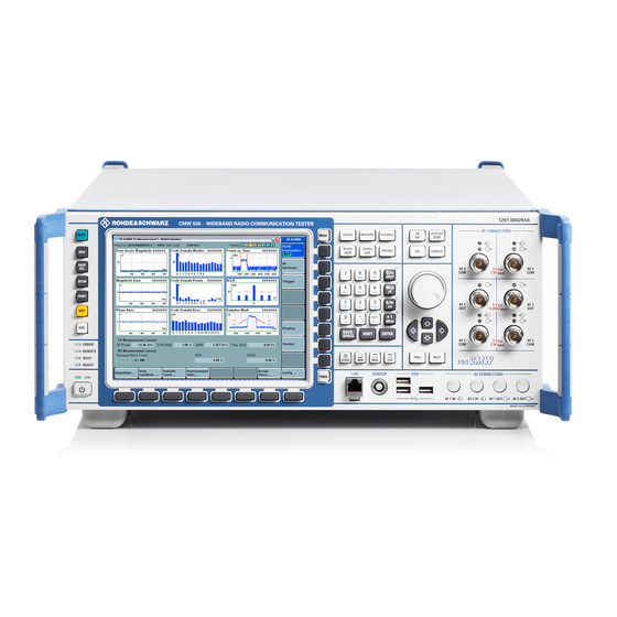
2.2.1 Front Panel Tour The front panel of the R&S CMW500 with display consists of the VGA display with the softkey and hotkey areas, the utility keys to the left, the hardkey area to the right, the RF/ AF connectors and the control interfaces. - Page 33 HELP – opens the help system. ● SYS – minimizes the R&S CMW500 software application and gives access to the Windows XP desktop and start menu (toggle function). Use the operating system level to perform system configurations and call up additional software utilities.
- Page 34 The LED blinks to indicate that the reference frequency is not locked. This happens e.g. if the R&S CMW500 is switched from internal to external reference while no external reference signal is available, or if synchronization to the reference signal is lost.
- Page 35 ® Getting Started R&S CMW500 Instrument Tour a mouse. The buttons are adapted dynamically depending on the current application and the context. ● The "hotkey bar" across the bottom of the display contains 8 hotkeys. Pressing a hotkey at the front panel has the same effect as clicking the button above the hotkey, using a mouse.
- Page 36 ® Getting Started R&S CMW500 Instrument Tour ● ON/OFF – starts a measurement from the OFF state or aborts a running measure- ment. Switches generators or signaling generators on or off and selects/clears check- boxes in dialogs (toggle function). ●...
- Page 37 ® Getting Started R&S CMW500 Instrument Tour 2.2.1.8 Rotary Knob and Navigation Keys The rotary knob, the ARROW keys and the PREV and NEXT keys are alternative control elements for data variation and navigation in the graphical user interface. ●...
- Page 38 COM connectors are bidirectional connectors. The two LEDs above a connector indicate the connector state: ● The upper LED is lit as long as the R&S CMW500 is ready to receive signals. ● The lower LED is lit as long as it transmits an RF signal.
-
Page 39: Rear Panel Tour
USB port is 500 mA. LAN Connector 8-pin connector RJ-45 used to connect the R&S CMW500 to a Local Area Network (LAN). It supports up to 100 Mbit/s. A second LAN connector labeled LAN REMOTE is available on the rear panel of the instrument. - Page 40 REF IN is a BNC input for an external reference frequency. Use this connector to synchronize the R&S CMW500 to another device. ● REF OUT 1 is a BNC output for the internal reference frequency of the R&S CMW500. Use this connector to synchronize other instruments to the tester. ●...
-
Page 41: Connecting External Devices
The maximum input levels and voltages of the input connectors at the front and rear panel must not be exceeded. 2.2.3 Connecting External Devices The equivalent USB ports on the front and rear panel of the R&S CMW500 can be used to connect a variety of devices: ●... - Page 42 To access Windows XP via a front panel with display, press the SYS key. A great variety of printer drivers is already available on the R&S CMW500. You can load updated driver versions or new drivers e.g. from a USB memory stick or from a network directory available via LAN.
-
Page 43: Trying Out The Instrument
800 x 600 pixel by each reboot. 2.3 Trying Out the Instrument This chapter helps you to get familiar with the R&S CMW500. It provides sample sessions with a generator, a measurement and a signaling application. In the sample sessions you control the instrument manually, using a mouse and key- board. - Page 44 ® Getting Started R&S CMW500 Trying Out the Instrument As a result the "General Purpose RF - Generator" dialog is opened. Fig. 2-2: General Purpose RF Generator dialog 2. Click "Routing > Connector" and select your RF output connector. In the following we assume that RF 1 COM is used.
-
Page 45: Measuring An Rf Signal
Signal", on page 27. 2. Connect a coax cable between the two RF connectors RF 1 COM and RF 2 COM at the front panel of the R&S CMW500 to ensure that the generator signal is fed to RF 2 COM. - Page 46 ® Getting Started R&S CMW500 Trying Out the Instrument 3. Open the "GPRF Meas Power" application, e.g. from the task bar (press "TASKS" to open the task bar). If the application is not present in the task bar, enable it in the "Measurement Con- troller"...
-
Page 47: Performing Signaling Measurements
® Getting Started R&S CMW500 Trying Out the Instrument 2.3.3 Performing Signaling Measurements The purpose of a signaling application is to establish a network connection to a mobile station in order to perform various tests. All signaling applications are controlled in an analogous manner. - Page 48 ® Getting Started R&S CMW500 Trying Out the Instrument 9. Press the "Connect RMC" hotkey to set up a connection. Note the connection states displayed in the main view and wait until the connection (the call) has been established. 10. Use the "Go to..." softkey to switch to the "WCDMA Multi Evaluation" measurement application.
-
Page 49: Operating The Instrument
® Getting Started R&S CMW500 Operating the Instrument 2.4 Operating the Instrument You can operate the instrument manually or via remote control: ● Remote control: You create scripts to automate repeating settings, tests and measurements. The instrument is connected to a computer that is running the program. - Page 50 ® Getting Started R&S CMW500 Operating the Instrument 2. Select the applications for which an entry shall be displayed in the task bar. 3. To close the dialog press MEASURE or ESC. Alternatively select an application at the bottom of the GUI. As a result the dialog closes and the main view of the selected application is opened.
-
Page 51: Entering Data Via Front Panel Keys
® Getting Started R&S CMW500 Operating the Instrument Together with the navigation keys and the data entry keys, softkeys and hotkeys ensure that you can access any instrument function without a mouse or an external keyboard. To use a softkey-hotkey combination proceed as follows: 1. -
Page 52: Entering Data Via An External Keyboard
® Getting Started R&S CMW500 Operating the Instrument 2. Enter/modify the number: ● Use the keys 0 to 9 to enter these digits. ● Use the UP / DOWN ARROW keys to increment/decrement a digit. ● Use the LEFT / RIGHT ARROW keys to move the cursor within the input field. -
Page 53: Using The Soft-Front Panel And Keyboard Shortcuts
® Getting Started R&S CMW500 Operating the Instrument Navigating between tabs ► Press SHIFT + TAB / TAB to switch to the previous tab to the left or to the next tab to the right. Selecting a value from a pull-down list 1. - Page 54 Operating the Instrument ● The extended soft-front panel emulates all front panel controls of an R&S CMW500 equipped with a display. It provides a graphical presentation of the front panel. A horizontal screen resolution of 1280 pixels or higher is required to display the extended soft-front panel.
-
Page 55: Administrative Tasks
"Remote Desktop" connection. 2.5.1 Windows XP The R&S CMW500 is equipped with a Windows XP operating system which has been configured according to the instrument's features and needs. Changes in the system configuration can be necessary in order to: ●... -
Page 56: Software Update
Selector.....................44 2.5.2.1 Software Packages The R&S CMW500 software consists of the mandatory CMW base software package plus optional packages for firmware applications and utilities. These packages are inte- grated in setup files named "Setup_CMW_<Scope>(Release)_<Version>.exe". For the base software package <Scope> equals BASE, resulting in the filename "Setup_CMW_BASE(Release)_<Version>.exe". - Page 57 To install a software update, follow the steps below. They apply to a complete update of all packages as well as to the update of only a selected package. 1. Shut down a running R&S CMW500 software using an external keyboard and "Alt + F4".
- Page 58 44. Tests during type approval It is not required to perform a recalibration of the R&S CMW500 after a software upgrade or downgrade. To ensure that the R&S CMW500 TX and RX is working according to the specification...
- Page 59 Fig. 2-6: R&S Software Distributor The software distributor can initiate a local or a remote installation. 1. Select "Local Installation" if you start your setup file from the R&S CMW500 hard disk or an external storage medium (USB memory stick, CD-ROM with external drive) connected to the instrument.
- Page 60 ® Getting Started R&S CMW500 Administrative Tasks Note that a remote installation also allows you to update several instruments simul- taneously. If you want to install packages contained in several setup files, proceed as follows: 1. Store all setup files in the same directory.
-
Page 61: Remote Operation In A Lan
Version Selector" until the action is finished. 2.5.3 Remote Operation in a LAN A LAN connection is used to integrate the R&S CMW500 into a home/company network or to connect it directly to another PC or instrument. This offers several applications, for example: ●... - Page 62 The use of hubs, switches, or gateways is not needed, however, data transfer is still made using the TCP/IP protocol. Avoid parallel connection Never use more than one LAN connector to connect the R&S CMW500 in parallel to the same network as this will result in connection errors. 2.5.3.2...
- Page 63 Getting Started R&S CMW500 Administrative Tasks By default, the R&S CMW500 is configured to use DHCP. This means that it is safe to establish a physical connection to the LAN without any previous R&S CMW500 configuration. ● If the network does not support DHCP, or a specific TCP/IP configuration is reques- ted, the addresses must be set manually.
-
Page 64: Maintenance
VNC. Password protection Remote access to the R&S CMW500 requires a user name and password. In the factory configuration, "instrument" is preset both for the user name and for the password. To protect the tester from unauthorized access, it is recommended to change the password. -
Page 65: Cleaning
® Getting Started R&S CMW500 Maintenance 2.6.1 Cleaning The outside of the instrument is suitably cleaned using a soft, lint-free dust cloth. Shock hazard Before cleaning the instrument, make sure that the instrument is switched off and dis- connected from all power supplies. - Page 66 ® Getting Started R&S CMW500 Maintenance Shock hazard Before replacing a fuse, make sure that the instrument is switched off and disconnected from all power supplies. Always use fuses supplied by Rohde & Schwarz as spare parts, or fuses of the same type and rating.
-
Page 67: System Overview
Generators 3 System Overview This chapter provides an overview of the capabilities of the R&S CMW500 and their use. This includes a description of the basic concepts that the tester uses to organize, process and display measurement data. These basic concepts are valid for all firmware applica- tions. -
Page 68: Rf Path Settings (Generators)
3.1.2 RF Path Settings (Generators) The R&S CMW500 provides a number of settings that are very similar in different gen- erators but can be configured independently. These settings control the routing of signals and the generator level. -
Page 69: Real-Time And Arbitrary (Arb) Generators
R&S WinIQSIM) which is loaded and processed at runtime. For details refer to the "GPRF Generator" description. The R&S CMW500 provides real-time and ARB generator signals for many network standards. Both generator types have their specific advantages. -
Page 70: Measurements
(ON/OFF or RESTART/STOP). 3.2.2 Connection Control (Measurements) The R&S CMW500 provides a number of settings that are very similar in different meas- urements but can be configured independently. These settings control the routing of input signals, the correction of the input power, the RF analyzer and trigger system. - Page 71 (gain). The external attenuation also enters into the internal calculation of the maximum input power that the R&S CMW500 can measure (see "Expected Nominal Power" below). Frequency-independent attenuations are defined as part of the measurement settings, refer to the description of the measurement application. Frequency-dependent correction tables are administrated and activated/deactivated only via remote commands (...:FDCorrection:...).
-
Page 72: Statistical Settings
Measurements generally cover a basic time interval and can be repeated periodically. The measurement interval depends on the measurement context. The number of measurement intervals that the R&S CMW500 repeats in order to calcu- late statistical results is termed "statistic count" or "statistic length" (multi-measurement count). -
Page 73: Statistical Results
3.2.4.1 Statistics Type The statistics type defines how the R&S CMW500 calculates the displayed values if the measurement extends over several measurement intervals. Assume that a trace or a bar graph contains a series of different measurement points. After n consecutive measure-... - Page 74 The statistics type of the displayed trace generally belongs to the display configuration settings in the measurement configuration dialogs. For single measurement results, the R&S CMW500 often displays a table with all statistics types. The statistics type is often combined with detector settings.
- Page 75 ® System Overview R&S CMW500 Measurements ● Minimum: The displayed result represents the minimum value in a specified mea- surement interval. Narrow peaks cannot be smoothed out due to averaging. ● Maximum: The displayed result represents the maximum value in a specified mea- surement interval.
- Page 76 Equation 1: To obtain average traces, the R&S CMW500 calculates the average of consecutive mea- surement intervals at each trace point. The formula above is modified for the magnitude error and the phase error, where positive and negative contributions tend to compensate each other.
-
Page 77: Limit Check
A limit check consists of comparing the measurement results to the limits and displaying a pass/fail indication. The R&S CMW500 provides different tools for viewing limits and limit check results. ● Limit lines show the upper, lower, or symmetric limits for a series of measurement results (measurement trace). -
Page 78: Measurement Triggers
● The meaning of a "Free Run" trigger is measurement-specific. In most cases, a "Free Run" measurement is not related to any trigger events: The R&S CMW500 measures as fast as possible. However, there are exceptions (e.g. WCDMA measurements) where "Free Run" trigger implies a synchronization to the RF input signal. -
Page 79: Tx Measurements
● The "Trigger Threshold" defines the power of the trigger signal where the R&S CMW500 generates a trigger event. Trigger signals below the trigger threshold are ignored by the trigger system. This trigger parameter is used for power trigger sources. - Page 80 The modulation parameters are acquired in a single measurement process. The calcu- lation is based on the comparison of the actual output signal Z of the transmitter under test with a reference signal R that is generated by the R&S CMW500 and represents an ideal error-free received signal.
- Page 81 ® System Overview R&S CMW500 Measurements | E | = | Z - R’ | Magnitude of the error vector, calculated at each sample in the measurement inter- val. Δ φ Phase error | Z | - | R’ |...
- Page 82 ® System Overview R&S CMW500 Measurements I/Q Offset, I/Q Imbalance, Waveform Quality The following figure is an idealized representation of the modulation errors where the effects of a pure origin offset (first diagram) and of a pure I/Q imbalance (second diagram) are completely disentangled.
- Page 83 The I/Q imbalance in dB is equal to the difference between the estimated I and Q ampli- tudes of the measured signal, which are normalized and logarithmized as follows: From the I/Q imbalance the R&S CMW500 derives the gain imbalance and quadrature mismatch as described in section "Measurement Results" in the description of the "WiMAX measurement"...
- Page 84 ACLR definition for networks like GSM and TDMA but differs from the sign convention for WCDMA (3GPP/FDD); see specification 3GPP TS 34.121. To make results comparable, the R&S CMW500 uses the GSM sign convention for all network standards.
- Page 85 ® System Overview R&S CMW500 Measurements Occupied Bandwidth (OBW) For wideband and OFDM(A) signals, the "Occupied Bandwidth" is the width of a sym- metric frequency interval around the nominal RF carrier frequency that contains 99 % of the total integrated power of the transmitted spectrum. The occupied bandwidth shows whether the signal is confined to the assigned bandwidth of the channel.
- Page 86 ® System Overview R&S CMW500 Measurements In the following figure, the CDP of the DPCCH and the DPDCH in an uplink WCDMA signal is displayed over a measurement period of 120 WCDMA slots. The average DPDCH power is approximately 1 dB above the average DPCCH power.
- Page 87 3.2.7.6 Multi Evaluation Measurements In a multi evaluation measurement, the R&S CMW500 acquires a wide range of mea- surement results at once. For example, the GSM multi evaluation measurement provides the most important GSM mobile transmitter test results described in specification 3GPP TS 51.010: ●...
-
Page 88: Rx Measurements
The purpose of an RX measurement is to assess the performance of an RF receiver. The R&S CMW500 transmits a definite bit pattern on the downlink (forward) RF signal. The device under test demodulates the received signals; the percentage of bits or data blocks received in error is counted. -
Page 89: Markers
Signaling applications provide integrated receiver quality tests. The receiver quality is assessed with an established network connection; the details are network-depend- ent. The R&S CMW500 controls the DUT such that it can either loop back the received data or send acknowledge (ACK) or not acknowledge (NACK) messages to indicate whether it could successfully receive a data packet or frame. -
Page 90: Rf Path Settings
31. 3.3.1 RF Path Settings The R&S CMW500 provides a number of settings that are very similar in different sig- naling applications but can be configured independently. These settings control the rout- ing of signals and the signal levels. -
Page 91: Connection States
The con- nection states and state transitions are network-specific; refer to the description of the individual signaling application. When the connection is established, the R&S CMW500 is ready to perform signaling tests. User Manual 1173.9463.02 ─ 06... -
Page 92: Sub-Instruments
® System Overview R&S CMW500 Sub-Instruments 3.4 Sub-Instruments An instrument with several RX and TX signal paths can either be used as one (sub-)instru- ment or it can be split into several sub-instruments which operate independently. This section provides basic information related to both modes. -
Page 93: Two Sub-Instruments
® System Overview R&S CMW500 Sub-Instruments Table 3-3: Accessible RX/TX modules depending on baseband link Instance 1 Instance 2 Flexible link RX 1, RX 2, TX 1, TX 2 RX 1, RX 2, TX 1, TX 2 Fixed link RX 1, TX 1... - Page 94 ® System Overview R&S CMW500 Sub-Instruments Table 3-4: Assignments for two sub-instruments Sub-instrument 1 Sub-instrument 2 Generator Controller entry "GPRF Generator" "GPRF Generator" Measurement Controller entry "GPRF Power" "GPRF Power" Remote commands ...:GPRF:GEN:..:GPRF:GEN:..:GPRF:MEAS:POW:..:GPRF:MEAS:POW:... Assigned Instrument = 1...
-
Page 95: Basic Instrument Functions
The "Startup" dialog provides the following control softkeys that you can activate while the startup is in progress. Firmware Update Copies new firmware-specific data to the internal hardware of the R&S CMW500. This is required for example after a board change. User Manual 1173.9463.02 ─ 06... -
Page 96: Reset Dialog
4.4.4, "SW/HW Equip- ment", on page 90. Abort Aborts the startup procedure. The R&S CMW500 returns to standby state. Press the standby key on the front panel to re-initialize the startup. See also c hapter 2.2.1.3, "Standby Key", on page 18. - Page 97 Fig. 4-2: Dialog for 1 sub-instrument Fig. 4-3: Dialog for several sub-instruments The reset/preset can be performed for the entire R&S CMW500 or it can be limited to the current firmware application. If the R&S CMW500 has been split into sub-instruments, the reset/preset can also be limited to the current sub-instrument.
-
Page 98: Save/Recall Dialog
The R&S CMW500 uses short statistics cycles (for benchmarks). ● In multi evaluation measurements, some time-consuming evaluations are skipped to gain measurement speed. The following R&S CMW500 settings are not affected by a reset: ● Address information assigned to the instrument (e.g. the IP address) ●... - Page 99 ® Basic Instrument Functions R&S CMW500 Save/Recall Dialog Fig. 4-4: Save/Recall dialog The "Save/Recall" dialog provides the following control softkeys and hotkeys. Save / Partial Save Saves the current configuration (or a part of it) to a file. Save files are stored in a default directory on drive D: of the internal hard disk.
-
Page 100: Setup Dialog
® Basic Instrument Functions R&S CMW500 Setup Dialog "Partial Recall" opens a dialog for selection of the information to be recalled. For a description of selectable parts see " Show content" on page 84. Remote command: M MEMory: R CL... -
Page 101: System Settings
® Basic Instrument Functions R&S CMW500 Setup Dialog 4.4.1 System Settings The "System" section of the "Setup" dialog defines the overall appearance of the dialogs, address information for remote control and settings for remote software update. It also provides access to a configuration dialog of the data application unit (if installed). -
Page 102: Remote Settings
If a Data Application Unit (DAU) is installed, "Go to config" opens the "Data Application Control" dialog which lets you configure data testing IP services of the DAU. For more details, refer to the description of the "Data Application Unit". The DAU is only available for R&S CMW500. Remote command: Software Update The "Device Group"... - Page 103 ® Basic Instrument Functions R&S CMW500 Setup Dialog Fig. 4-6: Setup - Remote Most connection parameters are fixed and displayed for information only. The most important parameters are described below. Visa Resource (all protocol types) The "Visa Resource" string depends on the protocol type and the assigned address information.
- Page 104 ® Basic Instrument Functions R&S CMW500 Setup Dialog For VXI-11 and HiSLIP the "Assigned Instrument" number is also part of the VISA resource string, with instrument 1 mapped to "inst0" and instrument 2 mapped to "inst1". Remote command: Data Port (TCPIP only) The data port number is part of the TCPIP VISA resource string.
-
Page 105: Activating Options
S YSTem: C OMMunicate: G PIB<i>[: S ELF]: E NABle 4.4.3 Activating Options New R&S CMW500 options must be enabled using the key code supplied by Rohde & Schwarz. Activating a previously installed option involves the following steps: 1. Open the "License Keys" section in the "Setup" dialog. -
Page 106: Sw/Hw Equipment
USB memory stick. 4.4.4 SW/HW Equipment The "SW/HW Equipment" section of the "Setup" dialog shows the software and hardware that is installed on your R&S CMW500 and lists the available options. Fig. 4-8: Setup - Remote User Manual 1173.9463.02 ─ 06... -
Page 107: Selftests
S YSTem: B ASE: O PTion: V ERSion? 4.4.5 Selftests The R&S CMW500 provides extensive selftest procedures on module and system level. The selftests are primarily intended for production and service purposes; they are not needed during normal operation of the instrument. The following description serves as a general overview. - Page 108 A diagnoses test is provided for most of the R&S CMW500 modules. RAM Test The R&S CMW500 tests one or more of the memories (SRAM, SSRAM, ASRAM, DDR) on the board. Two different types of memory tests are provided. ●...
- Page 109 Download Test The R&S CMW500 loads program data into a DSP or FPGA module and verifies that the module responds properly. EEprom Test The R&S CMW500 verifies that the I2C EEprom data of the board is well-formed (i.e.
- Page 110 Sample Bus Test A pseudo-random bit sequence (PRBS) is transferred over the sample bus between two hardware modules. The R&S CMW500 compares the transmitted PRBS with the received PRBS and verifies that no bit errors occur in the transmission path.
- Page 111 "Lan Remote" network adapter; see c hapter 4.4.9, "IP Subnet Configuration", on page 101. When the test is started, the R&S CMW500 prompts for the appropriate cable connection, e.g.: A similar message ("Please disconnect...") is displayed after the test is finished. 4.4.5.4 Performing Selftests Selftests are controlled like any other measurement.
- Page 112 "Halt on Failure". ● In "Continuous" mode all selected selftests are repeated until the selftest is explicitly aborted; the results are updated after each test cycle: The R&S CMW500 performs a long-term test. ● A "Single Shot" measurement is stopped after all selected tests have been comple- ted.
-
Page 113: Sync Settings
Selects all or a current group (subtree) of selftests for execution or clears the current selection. 4.4.6 Sync Settings The R&S CMW500 can be synchronized either to its fixed internal reference frequency or to an external reference. For multi-CMW setups a system synchronization signal has to be provided by one instru- ment to the other instruments of the setup. - Page 114 S ENSe: B ASE: R EFerence: F REQuency: L OCKed? SYS SYNC This setting is only present if the R&S CMW500 is equipped with a "Multibox Flexible Link Sample Bus Board with external SysSync Support" (option R&S CMW-S550M). The parameter specifies the mode of system time synchronization. It is essential when switching between single-CMW and multi-CMW setups.
-
Page 115: Trigger
The bidirectional BNC connectors TRIG A and TRIG B support input and output trigger signals: ● An input trigger signal is used to synchronize an R&S CMW500 measurement to an external event. For example a DUT providing a frame-periodic RF signal may gen- erate an additional trigger signal to indicate its frame timing. -
Page 116: Logging
® Basic Instrument Functions R&S CMW500 Setup Dialog Slope ← TRIG A, TRIG B Slope to be used for output trigger signals. The trigger event can either be marked by a rising edge or by a falling edge. Remote command: ... -
Page 117: Ip Subnet Configuration
● Adapter ID, identifying a network adapter within a subnet node. Some applications provided by the R&S CMW500 require that you establish a direct connection between the LAN REMOTE connector and the LAN SWITCH and assign a specific IP address to the "Lan Remote" network adapter. To do so, plug the patch cable delivered with option R&S CMW-B661 into the LAN REMOTE connector and connector... - Page 118 ® Basic Instrument Functions R&S CMW500 Setup Dialog The elements of the subnet configuration dialog are described below. Fig. 4-14: Setup - Misc - IP Subnet Configuration Subnet Node This section configures the internal IPv4 subnet of the instrument. Node Name ← Subnet Node Displays the fixed name assigned to the subnet node, i.e.
- Page 119 List of all nodes detected in the subnet, including the instrument itself. The list indicates the name, the type, the ID and the description of each node. For the R&S CMW500 this information corresponds to the values in section ...
-
Page 120: Digital Iq
CMW500 Setup Dialog 4.4.10 Digital IQ The "Digital IQ" section is only present if the R&S CMW500 is equipped with an I/Q board (option R&S CMW-B510x/-B520x). The settings are not relevant for "external fading" scenarios of signaling applications. But they apply for example to "IQ out - RF in" scenarios. -
Page 121: Print Dialog
C ONFigure: B ASE: F CONtrol 4.5 Print Dialog The "Print" dialog prints the current R&S CMW500 window to a file, to be saved on par- tition D: of the internal hard disk or a USB memory stick. Other elements besides the R&S CMW500 window are not captured (e.g. -
Page 122: Info Dialog
CMW500 Info Dialog Fig. 4-17: Print dialog The R&S CMW500 supports the following bitmap data formats for print files: ● .bmp, .emf, .jpeg, .pbm, .pgm, .png, .ppm, .wmf, .xbm, .xpm The default file format (for file names entered without extension) is .jpeg. - Page 123 ® Basic Instrument Functions R&S CMW500 Info Dialog Fig. 4-18: Info – Current State State Generator state, signaling generator state or measurement state, see G enerator Con- trol, and M easurement Control C ontrol of the Cell State.
-
Page 124: Problem Reporting
® Basic Instrument Functions R&S CMW500 Info Dialog OS Settings Displays the most important address settings for remote control. For configuration see chapter 4.4.1, "System Settings", on page 85. Latest Correction Displays the type and date of the last correction of the instrument. Remote commands allow also to query information about previous corrections. - Page 125 ® Basic Instrument Functions R&S CMW500 Info Dialog Fig. 4-19: Info – Problem Reporting The dialog provides the following hotkeys. Prepare for sending Stores the selected log file directory into one or more compressed files, located in the "Output" directory.
-
Page 126: Instrument Setup Dialog
® Basic Instrument Functions R&S CMW500 Instrument Setup Dialog 4.7 Instrument Setup Dialog The "Instrument Setup" dialog is only relevant for instruments with several RX and TX signal paths. These instruments are equipped with six RF connectors at the front panel, while instruments with one path provide only three RF connectors. -
Page 127: Measurement Controller Dialog
® Basic Instrument Functions R&S CMW500 Measurement Controller Dialog 4.8 Measurement Controller Dialog The "Measurement Controller" dialog lists the available measurement firmware applica- tions and allows to add measurement applications to the task bar. To open the dialog press the MEASURE key at the (soft-)front panel. -
Page 128: Blockview Dialog
® Basic Instrument Functions R&S CMW500 Blockview Dialog 4.10 Blockview Dialog The "Blockview" dialog provides an overview of the configured signal routing settings. It allows to: ● display the current allocation of signal path resources to firmware applications ● display the signal path configured for a firmware application ●... -
Page 129: Show Active Routing
® Basic Instrument Functions R&S CMW500 Blockview Dialog Each block provides the graphical presentation of an LED, indicating the state of the displayed firmware application. A yellow LED indicates "RUN" or "ON", a green LED indicates "RDY" and a red LED indicates started ("RUN") but error occurred (e.g. - Page 130 ® Basic Instrument Functions R&S CMW500 Blockview Dialog Fig. 4-24: Blockview dialog - Selectable Routing Note that each drop-down menu to the left lists only the installed firmware applications supported by the block. The first (uppermost) "BB Generator" supports the first instance of generator applications, the second "BB Generator"...
-
Page 131: System Messages
4.11 System Messages System messages give information about exceptional states of the instrument. If possible, the messages also describe necessary user interactions. The R&S CMW500 uses dif- ferent types of messages, depending on the source and nature of the described situation. - Page 132 Fig. 4-27: System warning System Error Message System error messages are displayed when the R&S CMW500 software needs to be restarted to continue operation. In general the message box describes the cause of the exception and contains two buttons to shutdown or restart the software.
-
Page 133: Remote Control
® Remote Control R&S CMW500 Remote Control Operation 5 Remote Control This chapter provides instructions on how to set up the tester for remote control, a general introduction to remote control of programmable instruments, and the description of the tester's remote control concept. - Page 134 2733 (0xAAD) is the manufacturer ID of Rohde & Schwarz 87 (0x57) is the R&S CMW500 model code The serial number is device-specific. GPIB "GPIB[board]::primary address[::INSTR]" Two optional GPIB bus interfaces according to stand- ard IEC 625.1/IEEE 488.1 (options R&S CMW-B612A...
-
Page 135: Drivers For Graphical Programming Interfaces
The drivers are available for download from http://www.rohde-schwarz.com. 5.1.2 Establishing and Testing a LAN Connection In the following example, a direct LAN connection is set up to the R&S CMW500. The connection is tested using a simple test script. -
Page 136: Switching Between Manual And Remote Control
Hostname and IP address The VISA address strings displayed in the "Setup" dialog contain the hostname of the R&S CMW500 instead of the IP address. Use the address string type that is most con- venient for you. The following test script queries the identification string of the connected R&S CMW500... - Page 137 5.1.3.2 Returning to Manual Operation The R&S CMW500 switches back to manual operation when the remote connection is closed. Besides, return to manual operation can be initiated manually via hotkey or via remote control: ●...
-
Page 138: Monitoring The Remote Control Interface
® Remote Control R&S CMW500 Remote Control Operation ● Via VXI-11 protocol: &LLO interface message ● Many instrument driver commands, e.g. the NI commands SetRWLS (Set Remote With Lockout State) or SendLLO, also contain a local lockout command. In the local lockout state an unintentional return to manual control is not possible. All "Go To Local"... -
Page 139: Multiple Channels For Remote Access
Remote Control Operation 5.1.5 Multiple Channels for Remote Access Several remote channels can be used simultaneously. The R&S CMW500 supports up to four parallel channels. No restriction is placed upon the combination of channels: It is possible to combine several channels of the same type (e.g. two LAN channels), or channels of different types (e.g. -
Page 140: Messages
R&S CMW500 to initiate a service request (SRQ) are also channel-specific. 5.2 Messages The messages transferred between the controller and the R&S CMW500 can be either interface messages or device messages. The general structure of the device messages is defined by the SCPI standard. For spe- cific features of the R&S CMW500 command set refer to section ... -
Page 141: Scpi Command Structure And Syntax
® Remote Control R&S CMW500 Messages are messages the instrument sends to the controller after a query. They can contain measurement results, instrument settings and information on the instrument status. Commands are subdivided according to two criteria: 1. According to the effect they have on the instrument: ●... - Page 142 ® Remote Control R&S CMW500 Messages Command Description *RST RESET, resets the sub-instrument. *ESE 253 EVENT STATUS ENABLE, sets the bits of the event status enable registers. *IDN? IDENTIFICATION QUERY, queries the instrument identification string. 5.2.4.2 Instrument-Control Commands Instrument-control commands are based on a hierarchical structure and can be repre- sented in a command tree.
- Page 143 The key words have a long form and a short form. The short form consists of all upper- case characters, the long form of all upper case plus all lower case characters. The R&S CMW500 recognizes both the short form and the long form. Example:...
- Page 144 Symbols in angular brackets (<ch>, <i>, <n>,...) denote numeric suffixes. Numeric suf- fixes have to be replaced by integer numbers to distinguish various items of the same type. The R&S CMW500 provides numeric suffixes for firmware application instances, signal sources etc. If unspecified, a numeric suffix is replaced by 1.
- Page 145 ® Remote Control R&S CMW500 Messages the semicolon starts with the level that lies below the common levels. The colon following the semicolon must be omitted in this case. Example: SOURce:GPRF:GENerator:RFSettings:FREQuency 1GHz; :SOURce:GPRF: GENerator:RFSettings:LEVel -80 This command line is written in its full length and contains two commands separated from each other by the semicolon.
- Page 146 Unless it is explicitly stated in the command description you can use the special numeric parameters described above for all commands of the R&S CMW500. Other special parameters are generally not supported.
- Page 147 ® Remote Control R&S CMW500 Messages Example: Setting command: SOURce:GPRF:GENerator:STATe ON Query: SOURce:GPRF:GENerator:STATe? returns ON Some of the remote control commands in the SYSTem... and STATus... subsystems are not implemented as described above. These commands are not needed to perform measurements or generate RF signals.
-
Page 148: R&S Cmw Command Structure
5.3 R&S CMW Command Structure The syntax of the remote commands for the R&S CMW500 reflects the instrument's basic software modules. The header of each instrument-control command contains the logical software entity the command is assigned to, eliminating the need of addressing the enti- ties (e.g. -
Page 149: Firmware Applications
M easurement Contexts Views. They are identified by fourth- and fifth/sixth-level mnemonics. Due to the general structure described above, most R&S CMW500 commands are not SCPI confirmed, however, they follow SCPI syntax rules (see also R emote Control Oper- ation). - Page 150 Structure. A possible numeric suffix <i> (short for <instance>) behind the FWA mnemonics distinguishes several FWAs of the same type. See also ub-Instruments. The following table provides examples of FWAs of the R&S CMW500 and their mne- monics: Firmware Application Description BLUetooth:MEASurement<i>...
-
Page 151: Measurement Contexts And Views
® Remote Control R&S CMW500 Control of the Instrument 5.3.3 Measurement Contexts and Views Most measurement F irmware Applications are further subdivided into different measure- ment contexts. In manual control, a measurement context may consist of several views, providing different types of measurement results. In remote control, measurement con- texts and views are identified by the fourth- and fifth/sixth-level mnemonics in the com- mand headers, respectively. -
Page 152: Generator Control
R&S CMW500 Control of the Instrument 5.4.1 Generator Control The commands used to control the different RF signal generators of the R&S CMW500 are analogous to the commands explained in section M easurement Control. A generator is in one of the following generator states: ●... -
Page 153: Measurement Control
5.4.2 Measurement Control The R&S CMW500 provides a variety of measurements (also termed measurement con- texts) for each of the supported network standards or general purpose applications. All measurements are identified by a fourth level mnemonic and controlled in an analogous way. - Page 154 ® Remote Control R&S CMW500 Control of the Instrument ● RDY: Measurement has been terminated, valid results may be available. RDY cor- responds to the SCPI trigger state IDLE. ● RUN: Measurement running (after INITiate..., READ...), synchronization pending or adjusted, resources active or queued (see ...
- Page 155 STOP:<Application>:MEASurement<i> Halts the measurement immediately. The measurement enters the RDY state; the R&S CMW500 retains all valid measurement results. Moreover, the hardware and system resources continue to be allocated to the measurement. User Manual 1173.9463.02 ─ 06...
- Page 156 Measurements generally cover a basic time interval and can be repeated periodically. The measurement interval depends on the measurement context. The number of measurement intervals that the R&S CMW500 repeats in order to calcu- late statistical results is termed "statistic count" (multi-measurement count). After one statistic count, the instrument has terminated a basic measurement cycle ("single-shot"...
- Page 157 ® Remote Control R&S CMW500 Control of the Instrument Repetition Mode Single-shot: The measurement is stopped after the number of measurement intervals defined by the "statistic count". Continuous: The measurement is continued until it is stopped explicitly. Average results are calculated according to the rules given in section ...
- Page 158 A FETCh...? command can be used in the RUN state as described above or in the RDY state, provided that the R&S CMW500 has stored valid results. If no valid results are available, NCAP, NAV or INV are returned for each unavailable valid result, see also ...
- Page 159 In continuous mode, the first FETCh...? is executed after the end of the current measurement cycle. The following FETCh...? commands are executed as quickly as possible, no matter whether the R&S CMW500 has acquired new results. READ...? Command Aborts the current measurement (if a measurement is running), starts a new measure- ment in single-shot mode, and returns the results including the ...
- Page 160 ® Remote Control R&S CMW500 Control of the Instrument Performance considerations, multi evaluation measurements The READ...? query is view-specific and calculates only the results needed for a par- ticular view. This can result in a performance improvement compared to the context- specific command sequence INITiate...;...
- Page 161 Measurements. 5.4.2.5 Multi Evaluation Measurements In a multi evaluation measurement, the R&S CMW500 acquires a wide range of mea- surement results at once. For example, the GSM multi evaluation measurement provides the most important GSM mobile transmitter test results described in specification 3GPP TS 51.010: ●...
-
Page 162: Signaling Generator Control
® Remote Control R&S CMW500 Control of the Instrument each multi evaluation measurement as a whole but retrieve the different types of results separately. Controlling multi evaluation measurements A multi evaluation measurement is controlled like any other measurement; see ... - Page 163 ® Remote Control R&S CMW500 Control of the Instrument "Generator Control", on page 136. A signaling generator is in one of the following cell states: ● OFF: Signaling generator turned off, resources either released or (partially) reserved from the last time the generator was turned on.
-
Page 164: Reliability And Error Indicators
® Remote Control R&S CMW500 Control of the Instrument SOURce:<Application>:SIGNaling<i>:CELL:STATe ON Starts the signaling generator, reserves all necessary hardware and system resources and changes to the generator state "PENDing", then "ON". If the cell signal is already turned on the command has no effect. - Page 165 Reliability Indicator Reliability indicators are provided by all types of applications, including measurements, generators and signaling applications. The R&S CMW500 returns a numerical reliability indicator value for each measurement result query. This indicator value allows to judge the reliability of the returned measurement results.
- Page 166 17 (RF Level not Settled) / 18 (RF Frequency not Settled): The measurement could not be started because the R&S CMW500 was not yet ready to deliver stable results after a change of the input signal power / the input signal frequency.
- Page 167 ® Remote Control R&S CMW500 Control of the Instrument The current DAU configuration by the user is incomplete or wrong and could not be applied. Check especially the IP address configuration. ● 54 (Filesystem Error): The hard disk of the DAU is full or corrupt. Please execute a DAU selftest.
-
Page 168: Signal Path Settings
® Remote Control R&S CMW500 Control of the Instrument Returned value Meaning Description Overflow Measurement result available, however, the accuracy of the result may be impaired because the input signal level was too high Underflow Measurement result available, however, the accuracy of the... - Page 169 ® Remote Control R&S CMW500 Control of the Instrument ROUTe commands changed in V2.0.10 Routing commands of the type ROUTe:<Application>:<Instance>:RFSettings:CONNector are no longer supported for software versions ≥ V2.0.10. The old routing commands select only an RF connector but no RX/TX module and must no longer be used.
- Page 170 ® Remote Control R&S CMW500 Control of the Instrument You may also use the following rules and the subsequent sections to determine the sup- ported signal paths: ● One frontend provides three RF connectors at the front panel: either RF 1 COM + RF 1 OUT + RF 2 COM or RF 3 COM + RF 3 OUT + RF 4 COM.
- Page 171 ® Remote Control R&S CMW500 Control of the Instrument – The number of active software licenses limits the number of instances that can be run in parallel. 5.4.5.2 RF Connector Values The following list contains all parameter values generally available for selection of an RF connector.
- Page 172 ® Remote Control R&S CMW500 Control of the Instrument All instances can access both frontends. The following table lists the supported parameter values and used *RST values for selection of RF connectors and TX/RX boards. Instance 1 Instance 2 Input connector...
- Page 173 ® Remote Control R&S CMW500 Control of the Instrument Each sub-instrument uses one specific frontend and supports one instance per firmware application. The TX and RX module numbering is a logical numbering per sub-instrument, not per instrument. That means e.g. that within sub-instrument 1 the value TX1 refers to another physical TX module than within sub-instrument 2.
- Page 174 ® Remote Control R&S CMW500 Control of the Instrument sub-instrument, not per instrument. That means e.g. that within sub-instrument 1 the value TX1 refers to another physical TX module than within sub-instrument 2. The following table lists the supported parameter values and used *RST values for selec- tion of RF connectors and TX/RX boards.
-
Page 175: Resource And Path Management
TX1, RX1 TX2, RX2 5.4.6 Resource and Path Management The R&S CMW500 is a modular platform supporting a wide range of measurement, gen- erator, and signaling applications. For the remainder of this section, all these applications are termed "tasks". In general, the instrument is capable of running several tasks in parallel. E.g. the GPRF... - Page 176 R&S CMW500 Control of the Instrument 5.4.6.1 Basic RPM Principles The principles of R&S CMW500 Resource and Path Management can be summarized very briefly: ● Non-conflicting tasks can run in parallel without restriction. ● A new measurement or generator that is in conflict with a running task replaces the running task.
- Page 177 Two non-conflicting measurements, executed in parallel RPM acts on sub-instrument level If the R&S CMW500 is split into several sub-instruments, each of them is equipped with independent hardware and software resources in order to run the tasks assigned to it.
- Page 178 ® Remote Control R&S CMW500 Control of the Instrument Command Comment FETCh:<FWA>:<Meas1>...CURRent? Wait until the end of the statistics cycle of measurement 1 and retrieve the results. (or similar command syntax for reading measurement results) FETCh:<FWA>:<Meas2>:STATe:ALL? Query the measurement substates of measurement 2. The response (RUN, ADJ, ACT) indicates that measurement 2 is now active.
- Page 179 I/Q data lines etc.) Software license key conflicts Many R&S CMW500 features must be enabled using a software license key. To be run in parallel, several measurements of the same type may require several active software license keys. A resource conflict arises whenever the required number of software options is not available.
-
Page 180: Command Processing
® Remote Control R&S CMW500 Command Processing 5.5 Command Processing The block diagram below shows how remote commands are serviced in the instrument. The individual components work independently and simultaneously. They communicate with each other by means of so-called "messages". -
Page 181: Command Recognition
® Remote Control R&S CMW500 Command Processing during command recognition and execution. The receipt of a DCL clears the input buffer and immediately initiates a message to the command recognition. 5.5.2 Command Recognition The command recognition stage analyzes the data received from the input unit. It pro- ceeds in the order in which it receives the data. -
Page 182: Status Reporting System
® Remote Control R&S CMW500 Status Reporting System 5.5.4 Status Reporting System The status reporting system collects information on the instrument state and makes it available to the output unit on request. The exact structure and function are described in section ... -
Page 183: Overview Of Status Registers
ESR. 5.6.1 Overview of Status Registers The status registers of the R&S CMW500 are implemented as shown below. 5.6.2 Structure of an SCPI Status Register Each standard SCPI register consists of 5 parts which each have a width of 16 bits and have different functions. - Page 184 ® Remote Control R&S CMW500 Status Reporting System significant bit) is set to zero for all parts. Thus the contents of the register parts can be processed by the controller as positive integer. The sum bit is obtained from the EVENt and ENABle part for each register. The result is then entered into a bit of the CONDition part of the higher-order register.
-
Page 185: Contents Of The Status Registers
® Remote Control R&S CMW500 Status Reporting System ● NTR bit = 1: the EVENt bit is set. ● NTR bit = 0: the EVENt bit is not set. This part can be overwritten and read at will. Reading the PTRansition register is non- destructive. - Page 186 ® Remote Control R&S CMW500 Status Reporting System The STatus Byte (STB) is linked to the Service Request Enable (SRE) register on a bit- by-bit basis. ● The STB corresponds to the EVENt part of an SCPI register, it indicates general instrument events.
- Page 187 ® Remote Control R&S CMW500 Status Reporting System bit 6 being used as well in contrast to the SRE. The IST flag results from the ORing of all results. Related common commands The IST flag is queried using the command *IST?.
- Page 188 ® Remote Control R&S CMW500 Status Reporting System Bit No. Meaning User Request This bit is set on pressing the LOCAL key, i. e. when the instrument is switched over to manual control. Power On (supply voltage on) This bit is set when the instrument is switched on.
- Page 189 ® Remote Control R&S CMW500 Status Reporting System Fig. 5-1: STATus:OPERation register hierarchy Each single status register in the figure above consists of five parts as described in section S tructure of an SCPI Status Register. The following simplified presentation is used:...
- Page 190 ® Remote Control R&S CMW500 Status Reporting System Fig. 5-2: Legend for figure above The following table lists the assignment of network standards (and GPRF, DAU) to the bits of the register STATus:OPERation:TASK:A. The mnemonics used to indicate the network standards are identical to the mnemonics used in remote commands (see ...
- Page 191 ® Remote Control R&S CMW500 Status Reporting System Generator function groups contain only one application which is not explicitly identified in remote commands. For the status register of this application the mnemonic UNIVersal is used (e.g. STATus:OPERation:TASK:A:GPRF:GENerator1:UNIVersal). Table 5-3: Bit definition for function group registers Bit No.
-
Page 192: Application Of The Status Reporting System
The STATus:QUEStionable register indicates whether the data currently being acquired is of questionable quality. The R&S CMW500 does not use the STATus:QUEStionable register. 5.6.4 Application of the Status Reporting System The purpose of the status reporting system is to monitor the status of one or several devices in a measuring system. - Page 193 ® Remote Control R&S CMW500 Status Reporting System The ENABle parts of the status registers can be set such that arbitrary bits in an arbitrary status register initiate an SRQ. To use the possibilities of the service request effectively, all bits in the enable registers SRE and ESE should be set to "1".
- Page 194 ® Remote Control R&S CMW500 Status Reporting System 5.6.4.2 Serial Poll In a serial poll, the controller queries the STatus Bytes of the devices in the bus system one after another. The query is made via interface messages, so it is faster than a poll by means of *STB?.
-
Page 195: Reset Values Of The Status Reporting System
5.6.5 Reset Values of the Status Reporting System The table below indicates the effects of various commands upon the status reporting system of the R&S CMW500. Event Switching on sup-... -
Page 196: Regular Expressions
® Remote Control R&S CMW500 Status Reporting System Event Switching on sup- DCL, SDC *RST or STA- *CLS ply voltage (Device Tus:PRE- SYS- Power-On-Status- Clear, Tem:PRE- Clear Selected Set:ALL Device Clear) Clear output buffer Clear command processing and input buffer 1) Every command being the first in a command line, i.e. -
Page 197: Command Macros
A macro is a sequence of remote commands which can be referenced in a remote control program. Macros are kept in the R&S CMW500's RAM while a remote connection is active; therefore they are a means of saving transfer time and speed up the measure- ment. -
Page 198: Macro Contents And Macro Commands
Memory size The block data size of any single macro (and the size of a macro file) must not exceed 1 MB. The R&S CMW500 can process macros with a combined size of up to 16 MB. 5.7.2 Macro Programming Examples The following examples show you how to use macros, macro parameters, and macro files. - Page 199 ® Remote Control R&S CMW500 Command Macros // Execute the macro. // Check whether the generator frequency has actually been changed. // ***************************************************************************** SOURce:GPRF:GENerator:RFSettings:FREQuency? *EMC ON SetFrequency SOURce:GPRF:GENerator:RFSettings:FREQuency? // ***************************************************************************** // Delete the macro. // Delete all macros in the active connection.
-
Page 200: Response Buffers
*GMC? 'RF_Settings1' 5.8 Response Buffers A response buffer is a region of memory in the R&S CMW500's RAM used to store device responses, in particular measurement data, which the R&S CMW500 generates while executing queries. If no buffer is enabled, a query in a remote script suspends program execution until the controller has retrieved the response. -
Page 201: Buffer Contents And Buffer Commands
It is possible to define several buffers, however, only one buffer can be active at any time. When a response buffer is active, the complete contents of the R&S CMW500's output buffer are copied to the active buffer instead of being transferred over the remote inter- face. -
Page 202: Lxi Configuration
® Remote Control R&S CMW500 LXI Configuration Query_macro 1 GHz FETCh:BASE:BUFFer:LINEcount? 'Frequency_Buffer' // Re-activate the buffer to appended further lines. // The line count query returns 4. CONTinue:BASE:BUFFer 'Frequency_Buffer' Query_macro 4 GHz STOP:BASE:BUFFer FETCh:BASE:BUFFer:LINEcount? 'Frequency_Buffer' // Clear the buffer contents: the line count query returns 0 // Delete the buffer: the line count query times out and the error queue // contains an entry with code -273 "Illegal macro label"... -
Page 203: Lxi Browser Interface
The R&S CMW500 supports some LXI class C features, but it is not LXI class C compliant (e.g. LCI mechanism not implemented). In addition to general class C features, it provides additional functionality, e.g. - Page 204 ® Remote Control R&S CMW500 LXI Configuration The instrument home page displays the device information required by the LXI standard including the VISA resource string in read-only format. The navigation pane of the browser interface contains the following elements: ●...
-
Page 205: Lan Configuration
® Remote Control R&S CMW500 LXI Configuration – "File Upload" allows to upload files to the instrument. – "Web Control" provides remote access to the instrument via VNC. Enter "VNC" both as user name and as password. ● "License Manager"... - Page 206 ® Remote Control R&S CMW500 LXI Configuration Password protection Changing the LAN configuration is password-protected. The password reads LxiWe- bIfc (notice upper and lower case characters). This password cannot be changed in the current software version. 5.9.3.2 Advanced Config The navigation entry "Advanced Config" provides access to additional LAN parameters that are not declared mandatory by the LXI standard.
-
Page 207: Scpi Remote Trace
5.9.4 SCPI Remote Trace The remote trace functionality allows to trace input and output strings at the remote con- trol interface of the R&S CMW500. A recorded trace (message log) can be evaluated directly in the dialog. Use the high- lighting and navigation functions provided by the lower toolbar to locate error messages and messages containing arbitrary search strings. - Page 208 ® Remote Control R&S CMW500 LXI Configuration Toolbars The toolbar at the top of the dialog provides basic settings and functions. ● live mode / logging: If logging is switched on, messages are traced. They are stored in an internal database and can be displayed upon request, using the refresh button (live mode off) or they can be displayed automatically (live mode on).
- Page 209 ® Remote Control R&S CMW500 LXI Configuration gle to scroll through the message log. The position of certain messages is indicated by colored bars: – red bar: indicates an error message – orange bar: indicates an error message containing the search string –...
-
Page 210: Command Reference - Base Software
"*" followed by three letters. Many common commands are related to the status reporting system. Some of the commands in the following list are R&S CMW500-specific but use the same syntax as common commands. They are marked "not IEEE 488.2-confirmed". - Page 211 Alternatively *XESR? can be used to return the result as comma separated list of mnemonics enclosed in brackets. For values see *XESE. *IDN? – IDentifica- – Queries the instrument identification string of the R&S CMW500. tion Query query only *IST? – Individual –...
-
Page 212: Emulation Codes
® Command Reference - Base Software R&S CMW500 Emulation Codes Command Parameters/ Short Description Remarks *SAV – SAVe 0...99 Stores the current instrument settings under the specified num- ber in an intermediate memory. The settings can be recalled no query, not IEEE using the command *RCL with the associated number. -
Page 213: Instrument-Control Commands
Starts a serial poll. 6.3 Instrument-Control Commands The instrument-control commands for the R&S CMW500 platform give access to the mass memory, control the status structures, and perform various administrative tasks. The platform commands are divided into the command groups listed below. - Page 214 The *RST state of *EMC is OFF. Macro execution must be enabled deliberately for every remote connection. ● Normal remote control execution has priority over macro execution. Macros which have the same name as a remote command supported by the R&S CMW500 are ignored..........................198 *DMC...
- Page 215 Parameters: <Boolean> Boolean value to enable or disable macro execution. In the disa- bled ("OFF") state, macros in a command sequence are not expanded. The R&S CMW500 will generally issue an error mes- sage –113, "Undefined header;<MacroLabel>". *RST: See ...
- Page 216 M MEMory: S TORe: M ACRo Note: Avoid using macro labels which are identical with any of the remote control com- mands supported by the R&S CMW500. In contrast to SCPI specifications, remote com- mands have priority over macros. Parameters: '<MacroLabel>'...
-
Page 217: Buffer Commands
Event Firmware/Software: V2.1.10 6.3.2 Buffer Commands The following remote control commands are related to response buffers. The command syntax follows the general R&S CMW500 syntax rules; the commands are not SCPI confirmed......................202 CLEar: B ASE: B UFFer ....................202 CONTinue:... - Page 218 CONTinue:BASE:BUFFer '<BufferLabel>' Re-activates a buffer which was intermediately de-activated ( ) . The S TOP: B ASE: B UFFer R&S CMW500 will continue writing data to the buffer. Parameters: '<BufferLabel>' String parameter, used to identify the buffer in all buffer commands See ...
- Page 219 ® Command Reference - Base Software R&S CMW500 Instrument-Control Commands Return values: <LineContents> Returned line contents See Example: B uffer Programming Example Usage: Query only Firmware/Software: V2.1.10 FETCh:BASE:BUFFer:LINecount? '<BufferLabel>' Returns the size (number of lines) of a buffer. Query parameters: '<BufferLabel>'...
-
Page 220: High Resolution Timer
® Command Reference - Base Software R&S CMW500 Instrument-Control Commands 6.3.3 High Resolution Timer After execution of a command it may be required to wait a well defined time before pro- ceeding with command script processing, e.g. because the DUT needs some time to stabilize after a modification. -
Page 221: Error Queue
® Command Reference - Base Software R&S CMW500 Instrument-Control Commands Firmware/Software: V2.1.10 SYSTem:TIME:HRTimer:RELative <Timeout> This command starts a timer. After the specified timeout, an OPC is generated. When the timer expires, "Operation Complete" is indicated. This event can be evaluated by polling, via a *OPC? or via *WAI. - Page 222 ® Command Reference - Base Software R&S CMW500 Instrument-Control Commands SYSTem:ERRor:CODE:ALL? Queries and at the same time deletes all entries in the error queue. The command returns the error numbers without any description of the errors. Positive error numbers are instrument-dependent. Negative error numbers are reserved by the SCPI standard.
-
Page 223: Reset And Preset
A PRESet sets the parameters of all sub-instruments and the base settings to default values suitable for local/manual interaction. A RESet sets them to default values suitable for remote operation. Example: SYSTem:PRESet:ALL Force the entire R&S CMW500 to a preset state optimized for manual operation. Usage: Event Firmware/Software: V1.0.5.3... -
Page 224: Tracing The Remote Control Interface
® Command Reference - Base Software R&S CMW500 Instrument-Control Commands SYSTem:PRESet [<Application>] SYSTem:RESet [<Application>] A PRESet sets the parameters of the current sub-instrument to default values suitable for local/manual interaction. A RESet sets them to default values suitable for remote operation. - Page 225 ® Command Reference - Base Software R&S CMW500 Instrument-Control Commands ..............211 TRACe: R EMote: M ODE: F ILE<inst>: S TOPmode ................212 TRACe: R EMote: M ODE: D ISPlay: E NABle ................212 TRACe: R EMote: M ODE: D ISPlay: C LEar...
- Page 226 ® Command Reference - Base Software R&S CMW500 Instrument-Control Commands Firmware/Software: V2.0.10 TRACe:REMote:MODE:FILE<inst>:FORMat <Format> Specifies the format of the target file for tracing of the remote interface for the specified sub-instrument. The trace can be stored as ASCII file or as XML file.
- Page 227 ® Command Reference - Base Software R&S CMW500 Instrument-Control Commands Parameters: <FileSize> Recommended minimum value: 40000 bytes Maximum value: 1000000000 bytes (1 GB) Default value: 1000000000 bytes (1 GB) Example: TRACe:REMote:MODE:FILE1:SIZE 100000000 Set 100 MB as maximum size for the trace file of sub-instrument Firmware/Software: V2.0.10...
-
Page 228: Mass Memory Commands
Usage: Event Firmware/Software: V3.0.10 6.3.7 Mass Memory Commands The MMEMory subsystem provides mass storage capabilities for the R&S CMW500. For MMEMory commands related to command macros see c hapter 6.3.1, "Macro Com- mands", on page 197. The following rules apply to parameters specifying files or directories: ●... - Page 229 ® Command Reference - Base Software R&S CMW500 Instrument-Control Commands '@SAVE\myfile.dfl' specifies the file myfile.dfl in the save directory, assigned to the alias @SAVE. ● The use of wildcards ? and * is only allowed if explicitly stated for a command. Wild- cards are only allowed in the last component of the string.
- Page 230 ® Command Reference - Base Software R&S CMW500 Instrument-Control Commands ......................222 MMEMory: S AV ....................223 MMEMory: S TORe: I TEM ....................223 MMEMory: S TORe: S TATe MMEMory:ALIases? Returns the defined alias entries and the assigned directories. These settings are pre- defined and can not be configured.
- Page 231 ® Command Reference - Base Software R&S CMW500 Instrument-Control Commands Example: MMEM:ATTR 'D:\USER\DATA\*.LOG', '-R +A -H' Clears attributes R and H and sets attribute A for all files with the extension LOG in directory D:\USER\DATA. Example: MMEM:ATTR? 'D:\USER\DATA' Returns attribute information for all files and subdirectories of directory D:\USER\DATA.
- Page 232 ® Command Reference - Base Software R&S CMW500 Instrument-Control Commands Example: MMEM:CAT? Possible response: 156673,5195137024, ".,DIR,0","..,DIR,0", "SaveFile001.xml,BIN,78335", "SaveFile002.xml,BIN,78338" Example: MMEM:CAT? 'D:\User\Data\*.jpg' Possible response: 300928,511337022, "fig1.jpg,BIN,259395", "screen.jpg,BIN,41533" Considers all jpg files located in directory D:\User\Data. Example: MMEM:CAT? 'D:\User\Data\*.jpg',ALL Possible response: 300928,511337022, "fig1.jpg,BIN,259395,14-01-2011 10:54,A",...
- Page 233 ® Command Reference - Base Software R&S CMW500 Instrument-Control Commands MMEMory:CDIRectory ['<DirectoryName>'] Changes the current directory for mass memory storage. If '<DirectoryName>' is omitted, the current directory is set to '\'. If '<DirectoryName>' contains not only a directory, but also a drive letter or server name, the command MMEM:MSIS is also executed automatically.
- Page 234 ® Command Reference - Base Software R&S CMW500 Instrument-Control Commands Parameters: <Data> <dblock> Data in 488.2 block data format. The delimiter EOI must be selected to achieve correct data transfer. See also B lock Data Format. Parameters for setting and query: '<FileName>'...
- Page 235 ® Command Reference - Base Software R&S CMW500 Instrument-Control Commands MMEMory:DCATalog:LENGth? ['<DirectoryName>'] Returns the number of subdirectories of the current or of a specified directory. The num- ber includes the directory strings "." and ".." so that it corresponds to the number of strings returned by the ...
- Page 236 ® Command Reference - Base Software R&S CMW500 Instrument-Control Commands MMEMory:LOAD:ITEM '<ItemName>', '<FileSource>' Executes a partial recall, i.e. restores the settings of a specific application from the speci- fied file. Parameters: '<ItemName>' String parameter identifying the application to be restored Examples: "GPRF Meas2", "WCDMA Gen1", "LTE Sig1"...
- Page 237 ® Command Reference - Base Software R&S CMW500 Instrument-Control Commands Example: MMEM:MDIR 'D:\User\Data\Images\Recent' Assuming that D:\User\Data already exists, the subdirectories Images and Recent are created. Usage: Event Firmware/Software: V1.0.0.4 MMEMory:MOVE '<FileSource>', '<FileDestination>' Moves or renames an existing object (file or directory) to a new location.
- Page 238 ® Command Reference - Base Software R&S CMW500 Instrument-Control Commands Parameters: '<StorageUnit>' String parameter to specify the default storage unit *RST: a *RST does not change the default storage unit Example: MMEM:MSIS 'E:' Sets the default storage unit to drive E...
- Page 239 ® Command Reference - Base Software R&S CMW500 Instrument-Control Commands Parameters: '<FileDestination>' String parameter specifying path and filename of the target file. Wildcards are not allowed. Example: MMEM:SAV '@SAVE\mysavefile.dfl' Saves the current instrument settings to the file mysavefile.dfl located in the directory assigned to the @SAVE alias.
-
Page 240: Hardcopy Commands
® Command Reference - Base Software R&S CMW500 Instrument-Control Commands Example: *SAV 4 MMEM:STORe:STATe 4,'@SAVE\mysavefile.dfl' Saves the current instrument settings to the internal memory num- ber 4. Stores the settings from the internal memory number 4 to the file mysavefile.dfl located in the directory assigned to the @SAVE alias. -
Page 241: Frequency-Dependent Correction
® Command Reference - Base Software R&S CMW500 Instrument-Control Commands Example: The following commands have the same effect: HCOPy:FILE 'D:\Rohde-Schwarz\CMW\Data\image1' HCOPy:FILE '@USERDATA\image1' Usage: Event Firmware/Software: V3.0.10 HCOPy:DATA? Captures a screenhot and returns the result in block data format, see also ... - Page 242 Instrument-Control Commands Storage of correction tables While the R&S CMW500 application software is active, all correction tables are stored in the RAM for fast access. When the application software is closed (e.g. by pressing the standby key), all correction tables in the RAM are stored to the hard disk. When the application software is started, all correction tables on the hard disk are loaded into the RAM.
-
Page 243: Configure:base:fdcorrection:ctable:create
® Command Reference - Base Software R&S CMW500 Instrument-Control Commands CONFigure:BASE:FDCorrection:CTABle:CREate <TableName>{, <Frequency>, <Correction>}... Creates a new correction table for frequency-dependent attenuation and stores it on the hard disk. If a table with the given name already exists for the addressed sub-instrument, it is overwritten. -
Page 244: Configure:base:fdcorrection:ctable:erase
® Command Reference - Base Software R&S CMW500 Instrument-Control Commands <Correction> Range: -50 dB to 90 dB Increment: 0.01 dB Default unit: dB Example: CONFigure:BASE:FDCorrection:CTABle:ADD 'mytable', 1925000000, 0.55, 1975000000, 0.65 Add two entries to the table 'mytable': 0.55 dB at 1925 MHz and 0.65 dB at 1975 MHz... -
Page 245: Configure:base:fdcorrection:ctable:delete:all
® Command Reference - Base Software R&S CMW500 Instrument-Control Commands Firmware/Software: V1.0.5.3 CONFigure:BASE:FDCorrection:CTABle:DELete:ALL Deletes all correction tables for the addressed sub-instrument from the hard disk. Usage: Event Firmware/Software: V2.1.27 CONFigure:BASE:FDCorrection:CTABle:COUNt? Returns the number of correction tables currently stored on the hard disk for the addressed sub-instrument. -
Page 246: Configure:base:fdcorrection:ctable:length
Saves all correction tables of the addressed sub-instrument from the RAM to the hard disk. This action is performed automatically when the R&S CMW500 application software is closed, e.g. by pressing the standby key. However, you can use the command to save your work manually after creating, configuring or deleting correction tables. -
Page 247: Configure: F Dcorrection: A Ctivate
CMW500 Instrument-Control Commands This action is performed automatically when the R&S CMW500 application software is started. However, you can use the command to retrieve the correction tables after the disk contents have been modified. Or you can use it to undo changes and fall back to the tables stored on the hard disk. -
Page 248: Configure: F Dcorrection: D Eactivate
® Command Reference - Base Software R&S CMW500 Instrument-Control Commands Example: CONFigure:FDCorrection:ACTivate RF1C, 'mytable_in', RX CONFigure:FDCorrection:ACTivate RF1C, 'mytable_out', TX Different tables are activated for the input and output direction of the connector RF1C. Example: CONFigure:FDCorrection:ACTivate RF1C, 'mytable', RXTX, RF1 The table is activated for paths using RF1C and RX1 or TX1. -
Page 249: Configure: F Dcorrection: U Sage
® Command Reference - Base Software R&S CMW500 Instrument-Control Commands Example: CONFigure:FDCorrection:DEACtivate RF1C, RXTX, Deactivates all correction tables for paths using RF1C and RX1 or TX1. Usage: Event Firmware/Software: V1.0.5.3 V2.1.25: parameters <Direction> and <RFConverter> added CONFigure:FDCorrection:USAGe? <Connector>[, <RFConverter>] Lists the correction tables assigned to a specific RF connector or a specific connector / converter combination. -
Page 250: Setup Commands
® Command Reference - Base Software R&S CMW500 Instrument-Control Commands 6.3.10 Setup Commands The commands described in this section configure or query parameters that are also present in the "Setup" dialog of the instrument. See also c hapter 4.4, "Setup Dialog", on page 84. -
Page 251: System: C Ommunicate: N Et: H Ostname
Command Reference - Base Software R&S CMW500 Instrument-Control Commands Firmware/Software: V1.0.0.4 SYSTem:COMMunicate:NET:HOSTname? Queries the host name (computer name) of the R&S CMW500. The host name is part of the VISA address string for LAN-based connections. Return values: '<Host>' Host name as string Usage: Query only Firmware/Software: V1.0.0.4... -
Page 252: System: C Ommunicate: N Et: S Ubnet: M Ask
® Command Reference - Base Software R&S CMW500 Instrument-Control Commands SYSTem:COMMunicate:NET:SUBNet:MASK '<Mask>'... Defines the subnet masks to be used for the network adapter addresses. This is only relevant if DHCP is disabled ( S YSTem: C OMMunicate: N ET: D HCP... -
Page 253: System: C Ommunicate: N Et: D Ns
6.3.10.2 Remote Settings The following commands define the address information for the different remote-control interfaces of the R&S CMW500. The settings are also available in the "Remote" section of the "Setup" dialog..............238 SYSTem: C OMMunicate: H ISLip<i>: V RESource?... - Page 254 ® Command Reference - Base Software R&S CMW500 Instrument-Control Commands ..............240 SYSTem: C OMMunicate: G PIB<i>: V RESource? ...............240 SYSTem: C OMMunicate: U SB: V RESource? ................241 SYSTem: C OMMunicate: V XI<i>: G TR ..............241 SYSTem: C OMMunicate: V XI<i>: V RESource?...
- Page 255 ® Command Reference - Base Software R&S CMW500 Instrument-Control Commands Suffix: <i> 1..2 Selects the remote channel. Parameters: <Port> Range: 1024 to 32767 *RST: a *RST has no effect on the value Example: SYSTem:COMMunicate:SOCKet:PORT 1025 Set the port number to 1025 (channel 1).
- Page 256 ® Command Reference - Base Software R&S CMW500 Instrument-Control Commands Example: SYSTem:COMMunicate:GPIB:ADDRess 10 Set the GPIB address to 10 (channel 1). Firmware/Software: V1.0.0.4 SYSTem:COMMunicate:GPIB<i>[:SELF]:ENABle <State> Enables or disables the GPIB interface. Suffix: <i> 1..4 (depending on installed options) Selects the remote channel.
- Page 257 ® Command Reference - Base Software R&S CMW500 Instrument-Control Commands Return values: '<String>' VISA address string; see example below. *RST: *RST has no effect on the value. The address string is fixed; see example below. Example: SYSTem:COMMunicate:USB:VRESource? Query the VISA resource string of the USB interface. The response is 'USB::0x0AAD::0x57::0000000::INSTR'.
- Page 258 ® Command Reference - Base Software R&S CMW500 Instrument-Control Commands 6.3.10.3 Installed Software and Device ID The following commands provide information about the installed software, hardware, licenses and the device ID. The "Setup" dialog provides this information in sections "License Keys" and "SW/HW-Equipment".
- Page 259 ® Command Reference - Base Software R&S CMW500 Instrument-Control Commands SYSTem:BASE:OPTion:VERSion? [<Application>] Returns version information for installed software packages. The "Setup" dialog provides this information in section "SW/HW-Equipment > Installed Software". You can either query a list of all installed packages and their versions or you can query the version of a single package specified via parameter <Application>:...
- Page 260 SENSe: B ASE: R EFerence: F REQuency: L OCKed? ..................245 SYSTem: B ASE: S SYNc: M ODE SYSTem:BASE:REFerence:FREQuency:SOURce <FrequencySource> Sets the R&S CMW500 to internal or external reference. Parameters: <FrequencySource> INTernal | EXTernal INTernal: Internal reference frequency EXTernal: External reference frequency...
-
Page 261: Trigger: B Ase: E Xta: C Atalog: S Ource
The settings are also available in the "Misc > Trigger" section of the "Setup" dialog. Contents of this chapter The commands in this section belong to the R&S CMW500 base system; they are not related to specific firmware applications. Most of the R&S CMW500 measurement firmware applications provide their own, specific trigger settings. -
Page 262: Trigger: B Ase: E Xta: D Irection
® Command Reference - Base Software R&S CMW500 Instrument-Control Commands Return values: '<Source_1>' ... Comma separated list of all supported values. Each value is rep- '<Source_n>' resented as a string. Example: TRIGger:BASE:EXTB:CATalog:SOURce? Query the available output trigger signals for connector TRIG B. -
Page 263: Trigger: B Ase: E Xta: S Lope
® Command Reference - Base Software R&S CMW500 Instrument-Control Commands TRIGger:BASE:EXTA:SLOPe <Slope> TRIGger:BASE:EXTB:SLOPe <Slope> Specifies whether the rising edge or the falling edge of the trigger pulse shall be generated at the trigger event. The setting applies to output trigger signals provided at the TRIG A (EXTA) or TRIG B (EXTB) connector. - Page 264 ..................251 SENSe: B ASE: I PSet: S MONitor: I D? ..............251 SENSe: B ASE: I PSet: S MONitor: D ESCription? SENSe:BASE:IPSet:SNODe:NNAMe? Queries the subnet node name of the R&S CMW500. Return values: <Name> Name as string Usage: Query only Firmware/Software: V3.0.10...
- Page 265 ® Command Reference - Base Software R&S CMW500 Instrument-Control Commands SENSe:BASE:IPSet:SNODe:NTYPe? Queries the subnet node type of the R&S CMW500. Return values: <Type> 'CMW' Usage: Query only Firmware/Software: V3.0.10 CONFigure:BASE:IPSet:SNODe <ID>, <Description>, <NetworkSegment> Configures the internal IPv4 subnet of the instrument.
- Page 266 ® Command Reference - Base Software R&S CMW500 Instrument-Control Commands <IPAddress> String indicating the first two IP address octets for the subnet *RST: '172.22.x.x' <SubnetMask> String indicating the used subnet mask (fixed value) *RST: '255.255.0.0' Usage: Query only Firmware/Software: V3.0.10 CONFigure:BASE:IPSet:NWADapter<n>...
- Page 267 ® Command Reference - Base Software R&S CMW500 Instrument-Control Commands SENSe:BASE:IPSet:SMONitor:NAME? Queries the name of all network nodes detected by the subnet monitor. Return values: <Names> Comma separated list of strings, one per network node Example: SENSe:BASE:IPSet:SMONitor:NAME? Returns for example 'CMW50050-123456', 'PC1483'...
-
Page 268: Sub-Instruments
® Command Reference - Base Software R&S CMW500 Instrument-Control Commands Firmware/Software: V3.0.10 6.3.10.8 Fan Control The following command configures the speed control of the fan. The setting is also avail- able in the "Misc > Fan Control" section of the "Setup" dialog. -
Page 269: Calibration Commands
Returns 0,1 or 0,2 or 1,2. Usage: Query only Firmware/Software: V2.0.10 6.3.12 Calibration Commands The following commands query information related to performed calibrations of the R&S CMW500....................253 CALibration: B ASE: A LL? .....................254 CALibration: B ASE: L ATest? ................254 CALibration:... - Page 270 ® Command Reference - Base Software R&S CMW500 Instrument-Control Commands <Type> FSCorrection | UCORrection | CALibration | OGCal Type of the calibration FSCorrection: Correction performed in factory or service UCORrection: Correction performed by the user CALibration: Verification in the factory...
-
Page 271: Status Reporting System
® Command Reference - Base Software R&S CMW500 Instrument-Control Commands Query parameters: <Mode> FSCorrection | UCORrection | CALibration | OGCal Type of the calibration for which information is queried FSCorrection: Correction performed in factory or service UCORrection: Correction performed by the user... - Page 272 ® Command Reference - Base Software R&S CMW500 Instrument-Control Commands 6.3.13.1 General STATus Commands The following commands preset the status registers and query the error queue......................256 STATus: P RESet ....................256 STATus: Q UEue[: N EXT]? STATus:PRESet Configures the status reporting system such that device-dependent events are not repor- ted at a higher level.
- Page 273 ® Command Reference - Base Software R&S CMW500 Instrument-Control Commands The commands listed below control all levels of the STATus:OPERation register hierar- chy. They require the knowledge of the register hierarchy at bit level. For additional com- mands refer to the following sections: ●...
- Page 274 ® Command Reference - Base Software R&S CMW500 Instrument-Control Commands .....................260 STATus: O PERation: E SRQ ..................260 STATus: O PERation: T ASK: E SRQ .................260 STATus: O PERation: T ASK: A : E SRQ ...............260 STATus: O PERation: T ASK: A : < netw_std>: E SRQ...
- Page 275 ® Command Reference - Base Software R&S CMW500 Instrument-Control Commands Usage: Query only Firmware/Software: V2.0.10 SYSTem:HELP:STATus[:REGister]? Returns a list of paths for the STATus:OPERation registers. Each path is represented by a string containing all registers from highest level down to the individual register, separated by colons.
- Page 276 ® Command Reference - Base Software R&S CMW500 Instrument-Control Commands STATus:OPERation:TASK:A:<netw_std>:<func_grp>:ENABle <MaskBits> STATus:OPERation:TASK:A:<netw_std>:<func_grp>:<appl>:ENABle <MaskBits> Sets the enable mask which allows true conditions in the EVENt part of the status register to be reported in the summary bit. If a bit is 1 in the enable register and its associated event bit transitions to true, a positive transition will occur in the summary bit reported to the next higher level.
- Page 277 ® Command Reference - Base Software R&S CMW500 Instrument-Control Commands STATus:OPERation[:EVENt]? STATus:OPERation:TASK[:EVENt]? STATus:OPERation:TASK:A[:EVENt]? STATus:OPERation:TASK:A:<netw_std>[:EVENt]? STATus:OPERation:TASK:A:<netw_std>:<func_grp>[:EVENt]? STATus:OPERation:TASK:A:<netw_std>:<func_grp>:<appl>[:EVENt]? Returns the contents of the EVENt part of the status register. Reading an EVENt part clears it. See also S tructure of an SCPI Status Register.
- Page 278 ® Command Reference - Base Software R&S CMW500 Instrument-Control Commands STATus:OPERation:TASK:A:<netw_std>:<func_grp>:PTRansition <FilterBits> STATus:OPERation:TASK:A:<netw_std>:<func_grp>:<appl>:PTRansition <FilterBits> Sets the positive transition filter. If a bit is set, a 0 to 1 transition in the corresponding bit of the associated condition register causes a 1 to be written in the associated bit of the corresponding event register.
- Page 279 ® Command Reference - Base Software R&S CMW500 Instrument-Control Commands Example: INIT:GPRF:MEAS:POW STAT:OPER:TASK:A:GPRF:MEAS:POW:WCON? 9,1000 Initiate a GPRF power measurement and wait until it has reached the state OFF or RDY. OFF is indicated by bit number 0 (decimal 1) and RDY by bit number 3 (decimal 8). The decimal sum equals 9.
- Page 280 ® Command Reference - Base Software R&S CMW500 Instrument-Control Commands Firmware/Software: V2.0.10 STATus:OPERation:BIT<n>:CONDition? STATus:OPERation:BIT<n>[:EVENt]? Returns bit no. <n> of the CONDition or EVENt part of the STATus:OPERation register, see also Register. To return the entire parts see S tructure of an SCPI Status S TATus:...
- Page 281 ® Command Reference - Base Software R&S CMW500 Instrument-Control Commands However the extended commands provide more comfort by mapping bit values to the corresponding status register mnemonics whenever possible. Thus they allow to control the STATus:OPERation register hierarchy without knowing it by heart at bit level.
- Page 282 ® Command Reference - Base Software R&S CMW500 Instrument-Control Commands Example: Assume that the bits number 1, 2, 10 and 12 have been set for the ENABle part of register STATus:OPERation:TASK:A:GPRF:POW. Bit 1 and 2 can be translated into QUED and RUN, but bits 10 and 12 have no mnemonics. These two bits are pre- sented as 2 = 1024+4096 = 5120.
-
Page 283: Status:operation:xcondition
® Command Reference - Base Software R&S CMW500 Instrument-Control Commands ............270 STATus: O PERation: T ASK: A : < netw_std>: X WCondition? ........270 STATus: O PERation: T ASK: A : < netw_std>: < func_grp>: X WCondition? ......270 STATus:... -
Page 284: Status:operation:xevent
® Command Reference - Base Software R&S CMW500 Instrument-Control Commands Example: STAT:OPER:TASK:A:GPRF:MEAS:XEN (EPS,IQR) Set the enable mask bits corresponding to the measurements EPSensor (bit 2) and IQRecorder (bit 3) to true. Firmware/Software: V2.0.10 STATus:OPERation:XESRq <List> STATus:OPERation:TASK:XESRq <List> STATus:OPERation:TASK:A:XESRq <List> STATus:OPERation:TASK:A:<netw_std>:XESRq <List>... - Page 285 ® Command Reference - Base Software R&S CMW500 Instrument-Control Commands Return values: <List> Comma separated list of mnemonics (and/or decimal numbers between 0 and 65535) enclosed in brackets Example: STAT:OPER:TASK:A:GPRF:MEAS:POW:XEV? Query the EVENt part of the status register for the GPRF power measurement to check whether an event has occurred since the last reading.
- Page 286 ® Command Reference - Base Software R&S CMW500 Instrument-Control Commands Example: STAT:OPER:TASK:A:GPRF:MEAS1:POW:XPTR (OFF,RDY) Set the positive transition filter bits corresponding to the GPRF power measurement states OFF (bit 0) and RDY (bit 3) to 1. Firmware/Software: V2.0.10 STATus:OPERation:XWCondition? <Wait>[, <Timeout>] STATus:OPERation:TASK:XWCondition? <Wait>[, <Timeout>]...
- Page 287 ® Command Reference - Base Software R&S CMW500 Instrument-Control Commands STATus:OPERation:TASK:A:<netw_std>:<func_grp>:XWEVent? <Wait>[, <Timeout>] STATus:OPERation:TASK:A:<netw_std>:<func_grp>:<appl>:XWEVent? <Wait>[, <Timeout>] Waits until at least one bit is set to true in the EVENt part of the status register, that is also set to true in the bit pattern corresponding to the <Wait> list. In other words, waits until an AND operation between the bit patterns yields a positive result.
- Page 288 ® Command Reference - Base Software R&S CMW500 Instrument-Control Commands Most commands return a single string or a comma separated list of strings. Each string is composed of the complete path of the status register plus the state. Example of a result list (with additional line breaks for better readability): "STAT:OPER:TASK:A:GPRF:MEAS1:POW:OFF",...
- Page 289 ® Command Reference - Base Software R&S CMW500 Instrument-Control Commands Firmware/Software: V1.0.4.11 STATus:CONDition:BITS:COUNt? ['<RegExp>'] Returns the number of task states listed by STATus:CONDition:BITS:ALL?. Query parameters: '<RegExp>' Optional regular expression filtering the task states before they are counted, see also ...
- Page 290 ® Command Reference - Base Software R&S CMW500 Instrument-Control Commands STATus:EVENt:BITS:CLEar ['<RegExp>'] Clears the EVENt parts of all status registers of the STATus:OPERation register hierar- chy. If a regular expression is defined, the command is only applied to the registers matching the filter criteria.
- Page 291 ® Command Reference - Base Software R&S CMW500 Instrument-Control Commands Example: STATus:EVENt:BITS:NEXT? Query and delete the next event. Usage: Query only Firmware/Software: V1.0.4.11 STATus:GENerator:CONDition:OFF? ['<RegExp>'] STATus:GENerator:CONDition:PENDing? ['<RegExp>'] STATus:GENerator:CONDition:ON? ['<RegExp>'] STATus:MEASurement:CONDition:OFF? ['<RegExp>'] STATus:MEASurement:CONDition:QUED? ['<RegExp>'] STATus:MEASurement:CONDition:RDY? ['<RegExp>'] STATus:MEASurement:CONDition:RUN? ['<RegExp>'] STATus:MEASurement:CONDition:SDReached? ['<RegExp>'] Lists all generator tasks or measurement tasks whose current state equals the state indi- cated by the last mnemonic.
-
Page 292: Status:questionable:condition
® Command Reference - Base Software R&S CMW500 Instrument-Control Commands ................278 STATus: Q UEStionable: B IT<n>: E NABle ..............278 STATus: Q UEStionable: B IT<n>: N TRansition ..............278 STATus: Q UEStionable: B IT<n>: P TRansition STATus:QUEStionable:CONDition? Returns the contents of the CONDition part of the status register. Reading the CONDition registers is nondestructive. -
Page 293: Status: Q Uestionable: N Transition
® Command Reference - Base Software R&S CMW500 Instrument-Control Commands STATus:QUEStionable:NTRansition <FilterBits> Sets the negative transition filter. If a bit is set, a 1 to 0 transition in the corresponding bit of the associated condition register causes a 1 to be written in the associated bit of the corresponding event register. -
Page 294: System Date And Time
® Command Reference - Base Software R&S CMW500 Instrument-Control Commands STATus:QUEStionable:BIT<n>:ENABle <BitValue> STATus:QUEStionable:BIT<n>:NTRansition <BitValue> STATus:QUEStionable:BIT<n>:PTRansition <BitValue> Sets bit no. <n> of the ENABle, NTRansition or PTRansition part of the STATus:QUES- tionable register, see also S tructure of an SCPI Status Register. - Page 295 ® Command Reference - Base Software R&S CMW500 Instrument-Control Commands SYSTem:DATE:LOCal <Year>, <Month>, <Day> Sets the local date of the operating system calendar. Parameters: <Year> Range: four-digit number <Month> Range: 1 to 12 <Day> Range: 1 to n (depending on the <Month>)
- Page 296 ® Command Reference - Base Software R&S CMW500 Instrument-Control Commands If the automatism is enabled, the operating system adjusts its internal clock in autumn to non DST and in spring to DST. The rules defining when exactly the clock must be adjusted by which offset depend on the configured time zone, see ...
-
Page 297: Miscellaneous Instrument Settings
® Command Reference - Base Software R&S CMW500 Instrument-Control Commands SYSTem:TZONe <Hour>, <Minute> Specifies the offset of the local time to the Universal Time Coordinated (UTC) due to the time zone. There may be an additional offset due to Daylight Saving Time (DST). - Page 298 Firmware/Software: V2.0.10 FORMat:BASE[:DATA] <Format>, [<Length>] Selects the format for numeric data transferred to and from the R&S CMW500. The format setting is only valid for commands and queries whose description states that the response is formatted as described by FORMat:BASE:DATA. In particular, it affects the results of the GPRF "I/Q Recorder"...
- Page 299 ® Command Reference - Base Software R&S CMW500 Instrument-Control Commands Example: SYSTem:SIGNaling:ALL:OFF Switches off all signaling applications. Same effect like pressing ON | OFF for all signaling applications currently generating a sig- nal. Usage: Event Firmware/Software: V2.1.26 SYSTem:DISPlay:UPDate <Enable> Defines whether the display shall be updated or not while the instrument is in the remote state.
-
Page 300: List Of Commands
® Command Reference - Base Software R&S CMW500 List of Commands 6.4 List of Commands *DMC ................................198 *EMC ................................199 *GMC? ................................199 *LMC? ................................199 *PMC ................................200 *RMC ................................200 CALibration: B ASE: A CFile? ..........................255 CALibration:... - Page 301 ® Command Reference - Base Software R&S CMW500 List of Commands MMEMory: D ELete ............................219 MMEMory: D RIVes? ............................219 MMEMory: L OAD: I TEM ..........................220 MMEMory: L OAD: M ACRo ..........................200 MMEMory: L OAD: S TATe ..........................220 MMEMory:...
- Page 302 ® Command Reference - Base Software R&S CMW500 List of Commands STATus: O PERation: T ASK: A : < netw_std>: < func_grp>: < appl>: C ONDition? ..........259 STATus: O PERation: T ASK: A : < netw_std>: < func_grp>: < appl>: E NABle ............260 STATus:...
- Page 303 ® Command Reference - Base Software R&S CMW500 List of Commands STATus: O PERation: T ASK: A : C ONDition? .....................259 STATus: O PERation: T ASK: A : E NABle ......................259 STATus: O PERation: T ASK: A : E SRQ ......................260 STATus:...
- Page 304 ® Command Reference - Base Software R&S CMW500 List of Commands STATus: Q UEStionable: B IT<n>[: E VENt]? ......................277 STATus: Q UEStionable: C ONDition? ......................276 STATus: Q UEStionable: E NABle ........................276 STATus: Q UEStionable: N TRansition ......................277 STATus:...
- Page 305 ® Command Reference - Base Software R&S CMW500 List of Commands SYSTem: H ELP: S TATus: B ITS? ........................258 SYSTem: H ELP: S TATus[: R EGister]? ......................259 SYSTem: K LOCk ............................283 SYSTem: M EASurement: A LL: O FF .........................282 SYSTem:...
-
Page 306: Annexes
The rear panel of the R&S CMW500 provides various connectors for external devices and control signals. 7.1.1.1 LAN REMOTE 8-pin connector RJ-45 used to connect the R&S CMW500 to a Local Area Network (LAN), e.g. for remote control of the instrument. Refer to and R emote Operation in a LAN L AN Interface. - Page 307 ® Annexes R&S CMW500 Interfaces and Connectors 7.1.1.4 USB REMOTE Universal Serial Bus connector of type B (instrument acts as device), used for remote control of the instrument; see R emote Control Operation. The USB connector complies with standard USB 2.0; also refer to the "Specifications".
- Page 308 ● If the "Internal" reference frequency is active, REF OUT 1 is used as an output con- nector for the 10 MHz internal reference clock signal of the R&S CMW500. ● If the "External" reference frequency is active, REF IN is used as an input connector for an external reference clock signal.
-
Page 309: Lan Interface
® Annexes R&S CMW500 Interfaces and Connectors 7.1.1.9 TRIG A, TRIG B BNC connectors for trigger input or output signals; see rigger. Input signal: An external trigger input signal must be an LVTTL/LVCMOS (3.3 V) signal with a rise/fall time below 5 ns. The trigger input is high impedance. - Page 310 The High Speed LAN Instrument Protocol (HiSLIP) is the successor protocol for VXI-11. It was defined by the IVI Foundation and was adopted by the LXI Consortium as the recommended LAN procotol. For the R&S CMW500 it is the recommended protocol for control via the LAN interface.
-
Page 311: Gpib Bus Interface
The two interface connectors labeled "IEEE 488 CH 1" and "IEEE 488 CH 2" are located on the rear panel of the instrument. ● The "IEEE 488 CH 1" connector is intended for remote control of the R&S CMW500 from a controller. ●... - Page 312 ® Annexes R&S CMW500 Interfaces and Connectors ● Up to 15 devices can be connected ● Maximum length of the connecting cables 15 m. The length of a single connecting cable should not exceed 2 m, if many devices are used, it should not exceed 1 m.
- Page 313 7.1.3.1 Interface Functions Instruments which can be controlled via GPIB bus can be equipped with different interface functions. The interface function for the R&S CMW500 are listed in the following table. Control character Interface function Handshake source function (source handshake), full capability Handshake sink function (acceptor handshake), full capability Listener function, full capability, de-addressed by MTA.
-
Page 314: Comparison With R&S Cmu
7.2 Comparison with R&S CMU The R&S CMW500 and the R&S CMU 200 have part of their functionality in common. The enhanced flexibility of the R&S CMW500 entails a different SCPI command structure, so that it is not possible to migrate remote program scripts without prior modification. -
Page 315: Segmentation, Addressing And Resource Management
Comparison with R&S CMU 7.2.1 Segmentation, Addressing and Resource Management The R&S CMU and the R&S CMW500 both use a modular concept, with the instrument functions grouped together in various "function groups" or "firmware applications". The chief difference between the instruments is that R&S CMW500 does not use secondary addressing. -
Page 316: Generator Control
MEASurement<i>: each measurement <Context>:TRIGger:SOURce 7.2.3 Generator Control Both the R&S CMU 200 and the R&S CMW500 provide generators for general purpose RF measurements and for different network standards. All generators have a number of common features. Task R&S CMU 200 command R&S CMW500 command... -
Page 317: Windows Xp Recovery And Backup
The internal hard disk of the R&S CMW500 is partitioned as follows: ● The system firmware partition contains the Windows XP operating system and the instrument software. This software is used for normal operation of the R&S CMW500. ● The data partition contains user data. -
Page 318: Recovering The Factory Default Settings
® Annexes R&S CMW500 Windows XP Recovery and Backup Fig. 7-1: Recovery and Backup dialog 7.3.2 Recovering the Factory Default Settings The "Factory Default" image is always available on the backup/restore partition; it cannot be deleted. To restore the initial state of the instrument, recover the "Factory Default" image. -
Page 319: Index
® Index R&S CMW500 Index Symbols Cleaning ................49 CMW-B661A ..............15 *CLS ..............179, 194 CMW-B690A (OCXO) ............97 *DEV? ................194 Code domain error ............64 *ESE ................194 Code Domain Power ............69 *ESR? ................195 Command *IDN? ................ - Page 320 ® Index R&S CMW500 DVI ................293 Handshake bus .............. 295 Hardware (connectors) ..........290 EEprom Test ..............93 Header (command) ............126 EMI suppression .............. 15 High resolution timer ............204 Emulation codes ............196 HiSLIP protocol .............. 294 ENABle ..............
- Page 321 ® Index R&S CMW500 LAN DAU connector ..........290 Numeric suffix ..............128 LAN REMOTE connector ........290 LAN switch .............. 290 remote control interface .......... 117 OBW ................69 remote operation ............45 Occupied bandwidth ............69 LAN connector ..............23 OCXO ................
- Page 322 ® Index R&S CMW500 Remote control .............. 117 Shutting down the instrument .......... 14 interfaces and protocols .......... 117 Signaling applications ............73 introduction .............. 117 Signaling configuration (example) ........31 multiple channels ............ 123 Signaling control Remote Desktop .............. 48 remote ..............
- Page 323 ® Index R&S CMW500 Temperature Test ............93 Text parameters ............131 Timing ................64 Tooltips ................115 Trace ................145 TRACe Commands ............208 TRIG A/B ................ 293 Trigger (dialog) ..............99 Trigger (introduction) ............62 Trigger settings ..............63 TX measurement ............
Need help?
Do you have a question about the CMW500 and is the answer not in the manual?
Questions and answers