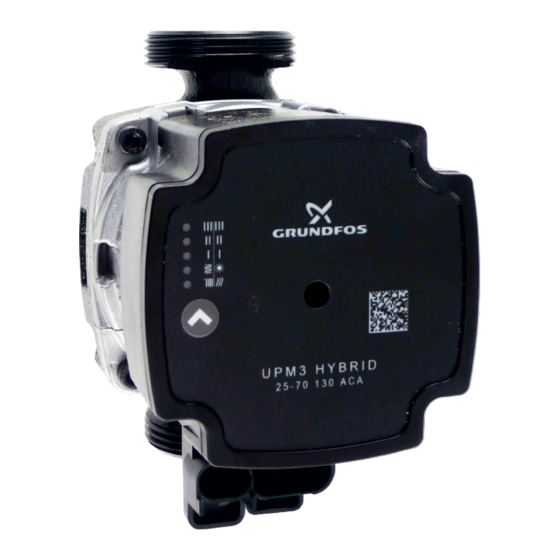
Grundfos UPM3 HYBRID 25-70 130 Installation And Operation Manual
Hide thumbs
Also See for UPM3 HYBRID 25-70 130:
- User manual ,
- Instructions manual (36 pages) ,
- Installation and operating instructions manual (24 pages)
Summary of Contents for Grundfos UPM3 HYBRID 25-70 130
- Page 1 Installation and Operation Manual Grundfos UPM3 HYBRID 25-70 130 mm Pump UPM3 HYBRID 25-70 130...
- Page 2 UPM3 HYBRID 25-70 130 mm Pump Design Wet-running circulation pump with G 6/4” M connection. Electrical Data Power supply 230 V, 50 Hz Power consumption (min./max.) 2/52W Current (min./max.) 0.04/0.52 A IP rating IP44 Max. speed 5766 rpm Weighted average power ≤...
- Page 3 Description of Pump Frofiles a) INTERNAL CONTROL - Proportional pressure • Head (pressure): reduced with growing system pressure drop and increased with sinking system pressure drop (typically e.g. opening / closing of thermostatic heads) • Pump operating point: moves up or down on the selected proportional pressure curve depending on the current system pressure drop.
- Page 4 e) EXTERNAL CONTROL - PWM A (heating) • The pump runs on a curve of constant speed depending on the current PWM value. • The speed slows down when the PWM value rises. If PWM equals 0, the pump runs at its max.
- Page 5 DISPLAY CONTROL MODE green LED FLASHING EXTERNAL PWM C PWM A GREEN LEDS FLASHING CONTROL PWM SIGNAL RECEPTION FREQUENCY Not flashing Internal 1 flash per second External 12 flashes per second External WARNING: LEDs may be turned by 90° or 180°, or mirrored, depending on the specific pump type. When switched on, the pump runs at factory settings or the last setting.
- Page 6 Prohibited pump positions Permissible pump positions Pump wiring N (blue) L (brown) PE (yellow-green) PWM GND (blue) PWM out (black) PWM in (brown) power supply (A) socket for power supply (A) and signal (B) terminals and signal transmission (B)
- Page 8 v1.0-03/2022 ©2022 We reserve the right to errors, changes and improvements without prior notice. REGULUS spol. s r.o. E-mail: sales@regulus.eu Web: www.regulus.eu...


Need help?
Do you have a question about the UPM3 HYBRID 25-70 130 and is the answer not in the manual?
Questions and answers