Table of Contents
Advertisement
Quick Links
Compact 28 SE
High efficiency combi boiler
Users Instructions
Installation &
Servicing
Instructions
THESE INSTRUCTIONS
TO BE RETAINED
BY USER
Vokèra is a licensed member of the Benchmark scheme
which aims to improve the standards of installation and
commissioning of domestic hot water systems in the UK.
Advertisement
Table of Contents

Related Manuals for VOKERA Compact 28 SE


Summary of Contents for VOKERA Compact 28 SE
- Page 1 Compact 28 SE High efficiency combi boiler Users Instructions Installation & Servicing Instructions THESE INSTRUCTIONS TO BE RETAINED BY USER Vokèra is a licensed member of the Benchmark scheme which aims to improve the standards of installation and commissioning of domestic hot water systems in the UK.
-
Page 2: Table Of Contents
Users instructions Things you should know Page Installation Page Gas appliances Delivery Electrical supply Contents Guarantee registration card Unpacking Appliance Log Book (UK only) Preparation for mounting the appliance How does it work? Fitting the flue Dimensions Connecting the gas & water Clearances required Electrical connections Frost protection system... -
Page 3: Users Instructions
USERS INSTRUCTIONS INTRODUCTION Dear Customer Your Vokèra Compact SE boiler has been designed to meet and exceed the very latest standards in gas central heating technology, and if cared for, will give years of reliable use and efficiency. Please therefore take some time to read these instructions carefully. Do’s and Don’t’s - Do ensure that the system pressure is periodically checked - Do ensure that the boiler should not be used by children or unassisted disabled people... -
Page 4: Checking The Co 2 And Adjusting The Gas Valve
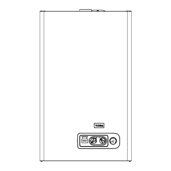
Fig. 1 TEMPERATURE RED LED SELECTOR PRESSURE GAUGE GREEN LED MODE SELECTOR SWITCH HEATING TEMPERATURE SELECTOR BOILER STATUS LED Green LED Boiler is working/responding to a heating/hot water request Red LED Boiler has identified a fault and has failed-safe. Refer to instructions on how to reset DHW TEMPERATURE SELECTOR Move the selector clockwise to increase the hot water outlet temperature, or counter-clockwise to reduce the temperature PRESSURE GAUGE... -
Page 5: Getting Started
2. GETTING STARTED 2.3 LIGHTING THE BOILER 2.1 BEFORE SWITCHING ON Ensure the gas and electrical supply to the boiler are turned on. Before switching the appliance on, please familiarise yourself with: Turn the mode selector switch to the ON position. When there - how to isolate the appliance from the gas, water, and elec- is a request for heating or hot water via the time clock or tricity supplies;... -
Page 6: What If
APPLIANCE STATUS LED AND FAULT CODES Alarm type Led RED Led GREEN Action Purge cycle mode active BLINKING BLINKING Alarm high limit thermostat Final BLINKING Reset appliance. Call engineer if fault re-occurs Alarm system water pressure Final Check/refill system pressure, reset, check. Call engineer if fault re-occurs Alarm safety shutdown and/or Final... -
Page 7: Installation And Servicing Instructions
The Compact 28 SE can also The Compact 28 SE is a standard-efficiency combination boiler be used with the Vokèra twin flue system. The Compact 28 SE with an output to CH & DHW of 28kW. This appliance – by is approved for use with C12-C32 type flue applications. -
Page 8: Principle Components
SECTION 1 - DESIGN PRINCIPLES AND OPERATING SEQUENCE 1.5 SAFETY DEVICES 1.1 PRINCIPLE COMPONENTS • A fully integrated electronic control board featuring electronic When the appliance is in use, safe operation is ensured by: • a water pressure switch that monitors system water pressure temperature control, anti-cycle control, pump over-run, self and will de-activate the pump, fan, and burner should the diagnostic fault indicator... -
Page 9: Technical Data
SECTION 2 - TECHNICAL DATA 2.1 Central Heating Compact 28 SE Heat input (kW) 30.20 Maximum heat output (kW) 60/80°C 28.24 Minimum working pressure 0.25-0.45 bar Maximum working pressure 3 bar Minimum flow rate 350 l/h 2.2 Domestic Hot Water... -
Page 10: Pump Duty
Below an opening or window on a pitched roof 2000 mm From a vertical terminal to an adjacent opening (window, air-brick, etc.) (call Vokera technical for advice) From a vertical terminal to an adjacent vertical terminal 300 mm (only if both terminals are the same hight) -
Page 11: General Requirements (Uk)
SECTION 3 - GENERAL REQUIREMENTS (UK) This appliance must be installed by a competent person in people have access (including balconies or flat roofs) the accordance with the Gas Safety (Installation & Use) terminal must be protected by a guard of durable material. Regulations. -
Page 12: Electrical Supply
with an approved non-return valve and stopcock for isolation 3.11 SHOWERS purposes. The feed pipe should be connected to the return If the appliance is intended for use with a shower, the shower pipe as close to the boiler as possible. must be thermostatically controlled and be suitable for use 3.6.8 FREQUENT FILLING with a combination boiler. -
Page 13: Air Supply
3A.7 ELECTRICAL SUPPLY terminal must be protected by a guard of durable material. The guard must be fitted centrally over the terminal. Refer to I.S. 813, The appliance is supplied for operation on 230V @ 50Hz when the terminal is 0.5 metres (or less) below plastic guttering electrical supply;... -
Page 14: Contents
4.5.2 CONCENTRIC HORIZONTAL FLUE (For concentric vertical flue, see 4.5.2). (For twin flue applications, see 4.5.3). The appliance can be used with either the Vokèra 60/100mm concentric Uni-flue system or the optional Vokera twin flue system. Total flue length 60-100 Restrictor required Up to 0.85 metre... - Page 15 These instructions relate only to the Vokèra 60/100mm concentric flue system. For specific details on the installation of the Vokera twin flue system please refer to the instructions supplied. The vertical flue terminal can be connected directly to the appliance flue outlet. Alternatively, an extension or bend...
- Page 16 to the maximum equivalent flue length) between the boiler and vertical flue assembly (see fig. 14). Ensure that any horizontal sections of the flue system have a minimum 1º; maximum 3º fall back to the boiler (1º = 17mm per 1000mm).
-
Page 17: Connecting The Gas & Water
NOTE • Before cutting twin flue pipes ensure allowances have been made for connection onto the previous piece and onto the concentric to twin converter. The last twin flue pipes must be pushed 50mm onto the male spigots of the concentric to twin converter. -
Page 18: Electrical Connections
refer to the wiring diagrams in section 8 for more detailed Cold water inlet information. Hot water stopcock/filling outlet valve 4.7.3 CONNECTING THE MAINS (230V) INPUT Unhook and remove the terminal block cover (230V). Pass the cock cable through the cable anchorage point. Connect the supply C/H flow cable wires (LIVE, NEUTRAL, &... -
Page 19: Gas Supply Installation
SECTION 5 - COMMISSIONING type, then it becomes necessary to carry out a combustion 5.1 GAS SUPPLY INSTALLATION analysis/check to ensure that correct combustion is occurring. Inspect the entire installation including the gas meter, test for If there are no means to gas rate the appliance and/or carry out tightness and purge. -
Page 20: Regulating The Central Heating System
It is important that the Benchmark checklist is correctly completed and handed to the user. Failure to install and com- us using the envelope supplied • online at: vokera.co.uk mission the appliance to the manufacturers instructions may • for UK residents by calling: 0870 607 0281 invalidate the warranty. -
Page 21: Pump Assembly
6.5 PUMP ASSEMBLY (fig. 21) Carry out component removal procedure as described in 6.4. Disconnect and remove the pump outlet pipe (A) from the pump assembly/combustion chamber connection. Remove the expansion pipe locking pin from the top of the pump assembly and withdraw the flexible pipe. Locate and remove the pressure gauge securing pin and disconnect the pressure gauge from the pump assembly. -
Page 22: Gas Valve
6.11 GAS VALVE (fig. 24) Carry out component removal procedure as described in 6.4. The gas valve must be changed as complete unit. Disconnect the electrical plug and leads from the gas valve, slacken and unscrew gas valve inlet and outlet pipes connections. Please note, the sealing washers (Q) must be discarded and replaced with new sealing washers. -
Page 23: Main Heat Exchanger
6.15 EXPANSION VESSEL REMOVAL (fig. 28) Carry out component removal procedure as described in 6.4. Disconnect the flexible expansion pipe from the vessel (fig. 28). Locate and remove the screws that secure the vessel (1). The expansion vessel can now be removed. Replace in the reverse order. -
Page 24: Checks, Adjustments And Fault Finding
SECTION 7 - CHECKS, ADJUSTMENTS AND FAULT FINDING 7.1 CHECKING APPLIANCE OPERATION 7.2.4 HOT WATER MODE Opening a hot water outlet and enabling a flow rate of 2 litres When carrying out any repairs or servicing to the appliance, the or more, causes the domestic water flow switch to activate. -
Page 25: Adjusting The Valve
- insert the jumper JP2 mA for G20 and 165 mA for LPG). - turn the domestic hot water temperature adjustment knob C - carefully prise out the protection cap of the adjustment until it reaches the heating maximum value as indicated in screws, using a screwdriver the multigas table - with a 10mm spanner, use the adjustment nut of the maximum... -
Page 26: Combustion Analysis Test
7.4 COMBUSTION ANALYSIS TEST Fixed green if there is flame, the boiler works regularly. To carry out the combustion analysis, proceed as follows: - open the hot water tap to its maximum output Red led - set the mode selector to summer and the domestic hot water The red led indicates a boiler lockout due to the following temperature selector to the maximum value faults:... -
Page 27: Fault Finding
7.7.5 RESISTANCE TO EARTH CHECK COMPONENT VALUES & Isolate the appliance from the electrical supply, and using a CHARACTERISTICS suitable multi-meter carry out a resistance test. Connect test leads between the Live & Earth connections at the appliance COMPONENT VALUE terminal strip. -
Page 28: Wiring Diagrams
SECTION 8 - WIRING DIAGRAMS 8.1 EXTERNAL WIRING MECHANICAL CLOCK - To allow basic operation of the boiler via the mode selector RADIO FREQUENCY RECEIVER switch a link must be fitted across the (‘CN5’) terminals on the PCB. If external controls are to be added to the system, they must be connected to the appliance as shown in the following diagrams. - Page 29 FUNCTIONAL DIAGRAM Fig. 41 NOTE: L-N-E connection is advisable...
-
Page 30: Exploded Diagrams
SECTION 9 - EXPLODED DIAGRAMS Table 1 POS. DESCRIPTION 28 SE Frame assembly 20020300 Quick primer pressure gauge 20005580 Cover 20005574 Printed circuit board MP08 20005569 Led light guide 20013352 Control panel 20035608 Knob 20013055 Case Assembly 20035613 Fuse R3478 Clip R5128 Ignition transformer... -
Page 31: Table 2
Table 2 POS. DESCRIPTION 28 SE Connection R10022658 By-pass valve R2047 Safety valve R2907 Fitting/union R10022499 Flow governor R9430 Pipe R10023950 Dhw actuator R10022349 Heating cock R1789 Connection R1790 Water supply stop cock R7099 Pipe 20013353 Cock 20000533 Pipe 20035609 Washer R5026 Washer... -
Page 32: Table 3
Table 3 POS. DESCRIPTION 28 SE Expansion vessel R2204 Pipe R10023603 Pump 20002906 Air vent bottle 20035019 Pipe R10023948 Heat exchanger R10023946 Pipe R10023947 Washer R2226 Washer R5026 High limit R2258 Clip R2223 Clip R2165 Washer R10022726 NTC sensor R10027352... -
Page 33: Table 4
Table 4 POS. DESCRIPTION 28 SE Air box bottom R10023904 Main burner injector manifold R10023902 Burner R10023901 Spark / ignition electrode R10025985 Gas pipe R10023996 Gas valve 20035533 Gas valve solenoid R10020838 3/4" gas cock R10020897 Cover assembly R10023928 Hole cover 20005586 Washer R5023... -
Page 34: Table 5
Table 5 POS. DESCRIPTION 28 SE Back insulatin panel R10023909 Combustion chamber insulation panel R2231 Combustion chamber insulation panel R10023910 R10023907 Pressure tube R10024191 Fan connection R10021972 Fumes testing connection pipe R10021973 Flue flange Ø 43 20020311 Flue flange Ø 45 20020309 Flue flange Ø... -
Page 35: Related Documents
SECTION 10 - LPG INSTRUCTIONS 10.1 RELATED DOCUMENTS BS 5440 PARTS 1 & 2 FLUES & VENTILATION REQUIREMENTS BS 5449 PART 1 FORCED CIRCULATION OF HOT WATER SYSTEMS BS 5482 PART 1 DOMESTIC BUTANE & PROPANE GAS BURNERS IN PERMAMENT DWELLINGS BS 5546 INSTALLATION OF GAS HOT WATER SUPPLIES FOR DOMESTIC... - Page 36 GAS BOILER SYSTEM COMMISSIONING CHECKLIST This Commissioning Checklist is to be completed in full by the competent person who commissioned the boiler as a means of demonstrating compliance with the appropriate Building Regulations and then handed to the customer to keep for future reference. Failure to install and commission this equipment to the manufacturer’s instructions may invalidate the warranty but does not affect statutory rights.
-
Page 37: Benchmark
SERVICE RECORD It is recommended that your heating system is serviced regularly and that the appropriate Service Record is completed. Service Provider Before completing the appropriate Service Record below, please ensure you have carried out the service as described in the manufacturer’s instructions. - Page 40 Registered address: Vokèra Ltd Borderlake House Unit 7 Riverside Industrial Estate London Colney Herts AL2 1HG enquiries@vokera.co.uk www.vokera.co.uk www.vokera.ie Sales, General Enquires T 0844 391 0999 F 0844 391 0998 Vokèra Ireland West Court, Callan Co Kilkenny T 056 7755057 F 056 7755060 Vokèra Limited reserve the right to change...
Need help?
Do you have a question about the Compact 28 SE and is the answer not in the manual?
Questions and answers