Table of Contents

Related Manuals for Toro 72098


Summary of Contents for Toro 72098
- Page 1 Form No. 3445-188 Rev C Z Master ® Professional 7500-D Series Riding Mower With 96in TURBO FORCE ® Rear Discharge Mower Model No. 72098—Serial No. 400000000 and Up *3445-188* Register at www.Toro.com. Original Instructions (EN)
- Page 2 Protection Agency (EPA) and the California Emission Control Regulation of emission systems, maintenance, and warranty. Replacements may be ordered through the engine manufacturer. © 2023—The Toro® Company Contact us at www.Toro.com. 8111 Lyndale Avenue South Printed in the USA Bloomington, MN 55420...
- Page 3 Authorized Service moderate injury. Dealer or Toro Customer Service and have the model and serial numbers of your product ready. Figure 1 identifies the location of the model and serial numbers on the product.
-
Page 4: Table Of Contents
Contents Draining the Fuel Filter/Water Separator ... 42 Replacing the Water Separator ......42 Checking the Fuel Lines and Safety ............... 5 Connections..........42 General Safety ........... 5 Electrical System Maintenance ......43 Slope Indicator ........... 6 Electrical System Safety ........43 Safety and Instructional Decals ...... -
Page 5: Safety
Safety This machine has been designed in accordance with ANSI standard B71.4-2017. General Safety This product is capable of amputating hands and feet and of throwing objects. Always follow all safety instructions to avoid serious personal injury or death. • Read and understand the contents of this Operator’s Manual before starting the engine. -
Page 6: Slope Indicator
Slope Indicator g011841 Figure 3 You may copy this page for personal use. 1. The maximum slope you can operate the machine on is 15 degrees. Use the slope chart to determine the degree of slope of hills before operating. Do not operate this machine on a slope greater than 15 degrees. Fold along the appropriate line to match the recommended slope. -
Page 7: Safety And Instructional Decals
Safety and Instructional Decals Safety decals and instructions are easily visible to the operator and are located near any area of potential danger. Replace any decal that is damaged or missing. decalbatterysymbols Battery Symbols Some or all of these symbols are on your battery. 1. - Page 8 decal112-9028 112-9028 1. Warning—stay away from moving parts; keep all guards and shields in place. decal116-5988 116-5988 1. Parking brake—engaged 2. Parking brake—disengaged decal107-3069 107-3069 1. Warning–there is no rollover protection when the roll bar is down. 2. To avoid injury or death from a rollover accident, keep the roll bar in the fully raised and locked position and wear the seat belt.
- Page 9 decal117-3276 117-3276 1. Engine coolant under 3. Warning—do not touch the pressure hot surface. 2. Explosion hazard—read 4. Warning—read the the Operator's Manual. Operator's Manual. decal126-8383 126-8383 Note: This machine complies with the industry standard stability test in the static lateral and longitudinal tests with the maximum recommended slope indicated on the decal.
- Page 10 decal126-9127 126-9127 1. Belt routing decal126-8760 126-8760 For Models with 244 cm (96-inch) Decks 1. Height of cut 2. Range adjustment decal126-9351 126-9351 1. Chassis (15 A) 3. Main (25 A) 2. Accessory (15 A) 4. Power point (15 A) decal126-9947 126-9947 1.
- Page 11 decal135-0328 135-0328 1. Torque the wheel lug nuts 2. Read and understand to 129 N∙m (95 ft-lb). the Operator's Manual before performing any maintenance; check the torque after the first 100 hours, then every 500 hours, thereafter. decal135-0398 135-0398 1. Engine—Off 4.
- Page 12 135-2837 1. Read the Operator’s Manual for more information; Use red Toro wet-clutch transmission fluid; do not use green hydraulic fluid. decal135-0670 135-0670 For Models with 244 cm (96-inch) Decks 2. Warning—lock the 1.
-
Page 13: Product Overview
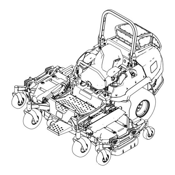
Product Overview g350919 Figure 4 1. Center deck height-of-cut 5. Motion-control lever 9. Audible alarm 13. Wing deck caster wheel 2. Wing deck height-of-cut pin 6. Display monitor 10. Power point 14. Center deck 3. Wing deck 7. Roll bar 11. -
Page 14: Controls
Controls Horizon Display Monitor Refer to the Software Guide for detailed information Become familiar with all the controls before you start explaining the operator interface that allows you to the engine and operate the machine. access information, reset counters, modify system settings, and troubleshoot the equipment. - Page 15 Blade-Control Switch (Power Alarm Takeoff) If an error occurs, an error message displays, the LED turns red, and the alarm sounds audibly as follows: The blade-control switch (PTO) engages and • A fast chirp sound indicates critical errors. disengages power to the mower blades (Figure •...
-
Page 16: Specifications
To ensure optimum performance and continued safety operator’s position. Allow the machine to cool certification of the machine, use only genuine Toro before servicing, adjusting, fueling, cleaning, or replacement parts and accessories. Replacement storing it. -
Page 17: Adding Fuel
Fuel Safety Adding Fuel • Fuel is extremely flammable and highly explosive. A fire or explosion from fuel can burn you and Recommended Fuel others and can damage property. The engine runs on clean, fresh diesel fuel with – To prevent a static charge from igniting the fuel, a minimum cetane rating of 40. -
Page 18: Performing Daily Maintenance
Using the Rollover Fill the fuel tank to the bottom of the filler neck (Figure Protection System (ROPS) Note: Do not fill the fuel tank completely full. The empty space in the tank allows the fuel to expand. WARNING To avoid injury or death from rollover, keep the roll bar in the fully raised, locked position and use the seat belt. -
Page 19: Using The Safety-Interlock System
Using the Safety-Interlock System WARNING If the safety-interlock switches are disconnected or damaged, the machine could operate unexpectedly, causing personal injury. • Do not tamper with the interlock switches. • Check the operation of the interlock switches daily and replace any damaged switches before operating the machine. -
Page 20: Positioning The Seat
Unlatching the Seat operate as described below, have an Authorized Service Dealer repair the safety system immediately. To unlatch the seat, push the seat latch forward Sit on the seat, engage the parking brake, and (Figure 12). move the blade-control switch (PTO) to the O position. -
Page 21: During Operation
Use your full attention while operating the • Use only accessories and attachments approved machine. Do not engage in any activity that by Toro. causes distractions; otherwise, injury or property • damage may occur. This machine produces sound levels in excess of 85 dBA at the operator’s ear and can cause... - Page 22 In the event of a rollover, take the machine to an while operating on slopes. Raising the deck while Authorized Service Dealer to inspect the ROPS. operating on slopes can cause the machine to • Use only Toro approved accessories and become unstable. attachments for the ROPS. Slope Safety •...
-
Page 23: Operating The Parking Brake
Disengaging the Parking Brake g221745 g227610 Figure 15 Figure 17 1. Safe Zone—use the 4. W = Width of the machine machine here on slopes less than 15° or flat areas. 2. Danger Zone—use a 5. Keep a safe distance walk-behind mower and/or (twice the width of the a hand trimmer on slopes... -
Page 24: Lowering The Wing Decks
Lowering the Wing Decks Operating the Mower Blade-Control Switch (PTO) Important: You must unfold the wing decks before you can engage the PTO. The blade-control switch (PTO) starts and stops the Remove the clevis pin and hairpin cotter that mower blades and any powered attachments. secures each wing in the upright position and place them in the storage position (Figure... -
Page 25: Starting The Engine
Starting the Engine Shutting Off the Engine Important: Do not engage the starter for more CAUTION than 5 seconds at a time. If the engine fails to start, wait 15 seconds between attempts. Failure Children or bystanders may be injured if they to follow these instructions can burn out the move or attempt to operate the machine while starter motor. -
Page 26: Raising And Locking The Wing Decks
Raising and Locking the Using the Motion-Control Wing Decks Levers Ensure that all persons are clear of the deck wings. Press and hold the bottom of the deck-lift switch; the center deck lowers first, then the outer wings. Park the machine on a level surface, disengage the blade-control switch, and engage the parking brake. -
Page 27: Driving The Machine
Driving the Machine The drive wheels turn independently, powered by hydraulic motors on each axle. You can turn 1 side in reverse while you turn the other forward, causing the machine to spin rather than turn. This greatly improves the machine maneuverability but may require some time for you to adapt to how it moves. -
Page 28: Adjusting The Height Of Cut
Adjusting the Height of Cut Lock the cam lock. Repeat for the other wing deck. The cutting height of the mower deck can be adjusted from 2.54 cm to 14 cm (1 to 5-1/2 inches) in 6.4 mm If you desire additional height-of-cut range, (1/4 inch) increments. -
Page 29: Adjusting The Anti-Scalp Rollers
Adjusting the Anti-Scalp Rollers For maximum deck flotation, install the rollers 1 hole position lower. Rollers should maintain a 6 mm (1/4 inch) clearance to the ground. Do not adjust the rollers to support the deck. Park the machine on a level surface. Disengage the blade-control switch (PTO), move the motion-control levers to the N EUTRAL... -
Page 30: Adjusting The Skids
Adjusting the Skids Operating Tips Mount the skids in the lower position when operating Using the Fast Throttle Setting at heights of cut greater than 51 mm (2 inches) and in a higher position when operating at heights of cut For best mowing and maximum air circulation, operate lower than 51 mm (2 inches). -
Page 31: After Operation
Check the mower blades after each use for sharpness, and for any wear or damage. File down any nicks and sharpen the blades as necessary. If a blade is damaged or worn, replace it immediately with a genuine Toro replacement blade. -
Page 32: Using The Drive-Wheel Release Valves
Using the Drive-Wheel Selecting a Trailer Release Valves WARNING Use the drive-wheel release valves to release the Loading a machine onto a trailer or truck hydrostatic drive system, which allows you to push the increases the possibility of tip-over and could machine without the running the engine. - Page 33 If using a trailer, connect it to the towing vehicle and connect the safety chains. If applicable, connect the trailer brakes and lights. Lower the ramp, ensuring that the angle between the ramp and the ground does not exceed 15 degrees (Figure 34).
-
Page 34: Maintenance
Keep your hands and feet away from moving • To ensure optimum performance, use only parts or hot surfaces. If possible, do not make genuine Toro replacement parts and accessories. adjustments with the engine running. Replacement parts and accessories made by •... -
Page 35: Lubrication
• Grease the caster pivots (more often in dirty or dusty conditions). • Change the engine oil and filter if not using Toro Premium Engine Oil, but any oil meeting API classification CJ-4 or higher or as stated in Engine-Oil Specifications. -
Page 36: Lubricating The Drive U-Joints And Splined Slip Joint
Lubricating the Drive Lubrication Chart U-Joints and Splined Slip Fitting Pumps Number of Service Locations Places Interval Joint Yearly Caster-wheel Service Interval: Every 50 hours—Grease the drive bearings U-joints and splined slip joint. 4. Caster Every 400 pivots hours or Note: For easier access to the drive U-joints and yearly... -
Page 37: Lubricating The Mower Deck-Lift Pivots
Lubricating the Mower Deck-Lift Pivots Service Interval: Every 100 hours Use light oil or spray lubricant to lubricate the deck-lift pivots. g017050 Figure 38 Greasing the Caster Pivots Service Interval: Every 200 hours/Yearly (whichever comes first) (more often in dirty or dusty conditions). -
Page 38: Greasing The Caster-Wheel Hubs
Greasing the Caster-Wheel With the open end of the wheel facing up, fill the area inside the wheel around the axle full of Hubs general-purpose grease. Insert the second bearing and new seal into the Service Interval: Yearly wheel. Park the machine on a level surface, disengage Apply a thread-locking compound to the second the blade-control switch, and engage the parking spacer nut, and thread it onto the axle with the... -
Page 39: Engine Maintenance
Engine Maintenance Servicing the Air Cleaner Note: If the foam gasket in the cover is damaged, replace it. Engine Safety Important: Avoid using high-pressure air, which • Keep your hands, feet, face, clothing, and other could force dirt through the filter into the intake body parts away from the muffler and other hot tract. -
Page 40: Servicing The Engine Oil
After the first 200 hours—Change the engine oil and filter. Every 200 hours—Change the engine oil and filter if not using Toro Premium Engine Oil, but any oil meeting API classification CJ-4 or higher or as stated in Engine-Oil Specifications. -
Page 41: Inspecting The Engine-Valve Clearance
Changing the Engine Oil and Filter If possible, run the engine just before changing the oil because warm oil flows better and carries more contaminants than cold oil. Park the machine on a level surface, disengage the blade-control switch (PTO), and engage the parking brake. -
Page 42: Fuel System Maintenance
Replacing the Water Fuel System Separator Maintenance Service Interval: Every 400 hours—Replace the WARNING fuel-filter canister for the water separator (more often in dirty and Fuel-system components are under high dusty conditions). pressure. The use of improper components can result in system failure, fuel leakage, and possible explosion. -
Page 43: Electrical System Maintenance
Electrical System Voltage Percent Maximum Charging Reading Charge Charger Interval Maintenance Settings 12.6 V or 100% 16 V/7 A No charging greater required Electrical System Safety 12.4 V to 12.6 75% to 100% 16 V/7 A 30 minutes • Disconnect the battery before repairing the 12.2 V to 12.4 50% to 75% 16 V/7 A... - Page 44 Charging the Battery Jump-Starting the Machine Check the weak battery for terminal corrosion WARNING (white, green, or blue “snow”). Charging the battery produces gasses that You must clean it off prior to jump-starting. Clean and tighten connections as necessary. can explode. Never smoke near the battery and keep sparks CAUTION and flames away from battery.
-
Page 45: Servicing The Fuses
Servicing the Fuses Connect the positive (+) cable to the positive (+) terminal of the discharged battery that is wired to the starter or solenoid (Figure 48). The electrical system is protected by fuses. It requires no maintenance, however, if a fuse blows check component/circuit for malfunction or short. -
Page 46: Drive System Maintenance
Drive System Align the levers in the front-to-rear position by bringing the levers together to the N EUTRAL Maintenance position, and slide them until they are aligned, then tighten the bolts (Figure 51). Checking the Seat Belt Service Interval: Before each use or daily Inspect the seat belt for wear, cuts, and proper operation of the retractor and buckle. -
Page 47: Checking The Tire Pressure
Checking the Tire Pressure Adjusting the Frame Caster-Pivot Bearing Service Interval: Every 50 hours/Monthly (whichever comes first) Service Interval: Every 200 hours/Yearly (whichever Rear tire air pressure specification: 124 kPa (18 comes first) psi). Park the machine on a level surface, disengage Note: the blade-control switch, and engage the parking The caster tires are semi-pneumatic tires and... -
Page 48: Cooling System Maintenance
Cooling System Maintenance Cooling System Safety • Swallowing engine coolant can cause poisoning; keep out of reach from children and pets. • Discharge of hot, pressurized coolant or touching a hot radiator and surrounding parts can cause severe burns. – Always allow the engine to cool at least 15 minutes before removing the radiator cap. -
Page 49: Changing The Engine Coolant
Note: If debris remains, repeat until clean. Operate engine until the engine thermostat opens and the coolant is circulating through the Lower the hood. radiator core. Start the engine to ensure that the fan functions As air purges from the engine block and the properly. -
Page 50: Brake Maintenance
Brake Maintenance Adjusting the Parking Brake Service Interval: After the first 100 hours Every 400 hours Check to ensure that parking brake is adjusted properly. Follow this procedure also whenever you have removed or replaced a brake component. Park the machine on a level surface, disengage the blade-control switch, and engage the parking brake. -
Page 51: Belt Maintenance
Belt Maintenance Repeat steps through until a visible gap is achieved and the wheel hub rotates freely. Repeat this procedure for the other side. Inspecting the Belts Note: The brake should fully disengage when the brake is in the released position. Service Interval: Every 50 hours Rotate the drive wheel release handle to Replace the belt if it is worn. - Page 52 g243945 Figure 59 g243947 Figure 60 1. Square hole in the idler 3. Spring 1. Spring-loaded idler pulley 3. Spring arm for the ratchet 2. Wing deck mower belt 2. Square hole in the idler 4. Center deck mower belt arm for the ratchet Install the new belt around the mower deck Install the new belt around the mower deck...
-
Page 53: Checking The Alternator-Belt Tension
Checking the Controls System Alternator-Belt Tension Maintenance Service Interval: Every 100 hours Adjusting the Apply 44 N (10 lb) of force to the alternator belt, midway between the pulleys. Control-Handle Position If the deflection is not 10 mm (3/8 inch), loosen the alternator mounting bolts (Figure 61). -
Page 54: Adjusting The Motion-Control Linkage
Raise the rear of the machine up and support it with jack stands (or equivalent support) just high enough to allow the drive wheels to turn freely. Remove the electrical connection from the seat safety switch, located under the bottom cushion of the seat. -
Page 55: Adjusting The Motion-Control Damper
Catalog or contact an authorized Toro distributor for part numbers.) g008620 Figure 65 Alternate fluids: If the Toro fluid is not available, Right Motion Control Shown Mobil® 424 hydraulic fluid may be used. Note: Toro does not assume responsibility for 1. - Page 56 Remove the hydraulic-tank cap (Figure 66). and filter if using Mobil® 424 hydraulic fluid. Every 800 hours—Change the hydraulic fluid and filter if using Toro Premium Transmission/Hydraulic Tractor Fluid. Disengage the PTO, move the motion-control levers to the N position, and...
-
Page 57: Mower Deck Maintenance
On multi-bladed machines, take care as rotating Fill each wheel motor with approximately one blade can cause other blades to rotate. 1.4 L (1.5 US qt) of Toro Premium • Transmission/Hydraulic Tractor Fluid. Replace worn or damaged blades and bolts in sets to preserve balance. - Page 58 Note: If this dimension exceeds 3 mm (1/8 inch), the blade is bent and must be replaced. DANGER A blade that is bent or damaged could break apart and could seriously injure or kill you or bystanders. • Always replace bent or damaged g006530 blade with a new blade.
-
Page 59: Leveling The Mower Deck
Sharpening the Blades Install the bushing/blade assembly into the spindle shaft (Figure 76). Use a file to sharpen the cutting edge at both ends of the blade (Figure 73). Note: Maintain the original angle. Note: The blade retains its balance if the same amount of material is removed from both cutting edges. - Page 60 Hold the switch down until both wings are completely folded. Position the mower to the 102 mm (4 inches) height-of-cut position. Unlock the left and right wing deck cam locks (Figure 77). Remove and retain the wing deck height-of-cut lanyard (Figure 77).
- Page 61 height of cut with the desired rake, you can utilize the single-point adjustment to gain more adjustment. To adjust the single-point system, first loosen the front and rear height-of-cut plate mounting bolts (Figure Fine-tune the rear adjusters as required. You can adjust the single-point adjustment to gain more adjustment.
-
Page 62: Checking The Deck Drive Gearbox-Oil Level
Checking the Deck Drive Gearbox-Oil Level Service Interval: Every 50 hours Use SAE 75W-90 synthetic gear lube. Park the machine on a level surface and engage the parking brake. Lower the mower deck to the 25 mm (1 inch) height of cut. Disengage the blade-control switch, shut off the engine, remove the key, and wait for all moving parts to stop before leaving the operating... -
Page 63: Changing The Deck Drive Gearbox Oil
LOCK Every 400 hours position, and engage the parking brake. If the oil becomes contaminated, contact your Toro Shut off the engine, remove the key, and wait Distributor because the system must be flushed. for all moving parts to stop before leaving the Contaminated oil looks milky or black when compared operating position. - Page 64 Note: Do not pull the wing decks into the operating position in order to remove the cylinder pins. g351363 Figure 86 1. Upper pivot point bushing 3. Deck pin assembly 2. Lower pivot point bolt 4. Bushing Apply a thin bead of Loctite ®...
-
Page 65: Adjusting The Wing Deck Caster-Pivot Bearings
Adjusting the Wing Deck Caster-Pivot Bearings Service Interval: Every 200 hours/Yearly (whichever comes first) Park the machine on a level surface, disengage the blade-control switch, and engage the parking brake. Shut off the engine, remove the key, and wait for all moving parts to stop before leaving the operating position. -
Page 66: Cleaning
Cleaning Cleaning the Engine and Exhaust System Area Service Interval: Before each use or daily—Clean the engine and exhaust system area. Important: Do not use water to clean the engine. Use low-pressure compressed air. See the engine owner's manual. Park the machine on a level surface, disengage the blade-control switch (PTO), and engage the parking brake. -
Page 67: Storage
Storage Check the condition of the blades; refer to Servicing the Cutting Blades (page 57). Prepare the machine for storage when non-use Storage Safety occurs over 30 days. Prepare the machine for storage as follows: • Shut off the engine, remove the key, and wait for all moving parts to stop before you leave the Add a petroleum-based operator’s position. -
Page 68: Troubleshooting
Troubleshooting Problem Possible Cause Corrective Action The starter does not crank. 1. The blade-control switch is engaged. 1. Disengage the blade-control switch. 2. The parking brake is disengaged. 2. Engage the parking brake. 3. The motion-control levers are not in 3. - Page 69 Problem Possible Cause Corrective Action The machine does not drive. 1. The bypass valves are not closed tight. 1. Tighten the bypass valves. 2. The pump belt is worn, loose, or 2. Change the belt. broken. 3. The pump belt is off a pulley. 3.
-
Page 70: Schematics
Schematics g241314 Electrical Schematic—Machine with Horizon Display Monitor (Rev. A) - Page 71 g239212 Hydraulic Schematic (Rev. A)
- Page 72 g232910 Electrical Schematic—Yanmar Engine 3TNV88C (Rev. A)
- Page 73 Notes:...
- Page 74 Notes:...
- Page 75 Notes:...
- Page 76 While the exposure from Toro products may be negligible or well within the “no significant risk” range, out of an abundance of caution, Toro has elected to provide the Prop 65 warnings. Moreover, if Toro does not provide these...