Toro Z Master Professional 7500-D Series Operator's Manual
Hide thumbs
Also See for Z Master Professional 7500-D Series:
- Operator's manual (300 pages) ,
- Service manual (179 pages) ,
- Setup instructions (12 pages)
Table of Contents

Related Manuals for Toro Z Master Professional 7500-D Series


Summary of Contents for Toro Z Master Professional 7500-D Series
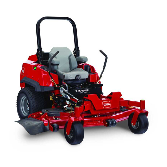
- Page 1 Form No. 3445-180 Rev A Z Master ® Professional 7500-D Series Riding Mower With 144in TURBO FORCE ® Rear Discharge Mower Model No. 72144—Serial No. 400000000 and Up *3445-180* Register at www.Toro.com. Original Instructions (EN)
- Page 2 Authorized Service requirements, the actual engine torque on this class Dealer or Toro Customer Service and have the model of mower will be significantly lower. Please refer to and serial numbers of your product ready.
- Page 3 The safety-alert symbol (Figure 2) appears both in this manual and on the machine to identify important safety messages that you must follow to avoid accidents. This symbol will appear with the word Danger, Warning, or Caution. • Danger indicates an imminently hazardous situation which, if not avoided, will result in death or serious injury.
-
Page 4: Table Of Contents
Contents Draining the Fuel Filter/Water Separator ... 48 Replacing the Water Separator ......49 Checking the Fuel Lines and Safety ............... 5 Connections..........49 General Safety ........... 5 Electrical System Maintenance ......50 Slope Indicator ........... 6 Electrical System Safety ........50 Safety and Instructional Decals ...... -
Page 5: Safety
Safety This machine has been designed in accordance with ANSI standard B71.4-2017. General Safety This product is capable of amputating hands and feet and of throwing objects. Always follow all safety instructions to avoid serious personal injury or death. • Read and understand the contents of this Operator’s Manual before starting the engine. -
Page 6: Slope Indicator
Slope Indicator g011841 Figure 3 You may copy this page for personal use. 1. The maximum slope you can operate the machine on is 15 degrees. Use the slope chart to determine the degree of slope of hills before operating. Do not operate this machine on a slope greater than 15 degrees. Fold along the appropriate line to match the recommended slope. -
Page 7: Safety And Instructional Decals
Safety and Instructional Decals Safety decals and instructions are easily visible to the operator and are located near any area of potential danger. Replace any decal that is damaged or missing. decalbatterysymbols Battery Symbols Some or all of these symbols are on your battery. 1. - Page 8 decal117-3276 117-3276 1. Engine coolant under 3. Warning—do not touch the pressure hot surface. 2. Explosion hazard—read 4. Warning—read the decal109-6036 the Operator's Manual. Operator's Manual. 109-6036 Rear Discharge Machines Only 1. Read the Operator’s Manual. 2. Remove the key and read the instructions before servicing or performing maintenance.
- Page 9 decal126-8383 126-8383 Note: This machine complies with the industry standard stability test in the static lateral and longitudinal tests with the maximum recommended slope indicated on the decal. Review the instructions for operating the machine on slopes in the Operator’s Manual as well as the conditions in which you would operate the machine to determine whether you can operate the machine in the conditions on that day and at that site.
- Page 10 135-2837 1. Read the Operator’s Manual for more information; Use red Toro wet-clutch transmission fluid; do not use green hydraulic fluid.
- Page 11 decal142-3903 142-3903 1. Front of the mower deck decal142-3953 142-3953 1. Machine speed 4. Neutral 2. Fast 5. Reverse 3. Slow 6. Parking brake—engaged decal142-3952 142-3952 1. Machine speed 4. Neutral 2. Fast 5. Reverse 3. Slow 6. Parking brake—engaged decal142-3956 142-3956 1.
- Page 12 decal142-6728 142-6728 1. Chassis (15 A) 4. Power port (15 A) 2. Accessory (15 A) 5. Fan, photo relay 3. Main (25 A) decal142-7835 142-7835 1. Read the instructions before servicing or performing 9. Check the air cleaner maintenance. 2. Time interval 10.
-
Page 13: Product Overview
Product Overview g362295 Figure 4 6. Audible alarm 11. Anti-scalp roller 1. Center deck height-of-cut pin 2. Wing deck height-of-cut pin 7. Fuel gauge 12. Center deck 3. Motion-control lever 8. Fuel-tank cap 13. Machine caster wheel 4. Display monitor 9. -
Page 14: Controls
Controls Horizon Display Monitor Refer to the Software Guide for detailed information Become familiar with all the controls before you start explaining the operator interface that allows you to the engine and operate the machine. access information, reset counters, modify system settings, and troubleshoot the equipment. - Page 15 Blade-Control Switch (Power • Solid green—indicates normal operating activity • Takeoff) Blinking red—indicates an active fault • Blinking green and orange— indicates that a The blade-control switch (PTO) engages and clutch reset is required disengages power to the mower blades (Figure Refer to the Software Guide for more information.
-
Page 16: Specifications
To ensure optimum performance and continued safety certification of the machine, use only genuine Toro replacement parts and accessories. Replacement g362882 parts and accessories made by other manufacturers Figure 7 could be dangerous, and such use could void the product warranty. -
Page 17: Before Operation
Fuel Safety Operation • Fuel is extremely flammable and highly explosive. A fire or explosion from fuel can burn you and Note: Determine the left and right sides of the others and can damage property. machine from the normal operating position. –... -
Page 18: Adding Fuel
Adding Fuel Fill the fuel tank to the bottom of the filler neck (Figure Note: Do not fill the fuel tank completely full. Recommended Fuel The empty space in the tank allows the fuel to expand. The engine runs on clean, fresh diesel fuel with a minimum cetane rating of 40. -
Page 19: Using The Rollover Protection System (Rops)
Using the Rollover Protection System (ROPS) WARNING To avoid injury or death from rollover, keep the roll bar in the fully raised, locked position and use the seat belt. Ensure that the seat is secured to the machine. WARNING There is no rollover protection when the roll g225804 Figure 10 bar is in the down position. -
Page 20: Adjusting The Mirrors
Adjusting the Mirrors While in the operating position, the mirrors should provide a wide-angle view to assist with blind spots. Adjust the left and right mirror to ensure that you have an optimal viewing angle. Using the Motion-Control Levers g004532 Figure 12 1. -
Page 21: Checking The Safety-Interlock System
Checking the Safety-Interlock System Service Interval: Before each use or daily WARNING If the safety-interlock switches are disconnected or damaged, the machine could operate unexpectedly, causing personal injury. • Do not tamper with the interlock switches. • Check the operation of the interlock switches daily and replace any damaged switches before operating the machine. - Page 22 Checking the Engine-Starting Circuit Chart Note: In the Checking the Engine-Starting Circuit Chart, the state of system item that is in bold text is being checked in each scenario. System Motion Control PTO (Blades) Operator Outcome Levers/Parking Brake Both levers moved in, or Disengaged Operator in the seat Starter must not crank...
- Page 23 Checking the Shutdown-Circuit Chart Note: The state of the system items in bold text are being checked in each scenario. System Engine Motion Control PTO (Blades) Operator Outcome Levers/Parking Brake Running idle (1/3 throttle Both levers moved Disengaged Raise off the Engine must begin in, or right or left shutdown within 1 second...
- Page 24 Running idle (1/3 throttle Both levers moved Engaged and Deck Operator in the PTO must begin or efficient mode) in, or right or left wings up seat shutdown within 1 lever moved in second; engine stays = Parking Brake running. Disengaged State of System...
-
Page 25: Positioning The Seat
Positioning the Seat Changing the Seat Suspension The seat moves forward and backward. Position the seat where you have the best control of the machine The seat is adjustable to provide a smooth and and are most comfortable. comfortable ride. Position the seat where you are To adjust, move the lever sideways to unlock the seat most comfortable. -
Page 26: During Operation
Use your full attention while operating the • Use only accessories and attachments approved machine. Do not engage in any activity that by Toro. causes distractions; otherwise, injury or property • damage may occur. This machine produces sound levels in excess of 85 dBA at the operator’s ear and can cause... - Page 27 In the event of a rollover, take the machine to an while operating on slopes. Raising the deck while Authorized Service Dealer to inspect the ROPS. operating on slopes can cause the machine to • Use only Toro approved accessories and become unstable. attachments for the ROPS. Slope Safety •...
-
Page 28: Lowering The Wing Decks
Lowering the Wing Decks Important: You must unfold the wing decks before you can engage the PTO. Remove the clevis pin and hairpin cotter that secures each wing in the upright position and place them in the storage position (Figure 18 Figure 19). -
Page 29: Operating The Mower Blade-Control Switch (Pto)
Operating the Mower Blade-Control Switch (PTO) The blade-control switch (PTO) starts and stops the mower blades and any powered attachments. Engaging the Blade-Control Switch (PTO) Note: Engaging the blade-control switch (PTO) with the throttle position at half or less causes excessive wear to the drive belts. -
Page 30: Starting The Engine
Starting the Engine Shutting Off the Engine Important: Do not engage the starter for more CAUTION than 5 seconds at a time. If the engine fails to start, wait 15 seconds between attempts. Failure Children or bystanders may be injured if they to follow these instructions can burn out the move or attempt to operate the machine while starter motor. -
Page 31: Raising And Locking The Wing Decks
Raising and Locking the Wing Decks Ensure that all persons are clear of the deck wings. Park the machine on a level surface, disengage the blade-control switch, and engage the parking brake. Press and hold the top of the deck-control switch;... -
Page 32: Driving The Machine
Driving the Machine The drive wheels turn independently, powered by hydraulic motors on each axle. You can turn 1 side in reverse while you turn the other forward, causing the machine to spin rather than turn. This greatly improves the machine maneuverability but may require some time for you to adapt to how it moves. -
Page 33: Adjusting The Height Of Cut
Adjusting the Height of Cut Lock the cam lock. Repeat for the other wing deck. The cutting height of the mower deck can be adjusted from 2.54 cm to 14 cm (1 to 5-1/2 inches) in 6.4 mm If you desire additional height-of-cut range, (1/4 inch) increments. -
Page 34: Adjusting The Anti-Scalp Rollers
Adjusting the Anti-Scalp Rollers For maximum deck flotation, install the rollers 1 hole position lower. Rollers should maintain a 6 mm (1/4 inch) clearance to the ground. Do not adjust the rollers to support the deck. Park the machine on a level surface. Disengage the blade-control switch (PTO), move the motion-control levers to the N EUTRAL... -
Page 35: Operating With The Overheat Sensor
Cutting more than that is not recommended unless damaged or worn, replace it immediately with a grass is sparse, or it is late fall when grass grows genuine Toro replacement blade. more slowly. Alternating the Mowing Direction Alternate the mowing direction to keep the grass standing straight. -
Page 36: After Operation
Using the Drive Train Brake After Operation Release After Operation Safety The drive train brake releases are located on each of the wheel-motor gearboxes. General Safety Releasing the drive train brake allows you to push the machine without the engine running. •... -
Page 37: Using The Wing Deck Fold Release Valve
Using the Wing Deck Fold Using lifting equipment with at least a 227 kg (500 lb) lifting capacity, carefully pull 1 wing Release Valve deck outward, then upward to fold it. Secure the wing using the transport-lock pin. WARNING Repeat this procedure for the other wing deck. The wing decks are very heavy. -
Page 38: Transporting The Machine
Transporting the Machine Use a heavy-duty trailer or truck to transport the machine. Use a full-width ramp. Ensure that the trailer or truck has all the necessary brakes, lighting, and marking as required by law. Please carefully read all the safety instructions. Knowing this information could help you or bystanders avoid injury. - Page 39 If using a trailer, connect it to the towing vehicle and connect the safety chains. If applicable, connect the trailer brakes and lights. Lower the ramp, ensuring that the angle between the ramp and the ground does not exceed 15 degrees (Figure 35).
-
Page 40: Maintenance
• Check the alternator-belt tension. Every 100 hours • Change the engine oil and filter if not using Toro Premium Engine Oil, but any oil Every 200 hours meeting API classification CJ-4 or higher or as stated in Engine-Oil Specifications. - Page 41 • Grease the caster pivots (more often in dirty or dusty conditions). • Service the air cleaner (More frequently in extremely dusty or dirty conditions). • Change the engine oil and filter if using Toro Premium Engine Oil (API classification CK-4 or higher) more often in dirty and dusty conditions.
-
Page 42: Lubrication
Lubrication Greasing the Machine Service Interval: Every 400 hours/Yearly (whichever comes first)—Grease the deck-idler pivots. Yearly—Grease the deck drive PTO. Grease more frequently when operating conditions are extremely dusty or sandy. Grease Type: No. 2 lithium or molybdenum grease Park the machine on a level surface, disengage the blade-control switch, and engage the parking brake. -
Page 43: Lubricating The Drive U-Joints And Splined Slip Joint
Lubricating the Drive Greasing the Caster Pivots U-Joints and Splined Slip Service Interval: Every 400 hours/Yearly (whichever comes first) (more often in dirty or Joint dusty conditions). Yearly—Repack the caster-wheel bearings Service Interval: Every 50 hours—Grease the drive (more often in dirty or dusty conditions). U-joints and splined slip joint. -
Page 44: Greasing The Caster-Wheel Hubs
Greasing the Caster-Wheel With the open end of the wheel facing up, fill the area inside the wheel around the axle full of Hubs general-purpose grease. Insert the second bearing and new seal into the Service Interval: Yearly wheel. Park the machine on a level surface, disengage Apply a thread-locking compound to the second the blade-control switch, and engage the parking spacer nut, and thread it onto the axle with the... -
Page 45: Engine Maintenance
Engine Maintenance Servicing the Air Cleaner Note: If the foam gasket in the cover is damaged, replace it. Engine Safety Important: Avoid using high-pressure air, which • Keep your hands, feet, face, other body parts, could force dirt through the filter into the intake and clothing away from the muffler and other hot tract. -
Page 46: Servicing The Engine Oil
Crankcase capacity: 6.6 L (7 US qt) with the filter Preferred engine oil: Toro Premium Engine Oil If using an alternate oil, use high-quality, low-ash engine oil that meets or exceeds the following specifications: •... -
Page 47: Inspecting The Engine-Valve Clearance
Service Interval: After the first 200 hours—Change the engine oil and filter. Every 200 hours—Change the engine oil and filter if not using Toro Premium Engine Oil, but any oil meeting API classification CJ-4 or higher or as stated in Engine-Oil Specifications. -
Page 48: Fuel System Maintenance
Fuel System Maintenance WARNING Fuel-system components are under high pressure. The use of improper components can result in system failure, fuel leakage, and possible explosion. Use only approved fuel lines and fuel filters. Draining the Fuel Filter/Water Separator Service Interval: Every 50 hours—Drain the fuel filter/water separator. -
Page 49: Replacing The Water Separator
Replacing the Water Separator Service Interval: Every 400 hours—Replace the fuel-filter canister for the water separator (more often in dirty and dusty conditions). g233831 Figure 47 1. Filter locations Checking the Fuel Lines and Connections Service Interval: Every 400 hours Inspect the fuel lines for deterioration, damage, chaffing, or loose connections. -
Page 50: Electrical System Maintenance
Electrical System Voltage Percent Maximum Charging Reading Charge Charger Interval Maintenance Settings 12.6 V or 100% 16 V/7 A No charging greater required Electrical System Safety 12.4 V to 12.6 75% to 100% 16 V/7 A 30 minutes • Disconnect the cable from the negative terminal of 12.2 V to 12.4 50% to 75% 16 V/7 A... - Page 51 Charging the Battery Jump-Starting the Machine Check the weak battery for terminal corrosion WARNING (white, green, or blue “snow”). Charging the battery produces gasses that You must clean it off prior to jump-starting. Clean and tighten connections as necessary. can explode. Never smoke near the battery and keep sparks CAUTION and flames away from battery.
-
Page 52: Servicing The Fuses
Servicing the Fuses Connect the positive (+) cable to the positive (+) terminal of the discharged battery that is wired to the starter or solenoid (Figure 49). The electrical system is protected by fuses. It requires no maintenance, however, if a fuse blows check component/circuit for malfunction or short. -
Page 53: Drive System Maintenance
Drive System Align the levers in the front-to-rear position by bringing the levers together to the N EUTRAL Maintenance position, and slide them until they are aligned, then tighten the bolts (Figure 52). Checking the Seat Belt Service Interval: Before each use or daily Inspect the seat belt for wear, cuts, and proper operation of the retractor and buckle. -
Page 54: Checking The Tire Pressure
Checking the Tire Pressure Adjusting the Caster-Pivot Bearing Service Interval: Every 50 hours/Monthly (whichever comes first) Service Interval: Every 500 hours/Yearly (whichever Rear tire air pressure specification: 152 kPa (22 comes first) psi) Park the machine on a level surface, disengage Note: the blade-control switch, and engage the parking The caster tires are semi-pneumatic tires and... -
Page 55: Servicing The Gearbox
Checking the Gearbox-Oil Level Every 400 hours Service Interval: Every 50 hours If the oil becomes contaminated, contact your Toro Distributor because the system must be flushed. Use SAE 75W-90 synthetic gear lube. Contaminated oil looks milky or black when compared Park the machine on a level surface and engage to clean oil. -
Page 56: Checking The Drive Wheel Gearbox Oil
Checking the Drive Wheel Changing the Drive Wheel Gearbox Oil Gearbox Oil Service Interval: Every 400 hours Service Interval: After the first 50 hours Park the machine on a level surface, disengage Every 800 hours the blade-control switch, and engage the parking Park the machine on a level surface, disengage brake. -
Page 57: Cooling System Maintenance
Cooling System Maintenance Cooling System Safety • Swallowing engine coolant can cause poisoning; keep out of reach from children and pets. • Discharge of hot, pressurized coolant or touching a hot radiator and surrounding parts can cause severe burns. – Always allow the engine to cool at least 15 minutes before removing the radiator cap. -
Page 58: Changing The Engine Coolant
If the radiator is clean, proceed to step 8. Allow some room (approximately 12.7 mm (1/2 inch)) for expansion. Add 50/50 coolant mix to Cover the engine with a piece of cardboard or the overflow bottle on the left side of the engine a plastic sheet. -
Page 59: Belt Maintenance
Belt Maintenance Remove the belt from the mower deck pulleys (Figure 61). Inspecting the Belts Service Interval: Every 50 hours Check the belts whenever they squeal while rotating, the blades slip while cutting grass, or if the belts have frayed edges, burn marks, or cracks. If any of these conditions occur, replace the belts. -
Page 60: Checking The Alternator-Belt Tension
Checking the Alternator-Belt Tension Service Interval: Every 100 hours Apply 44 N (10 lb) of force to the alternator belt, midway between the pulleys. If the deflection is not 10 mm (3/8 inch), loosen the alternator mounting bolts (Figure 63). g243947 Figure 62 1. -
Page 61: Controls System Maintenance
Controls System Maintenance Adjusting the Control-Handle Position There are 2 height positions for the control levers—high and low. Remove the bolts to adjust the height for the operator. Park the machine on a level surface, disengage the blade-control switch (PTO), and engage the parking brake. -
Page 62: Adjusting The Motion-Control Damper
Note: Raise the rear of the machine up and support it The wheels should stop turning or slightly with jack stands (or equivalent support) just high creep in reverse. enough to allow the drive wheels to turn freely. Shut off the machine. Remove the electrical connection from the seat Remove the jumper wire from the wire harness safety switch, located under the bottom cushion... -
Page 63: Hydraulic System Maintenance
Catalog or contact an authorized Toro distributor for and fittings are tight before applying pressure to part numbers.) the hydraulic system. Alternate fluids: If the Toro fluid is not available, • Keep your body and hands away from pinhole Mobil® 424 hydraulic fluid may be used. - Page 64 Replace the dipstick and thread the fill cap Important: Before installing the new finger-tight onto the filler neck. filter, apply a thin coat of Toro Premium Transmission/Hydraulic Tractor Fluid on the Check all hoses and fittings for leaks. surface of the rubber seal.
-
Page 65: Mower Deck Maintenance
Mower Deck Start the engine for approximately 1 minute, then shut it off. Maintenance Start the engine and check for oil leaks. Move the motion-control levers to the full speed and run for several minutes. Blade Safety Shut down the machine. •... - Page 66 DANGER A blade that is bent or damaged could break apart and could seriously injure or kill you or bystanders. • Always replace bent or damaged blade with a new blade. • Never file or create sharp notches in g006530 the edges or surfaces of blade.
-
Page 67: Leveling The Mower Deck
Sharpening the Blades Install the bushing/blade assembly into the spindle shaft (Figure 77). Use a file to sharpen the cutting edge at both ends of the blade (Figure 74). Note: Maintain the original angle. Note: The blade retains its balance if the same amount of material is removed from both cutting edges. - Page 68 Hold the switch down until both wings are completely folded. Position the mower to the 102 mm (4 inches) height-of-cut position. Unlock the left and right wing deck cam locks (Figure 78). Remove and retain the wing deck height-of-cut lynch pin (Figure 78).
- Page 69 Note: In most conditions, you should adjust the the length of the available travel in their slots. rear tips on the blades 6.4 mm (1/4 inch) higher This will attain some up and down adjustment than the front. on each of the 4 deck links. Measure until all 4 sides are at the correct height.
-
Page 70: Checking The Wing Deck Bushings
Checking the Wing Deck Bushings Service Interval: Every 400 hours Disengage the blade-control switch (PTO), move the motion-control levers to the N EUTRAL LOCK position, and engage the parking brake. Shut off the engine, remove the key, and wait for all moving parts to stop before leaving the operating position. -
Page 71: Changing The Wing Deck Bushings
Changing the Wing Deck Note: Do not pull the wing decks into the operating position in order to remove the cylinder Bushings pins. Disengage the blade-control switch (PTO), move the motion-control levers to the N EUTRAL LOCK position, and engage the parking brake. Shut off the engine, remove the key, and wait for all moving parts to stop before leaving the operating position. - Page 72 g351417 Figure 87 g351363 Figure 86 1. Spring 1. Upper pivot point bushing 3. Deck pin assembly 2. Lower pivot point bolt 4. Bushing Push the left wing deck back to the center deck. Align and install the upper pivot deck pins in the Apply a thin bead of Loctite ®...
-
Page 73: Cleaning
Cleaning Cleaning the Engine and Exhaust System Area Service Interval: Before each use or daily—Clean the engine and exhaust system area. Important: Do not use water to clean the engine. Use low-pressure compressed air. See the engine owner's manual. Park the machine on a level surface, disengage the blade-control switch (PTO), and engage the parking brake. -
Page 74: Storage
Storage Prepare the machine for storage when non-use occurs over 30 days. Prepare the machine for storage as follows: Storage Safety Run the engine to distribute conditioned fuel through the fuel system for 5 minutes. • Shut off the engine, remove the key, and wait for all moving parts to stop before you leave the Shut off the engine, allow it to cool, and operator’s position. -
Page 75: Troubleshooting
Troubleshooting Problem Possible Cause Corrective Action The starter does not crank. 1. The blade-control switch is engaged. 1. Disengage the blade-control switch. 2. The parking brake is disengaged. 2. Engage the parking brake. 3. The motion-control levers are not in 3. - Page 76 Problem Possible Cause Corrective Action The machine does not drive. 1. The bypass valves are not closed tight. 1. Tighten the bypass valves. 2. The pump belt is worn, loose, or 2. Change the belt. broken. 3. The pump belt is off a pulley. 3.
-
Page 77: Schematics
Schematics g372447 Electrical Schematic—Yanmar Engine 3TNV86CT (Rev. A) - Page 78 g241314 Electrical Schematic—Machine with Horizon Display Monitor (Rev. A)
- Page 79 g372017 Hydraulic Schematic (Rev. A)
- Page 80 While the exposure from Toro products may be negligible or well within the “no significant risk” range, out of an abundance of caution, Toro has elected to provide the Prop 65 warnings. Moreover, if Toro does not provide these warnings, it could be sued by the State of California or by private parties seeking to enforce Prop 65 and subject to substantial penalties.