Advertisement
Quick Links
No. CP-SP-1147E
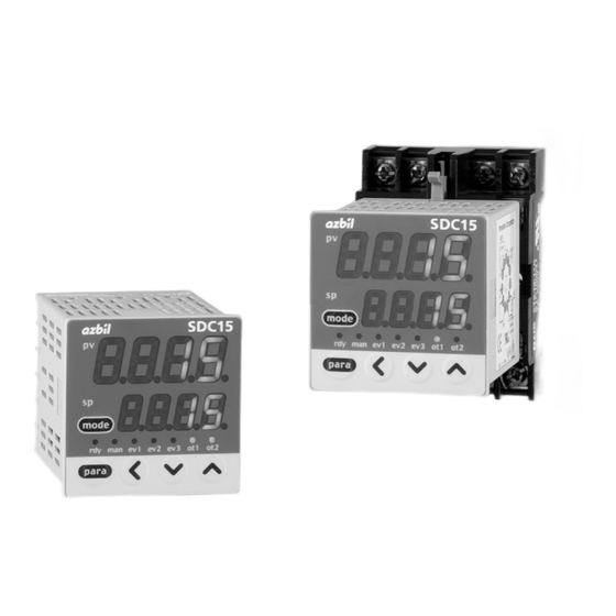
SDC15
Single Loop Controller
User's Manual
for
Basic Operation
Thank you for purchasing an Azbil
Corporation product.
This manual contains information for
ensuring the correct use of this product.
It also provides necessary information
for installation, maintenance, and trou-
bleshooting.
This manual should be read by those
who design and maintain equipment that
uses this product. Be sure to keep this
manual nearby for handy reference.
Advertisement

Related Manuals for Azbil SDC15


Summary of Contents for Azbil SDC15
- Page 1 No. CP-SP-1147E SDC15 Single Loop Controller User's Manual Basic Operation Thank you for purchasing an Azbil Corporation product. This manual contains information for ensuring the correct use of this product. It also provides necessary information for installation, maintenance, and trou- bleshooting.
- Page 2 If you should find an error or omis- sion, please contact the azbil Group. In no event is Azbil Corporation liable to anyone for any indirect, special or consequential damages as a result of using this product.
- Page 3 SAFETY REQUIREMENTS To reduce risk of electric shock which could cause personal injury, follow all safety notices in this documentation. This symbol warns the user of a potential shock hazard where hazardous live voltages may be accessible. If the equipment is used in a manner not specified by the manufacturer, the protection •...
- Page 4 SAFETY PRECAUTIONS ■ About Icons The safety precautions described in this manual are indicated by various icons. Please be sure you read and understand the icons and their meanings described below before reading the rest of the manual. Safety precautions are intended to ensure the safe and correct use of this prod- uct, to prevent injury to the operator and others, and to prevent damage to proper- ty.
- Page 5 WARNING Do not disassemble the SDC15. Doing so might cause electric shock or faulty operation. Before wiring, or removing/mounting the SDC15, be sure to turn the power OFF. Failure to do so might cause electric shock. Do not touch electrically charged parts such as the power terminals.
- Page 6 CAUTION The part between the control output 1 and control output 2 is not isolated. When necessary, use an appropriate isolator. Do not connect multiple loader cables to multiple units from one personal computer. The current coming from other circuits might cause the PV value indication error to occur.
- Page 7 The Role of This Manual Five different manuals in total are available for the SDC15 Single Loop Controller (hereafter referred to as "this unit"). Read appropriate manuals according to your requirements. If you do not have your required manual, contact the azbil Group or its dealer. Additionally, you can download necessary manuals from "http://www.azbil.com".
- Page 8 Organization of This User's Manual This manual is organized as follows: Chapter 1. OVERVIEW This chapter describes the applications, features, model selection guide, and part names and functions of this unit. Since the part names described in this chapter are used in the subsequent descriptions, the part names and functions of this unit must be understood correctly in this chapter.
- Page 9 Contents SAFETY REQUIREMENTS SAFETY PRECAUTIONS Important Notice The Role of This Manual Organization of This User's Manual Conventions Used in This Manual Chapter 1. OVERVIEW 1-1 Overview • • • • • • • • • • • • • • • • • • • • • • • • • • • • • • • • • • • • • • • • • • • • • • • • • • • • • • • • • • • • • • • • • • • ■...
- Page 10 Chapter 5. SETTINGS BEFORE STARTING OPERATION 5-1 PV Input • • • • • • • • • • • • • • • • • • • • • • • • • • • • • • • • • • • • • • • • • • • • • • • • • • • • • • • • • • • • • • • • • • • ■...
- Page 11 6-2 Operation Display other than SP • • • • • • • • • • • • • • • • • • • • • • • • • • • • • • • • • • • • • • • • • • • ■...
- Page 12 Chapter 9. MAINTENANCE AND TROUBLESHOOTING ■ Maintenance • • • • • • • • • • • • • • • • • • • • • • • • • • • • • • • • • • • • • • • • • • • • • • • • • • • • • • • • • • • ■...
- Page 13 The following conventions are used in this manual: Handling Precautions : Handling Precautions indicate items that the user should pay attention to when handling the SDC15. Note : Notes indicate useful information that the user might benefit by knowing. : This indicates the item or page that the user is requested to refer to.
- Page 15 Chapter 1. OVERVIEW 1 - 1 Overview This unit is a compact controller having a mask of 48 X 48 mm and provides the following features: • The depth is only 60 mm, providing the excellent space-saving. • The front panel is only 2 mm thick. This ensures the excellent thin design. •...
- Page 16 Chapter 1. OVERVIEW ■ Model selection table The following shows the model selection table of this unit: Basic Control Power Additional Mounting PV input Option Specifications model No. output supply treatment Panel mount type (Note 1) Socket mount type Control output 1 Control output 2 (Note 2) Relay contact output NO Relay contact output NC...
- Page 17 Chapter 1. OVERVIEW ■ Accessories and optional parts Name Model No. Mounting bracket (for C15T) 81446403-001 (Accessory) Gasket 81409657-001 (Accessory) Current transformer (800 turns, 5.8mm hole dia.) QN206A* Current transformer (800 turns, 12mm hole dia.) QN212A* Socket (for C15S) 81446391-001 Hard cover 81446442-001 Soft cover...
- Page 18 Chapter 1. OVERVIEW 1 - 2 Part Names and Functions ■ Main body and console Console SDC15 Upper display Lower Display [mode] key mode Mode indicator para [para] key [<], [ ], and [ ] keys Console Main body Main body: Contains the electric circuit for I/O signals of measuring instruments, CPU, and memory.
- Page 19 Chapter 1. OVERVIEW Upper display This display shows the PV value or the name of each display item (display value or set value). If an alarm occurs in the operation display mode, the normal display and alarm code are displayed alternately. The decimal point at the right end digit shows AT (auto tuning) or ST (self- tuning) status.
- Page 20 Chapter 1. OVERVIEW ■ Rear panel ● Panel mount type Terminal part Terminal part: The power supply, input, and output are connected to the terminals. The M3 screw is used. When connecting to the terminal, always use a correct crimp terminal suitable for the M3 screw. The tightening torque of the terminal screw is 0.4 to 0.6N·m.
- Page 21 Chapter 2. OUTLINE OF FUNCTIONS 2 - 1 Input/Output Configuration Other Analog Control output PV input Control output 1, 2 process process process (Current output) (ON/OFF control, Internal PID control) contact Digital input 1, 2 process Control output 1, 2 (Relay output, voltage pulse output) Internal...
- Page 22 Chapter 2. OUTLINE OF FUNCTIONS 2 - 2 Key Operation The following shows the flow of the general key operation. Various displays and settings can be called up to the console. Display when the power is turned ON. The mode indicators are lit sequentially Off.
- Page 23 Chapter 2. OUTLINE OF FUNCTIONS Handling Precautions • For details about display and setup contents of the operation display, parameter setting display, and setup setting display, refer to 7-1 List of Operation Displays (on page 7-1), 7-2 List of Parameter Setting Displays (on page 7-2) and 7-3 List of Setup Setting Displays (on page 7-5).
- Page 24 Chapter 2. OUTLINE OF FUNCTIONS (3) Do not press the key for 2 sec. >> The flashing display is stopped, and then the data you have changed is set. mode mode Handling Precautions • If the data does not start flashing even though the [<], [ ], or [ ] key is pressed, this data cannot be changed.
- Page 25 Chapter 2. OUTLINE OF FUNCTIONS ■ [mode] key operating procedures When the [mode] key is kept pressed for 1 sec. or longer on the operation display, the selection operation, which has been set using the [mode] key function ([C72]) of the setup setting, can be performed. The Figure on the right shows an example that the [mode] key is pressed in the RUN/READY selection ([C72] = 2) setting.
- Page 26 Chapter 2. OUTLINE OF FUNCTIONS 2 - 3 Operation Modes The following shows the transition of operation modes. RUN + AUTO mode AT stop ST stop READY + AUTO mode RUN/READY AT running ST running selection AT stop ST stop AUTO/MANUAL selection AUTO/MANUAL selection RUN + MANUAL mode...
- Page 27 Chapter 3. INSTALLATION CAUTION Use the SDC15 within the operating ranges recommended in the specifications (temperature, humidity, voltage, vibration, shock, mounting direction, atmosphere, etc.). Failure to do so might cause fire or faulty operation. Do not block ventilation holes. Doing so might cause fire or faulty operation.
- Page 28 Chapter 3. INSTALLATION ■ External Dimensions ● Panel Mount type (C15T) Unit: mm Mounting bracket (Accessory) Terminal screw SDC15 mode para ● Socket Mount type (C15S) Socket 81446391-001 (Optional unit) 74.2 Terminal screw 61.2 M3.5 26.5 SDC15 2-M4 mounting hole...
- Page 29 Chapter 3. INSTALLATION ■ Mounting procedures • The mounting must be horizontal within 10 degrees tilted in back side lowering or within 10 degrees tilted in back side rising. • In the case of panel mount type (C15T), the mounting panel should be used with a thickness of less than 9 mm of firm board.
- Page 30 Chapter 3. INSTALLATION ● Using the hard cover for panel mount type (C15T) For panel mounting type, it is possible to attach the hard cover to the front console. Use of hard cover makes it possible to prevent the settings from being changed due to accidental operation or to operate the unit in poor installation environment.
- Page 31 Chapter 3. INSTALLATION ● Using the soft cover for panel mount type (C15T) For the panel mounting type, it is possible to attach the soft cover to the front console. The key can be operated with the soft cover attached. Attaching the soft cover to the front console provides the protection (IP66) similar to the waterproof mounting using the gasket.
- Page 32 Chapter 3. INSTALLATION ● Socket mount type (C15S) Items to be prepared: Phillips-head screwdriver Socket DIN rail Stopper hole Main body Stopper The above Figure shows the DIN rail mounting. (1) Mount the socket inside the panel. (For screw tightening, mount the socket directly.) (2) Perform the wiring to the socket.
- Page 33 WIRING 4 - 1 Wiring WARNING Before wiring, or removing/mounting the SDC15, be sure to turn the power OFF. Failure to do so might cause electric shock. Do not touch electrically charged parts such as the power terminals. Doing so might cause electric shock.
- Page 34 Chapter 4. WIRING ■ Terminal assignment label symbols The following table shows the meanings of the symbols used for the terminal assignment label attached to the side panel of this unit. Symbol Contents Caution, Electric shock hazard Caution ■ Wiring Precautions •...
- Page 35 Chapter 4. WIRING • The part between the control output 1 and control output 2 is not isolated. When necessary, use an appropriate isolator. Important • Do not connect any terminating resistor to both ends of the RS-485 communication path. Doing so might cause the communication to fail. •...
- Page 36 Chapter 4. WIRING ● Wiring of C15S Control output Event output Relay Relay Voltage pulse Relay independent contact Current Power supply PV input Current 100 to 240Vac Voltage 24Vac / 24 to 48Vdc (non-polarity) Thermocouple Socket terminal No. ● Recommended crimp type terminal lugs For C15T, use an appropriate crimp type terminal lug suitable for the M3 screw.
- Page 37 Chapter 4. WIRING ■ Connection of open collector output to digital input ■ Connection of (RS-485) communication cable ● 3-wire system This unit (slave station) Master station Shield This unit (slave station) Shield Important • Do not connect any terminating resistor to both ends of the communication path.
- Page 38 Chapter 4. WIRING ● 5-wire system This unit (slave station) Master station Shield This unit (slave station) Shield Important • Do not connect any terminating resistor to both ends of the communication path. Doing so might cause the communication to fail.
- Page 39 1. Azbil Corporation's PGM10N/PGM10F series This example shows the calculation for the connection of the SDC15 and the PGM10N015. (Note: For connection with other model number, check the specifications of each model.)
- Page 40 Chapter 4. WIRING 2. Omron's G3PA, G3PB, G3NA • Input current: Since the input current is 7mA or less, up to three units (7mA X 3 = 21mA < 24mA [maximum allowable current]) can be connected in parallel. • Operating voltage range (input): The rating voltage is 5 to 24Vdc or 12 to 24Vdc.
- Page 41 When necessary, an appropriate external resistor is connected in series so that the voltage between the input terminals of the SSR you are using is within the specified range. (Example) Connection of two Azbil Corporation PGM units Connection diagram External resistor R1 V: 19V ±...
- Page 42 If the noise from the power supply is large, an appropriate insulation transformer is added to the power supply and an appropriate line filter is used. (Azbil Corporation's line filter model No.: 81442557-001) If the noise has fast rising edge, an appropriate CR filter is used.
- Page 43 Chapter 4. WIRING 4 - 2 Recommended Cables Contact the thermocouple wires to the terminals in case of a thermocouple input. When a thermocouple is connected to terminals, or wiring distance is long, connect the wire via a shielded compensating lead wire. •...
- Page 45 Chapter 5. SETTINGS BEFORE STARTING OPERATION CAUTION Do not operate the key with a propelling pencil or sharp-tipped object. Doing so might cause faulty operation.
- Page 46 Chapter 5. SETTINGS BEFORE STARTING OPERATION 5 - 1 PV Input The PV input type, temperature unit, decimal point position, and PV input range low limit and high limit of the PV input are set. There may be some items you cannot set up depending on the input type (T: Thermocouple, R: RTD, L: DC current or DC voltage) or PV range type of the model.
- Page 47 For details on the decimal point, refer to; SDC15 Single Loop Controller User's Manual for Installation & Configuration CP-SP-1148E. • Make sure to set the correct number in setup display C01, according to the type and range of the sensor used.
- Page 48 Chapter 5. SETTINGS BEFORE STARTING OPERATION ■ Temperature unit setup (1) In the operation display mode, keep the [para] key pressed for 2 sec. or longer. >> The unit then enters the parameter setting mode. mode para (2) In the parameter setting display mode, keep the [para] key pressed for 2 sec.
- Page 49 Chapter 5. SETTINGS BEFORE STARTING OPERATION ■ Decimal point position setup (1) In the operation display mode, keep the [para] key pressed for 2 sec. or longer. >> The unit then enters the parameter setting mode. mode para (2) In the parameter setting display mode, keep the [para] key pressed for 2 sec.
- Page 50 Chapter 5. SETTINGS BEFORE STARTING OPERATION ■ PV input range low limit/high limit setup (1) In the operation display mode, keep the [para] key pressed for 2 sec. or longer. >> The unit then enters the parameter setting mode. mode para (2) In the parameter setting display mode, keep the [para] key pressed for 2 sec.
- Page 51 Chapter 5. SETTINGS BEFORE STARTING OPERATION 5 - 2 Control The control method, control action (Direct/Reverse), heat/cool control selection, and heat/cool control deadband are set. ■ Control method setup (1) In the operation display mode, keep the [para] key pressed for 2 sec. or longer. >>...
- Page 52 Chapter 5. SETTINGS BEFORE STARTING OPERATION ■ Control action (Direct/Reverse) setup (1) In the operation display mode, keep the [para] key pressed for 2 sec. or longer. >> The unit then enters the parameter setting mode. mode para (2) In the parameter setting display mode, keep the [para] key pressed for 2 sec.
- Page 53 Chapter 5. SETTINGS BEFORE STARTING OPERATION ■ Heat/Cool control selection setup (1) In the operation display mode, keep the [para] key pressed for 2 sec. or longer. >> The unit then enters the parameter setting mode. mode para (2) In the parameter setting display mode, keep the [para] key pressed for 2 sec.
- Page 54 Chapter 5. SETTINGS BEFORE STARTING OPERATION ■ Heat/Cool control dead band setup (1) In the operation display mode, keep the [para] key pressed for 2 sec. or longer. >> The unit then enters the parameter setting mode. mode para (2) In the parameter setting display mode, keep the [para] key pressed for 2 sec.
- Page 55 Deadband = 0.0 % Heat/cool control change point = 50.0 % Heat/cool control change point = 75.0 % SDC15 Single Loop Controller User's Manual for Installation & Configuration, No. CP-SP-1148E (13th edition or later) Handling Precautions • When the parameter setting [Ctrl: Control method] is set at [0: ON/OFF control], [C28] is not displayed.
-
Page 56: Lsp System Group 1 To
Chapter 5. SETTINGS BEFORE STARTING OPERATION ■ LSP system group setup (1) In the operation display mode, keep the [para] key pressed for 2 sec. or longer. >> The unit then enters the parameter setting mode. mode para (2) In the parameter setting display mode, keep the [para] key pressed for 2 sec. - Page 57 Chapter 5. SETTINGS BEFORE STARTING OPERATION 5 - 3 Internal Event In "Simple configuration", the internal event must be set when using the event output, an additional function of the model. In "Simple configuration", the operation type, Direct/Reverse, standby, MV in READY mode, main setting, and sub-setting of the internal event can be set.
- Page 58 Chapter 5. SETTINGS BEFORE STARTING OPERATION Operation type Set value Direct action Reverse action ● shows that the ON/OFF is changed at this value. ● shows that the ON/OFF is changed at this value. of operation ❍ shows that the ON/OFF is changed at a point that ❍...
- Page 59 Chapter 5. SETTINGS BEFORE STARTING OPERATION Operation type Set value Direct action Reverse action of operation type Loop diagnosis 1 The event is turned ON when any change in PV corresponding to increase/decrease in MV (Manipulated variable) is not observed. This event is used to detect any fault at the operation end.
- Page 60 Chapter 5. SETTINGS BEFORE STARTING OPERATION Operation type Set value Direct action Reverse action of operation type Loop diagnosis 2 The event is turned ON when any change in PV corresponding to increase/decrease in MV (Manipulated variable) is not observed. This event is used to detect any fault at the operation end.
- Page 61 Chapter 5. SETTINGS BEFORE STARTING OPERATION Operation type Set value Direct action Reverse action of operation type Loop diagnosis 3 The event is turned ON when any change in PV corresponding to increase/decrease in MV (Manipulated variable) is not observed. This event is used to detect any fault at the operation end.
- Page 62 Chapter 5. SETTINGS BEFORE STARTING OPERATION Operation type Set value Direct action Reverse action of operation type Alarm ON if alarm occurs (alarm code AL01 to 99). OFF if alarm occurs (alarm code AL01 to 99). (status) OFF in other cases. ON in other cases.
- Page 63 Chapter 5. SETTINGS BEFORE STARTING OPERATION ■ Event operation type setup (1) In the operation display mode, keep the [para] key pressed for 2 sec. or longer. >> The unit then enters the parameter setting mode. mode para (2) In the parameter setting display mode, keep the [para] key pressed for 2 sec.
- Page 64 Chapter 5. SETTINGS BEFORE STARTING OPERATION ■ Event Direct/Reverse, standby, and Event state at READY setup (1) In the operation display mode, keep the [para] key pressed for 2 sec. or longer. >> The unit then enters the parameter setting mode. mode para (2) In the parameter setting display mode, keep the [para]...
- Page 65 Chapter 5. SETTINGS BEFORE STARTING OPERATION ■ Event main setting setup (1) In the operation display mode, keep the [para] key pressed for 2 sec. or longer. >> The unit then enters the parameter setting mode. mode para (2) Press the [para] key several times. >>...
- Page 66 Chapter 5. SETTINGS BEFORE STARTING OPERATION ■ Event sub-setting setup (1) In the operation display mode, keep the [para] key pressed for 2 sec. or longer. >> The unit then enters the parameter setting mode. mode para (2) Press the [para] key several times. >>...
- Page 67 Chapter 5. SETTINGS BEFORE STARTING OPERATION ■ Event hysteresis setup (1) In the operation display mode, keep the [para] key pressed for 2 sec. or longer. >> The unit then enters the parameter setting mode. mode para (2) Press the [para] key several times. >>...
-
Page 68: 0: Heater Burnout Detection 1: Current Value Measurement
Chapter 5. SETTINGS BEFORE STARTING OPERATION 5 - 4 CT (Current Transformer) Input The following settings are necessary when using the CT (Current Transformer) input of the optional model. For CT input, two kinds of current values are provided. • Current value at output ON: This value is used for the heater burnout/over-current event. The value is displayed as CT current value. -
Page 69: 0: Control Output 1
Chapter 5. SETTINGS BEFORE STARTING OPERATION ■ CT output setup (1) In the operation display mode, keep the [para] key pressed for 2 sec. or longer. >> The unit then enters the parameter setting mode. mode para (2) n the parameter setting display mode, keep the [para] key pressed for 2 sec. -
Page 70: To 300 Ms
Chapter 5. SETTINGS BEFORE STARTING OPERATION ■ CT wait time before measurement setup (1) In the operation display mode, keep the [para] key pressed for 2 sec. or longer. >> The unit then enters the parameter setting mode. mode para (2) In the parameter setting display mode, keep the [para] key pressed for 2 sec. - Page 71 Chapter 5. SETTINGS BEFORE STARTING OPERATION 5 - 5 Continuous Output The settings below are necessary when the control output of the model uses the current output. In a current range of 4 to 20mA or 0 to 20mA selected in [Output range], the current, that the value set in [Output type] is scaling-processed with [Output scaling low limit·high limit], is then output.
- Page 72 5: SP 6: Deviation 7: CT1 current value Scaled in units of 0.1A. 8: CT2 current value 9: MFB (invalid on SDC15) 10: SP+MV Scaled in the same unit of measure 11: PV+MV (ºC, etc.) as the PV. >> When no keys are pressed for 2 sec. or longer, the flashing of the numeric value is stopped to set the currently displayed value.
- Page 73 Chapter 5. SETTINGS BEFORE STARTING OPERATION ■ Output scaling low limit/high limit setup (1) In the operation display mode, keep the [para] key pressed for 2 sec. or longer. >> The unit then enters the parameter setting mode. mode para (2) In the parameter setting display mode, keep the [para] key pressed for 2 sec.
- Page 74 Chapter 5. SETTINGS BEFORE STARTING OPERATION ■ MV scaling range When the control output type is set to either SP+MV or PV+MV, the control output is a continuous output in which the amount of change in the MV is added to the SP or PV.
- Page 75 Chapter 5. SETTINGS BEFORE STARTING OPERATION 5 - 6 Communication The settings below are necessary when using the RS-485 communication, an optional function of the model. In "Simple configuration", the communication mode, station address, transmission speed, data format (data length), data format (parity), and data format (stop bit) are set.
- Page 76 Chapter 5. SETTINGS BEFORE STARTING OPERATION ■ Station address setup (1) In the operation display mode, keep the [para] key pressed for 2 sec. or longer. >> The unit then enters the parameter setting mode. mode para (2) In the parameter setting display mode, keep the [para] key pressed for 2 sec.
- Page 77 Chapter 5. SETTINGS BEFORE STARTING OPERATION ■ Transmission speed setup (1) In the operation display mode, keep the [para] key pressed for 2 sec. or longer. >> The unit then enters the parameter setting mode. mode para (2) In the parameter setting display mode, keep the [para] key pressed for 2 sec.
- Page 78 Chapter 5. SETTINGS BEFORE STARTING OPERATION ■ Data format (data length) setup (1) In the operation display mode, keep the [para] key pressed for 2 sec. or longer. >> The unit then enters the parameter setting mode. mode para (2) In the parameter setting display mode, keep the [para] key pressed for 2 sec.
- Page 79 Chapter 5. SETTINGS BEFORE STARTING OPERATION ■ Data format (parity) setup (1) In the operation display mode, keep the [para] key pressed for 2 sec. or longer. >> The unit then enters the parameter setting mode. mode para (2) In the parameter setting display mode, keep the [para] key pressed for 2 sec.
- Page 80 Chapter 5. SETTINGS BEFORE STARTING OPERATION ■ Data format (stop bit) setup (1) In the operation display mode, keep the [para] key pressed for 2 sec. or longer. >> The unit then enters the parameter setting mode. mode para (2) In the parameter setting display mode, keep the [para] key pressed for 2 sec.
- Page 81 Chapter 5. SETTINGS BEFORE STARTING OPERATION 5 - 7 Key Operation In “Simple configuration”, the mode key function and user level are set. ■ Mode key function setup (1) In the operation display mode, keep the [para] key pressed for 2 sec. or longer. >>...
- Page 82 >> The display is returned to the operation display. Handling Precautions When [User level] is set at [Standard configuration] or [High function configuration], the description of this manual is insufficient. In this case, refer to Single Loop Controller SDC15 User's Manual "Installation & Configurations" (CP-SP-1148E). 5-38...
- Page 83 Chapter 5. SETTINGS BEFORE STARTING OPERATION 5 - 8 DI Assignment The settings below are necessary when using DI (digital input), an optional function of the model. In "Simple configuration", the internal contact operation type is set. With the default settings before shipment, the DI has been directly connected to the internal contact process.
- Page 84 Chapter 5. SETTINGS BEFORE STARTING OPERATION (4) Press the [<], [ ], or [ ] key to change the value set in [dI1.1] to that you have selected from the following table: Set value Function Operation at OFF Operation at ON No function None None...
- Page 85 Chapter 6. SETTINGS DURING OPERATION 6 - 1 The SP can be set in either the operation display or parameter setting display mode. ■ SP setup in operation display mode (1) Make sure that the unit is in the operation display mode. If the unit is in the parameter setting display or setup setting display mode, press the [mode] key.
- Page 86 Chapter 6. SETTINGS DURING OPERATION ■ LSP No. setup (1) Make sure that the unit is in the operation display mode. If the unit is in the parameter setting display or setup setting display mode, press the [mode] key. >> The display is then returned to the operation display. (2) Make sure that the LSP No.
- Page 87 Chapter 6. SETTINGS DURING OPERATION ■ SP setup in parameter setting display mode (1) In the operation display mode, keep the [para] key pressed for 2 sec. or longer. >> The unit then enters the parameter setting mode. mode para (2) Press the [para] key several times.
- Page 88 Chapter 6. SETTINGS DURING OPERATION 6 - 2 Operation Display other than SP With "Simple configuration", the MV (manipulated variable) setting, heat MV (manipulated variable), cool MV (manipulated variable), AT progress, and CT (current transformer) inputs 1 and 2 are displayed. ■...
- Page 89 Chapter 6. SETTINGS DURING OPERATION ■ Heat MV (manipulated variable) and cool MV (manipulated variable) display (1) Make sure that the unit is in the operation display mode. If the unit is in the parameter setting display or setup setting display mode, press the [mode] key.
- Page 90 Chapter 6. SETTINGS DURING OPERATION ■ CT (current transformer) input 1/2 current value display (1) Make sure that the unit is in the operation display mode. If the unit is in the parameter setting display or setup setting display mode, press the [mode] key.
- Page 91 Chapter 6. SETTINGS DURING OPERATION 6 - 3 Mode In “Simple configuration", AUTO/MANUAL mode selection, RUN/READY mode selection, AT (auto tuning) Stop/Start selection, release all DO (digital output) latches, and communication DI (digital input) 1 OFF/ON selection can be set. However, the operation by the communication DI1 cannot be set only in "Simple configuration".
- Page 92 Chapter 6. SETTINGS DURING OPERATION ■ RUN/READY mode selection setup (1) In the operation display mode, keep the [para] key pressed for 2 sec. or longer. >> The unit then enters the parameter setting mode. mode para (2) In the parameter setting display mode, press the [para] key.
- Page 93 Chapter 6. SETTINGS DURING OPERATION ■ AT (auto tuning) Stop/Start selection setup (1) In the operation display mode, keep the [para] key pressed for 2 sec. or longer. >> The unit then enters the parameter setting mode. mode para (2) Press the [para] key several times. >>...
- Page 94 Chapter 6. SETTINGS DURING OPERATION ■ Release all DO (digital output) latches setup (1) In the operation display mode, keep the [para] key pressed for 2 sec. or longer. >> The unit then enters the parameter setting mode. mode para (2) Press the [para] key several times.
- Page 95 Chapter 6. SETTINGS DURING OPERATION ■ Communication DI (digital input) 1 setup (1) In the operation display mode, keep the [para] key pressed for 2 sec. or longer. >> The unit then enters the parameter setting mode. mode para (2) Press the [para] key several times. >>...
- Page 96 Chapter 6. SETTINGS DURING OPERATION 6 - 4 In this unit, the number of PID groups is one. When [CtrL: Control method] is set at “0” (ON/OFF control), the PID cannot be set. In "Simple configuration", P-1 (Proportional band), I-1 (Integral time), D-1 (Derivative time), rE-1 (Manual reset), P-1C (P (Proportional band) (cool)), I-1C (I (Integral time) (cool)), and d-1c (D (Derivative time) (cool)) can be set.
- Page 97 Chapter 6. SETTINGS DURING OPERATION ■ I-1 (Integral time) setup (1) In the operation display mode, keep the [para] key pressed for 2 sec. or longer. >> The unit then enters the parameter setting mode. mode para (2) Press the [para] key several times. >>...
- Page 98 Chapter 6. SETTINGS DURING OPERATION ■ d-1 (Derivative time) setup (1) In the operation display mode, keep the [para] key pressed for 2 sec. or longer. >> The unit then enters the parameter setting mode. mode para (2) Press the [para] key several times. >>...
- Page 99 Chapter 6. SETTINGS DURING OPERATION ■ rE-1 (Manual reset) setup (1) In the operation display mode, keep the [para] key pressed for 2 sec. or longer. >> The unit then enters the parameter setting mode. mode para (2) Press the [para] key several times. >>...
- Page 100 Chapter 6. SETTINGS DURING OPERATION ■ P-1C (Proportional band - cool) setup (1) In the operation display mode, keep the [para] key pressed for 2 sec. or longer. >> The unit then enters the parameter setting mode. mode para (2) Press the [para] key several times. >>...
- Page 101 Chapter 6. SETTINGS DURING OPERATION ■ I-1C (Integral time - cool) setup (1) In the operation display mode, keep the [para] key pressed for 2 sec. or longer. >> The unit then enters the parameter setting mode. mode para (2) Press the [para] key several times. >>...
- Page 102 Chapter 6. SETTINGS DURING OPERATION ■ d-1C (Derivative time - cool) setup (1) In the operation display mode, keep the [para] key pressed for 2 sec. or longer. >> The unit then enters the parameter setting mode. mode para (2) Press the [para] key several times. >>...
- Page 103 Chapter 6. SETTINGS DURING OPERATION 6 - 5 Other Parameter Setup In "Simple configuration", the ON/OFF control differential, PV filter, PV bias, time proportional cycle time 1/2, MV low limit and high limit at AT (auto tuning), key lock, password display, and password 1A to 2B can be set. ■...
- Page 104 Chapter 6. SETTINGS DURING OPERATION ■ PV filter setup The PV filter (primary filter with the software) is activated to remove the noise from the PV input. (1) In the operation display mode, keep the [para] key pressed for 2 sec. or longer. >>...
- Page 105 Chapter 6. SETTINGS DURING OPERATION ■ PV bias setup The PV bias is activated to correct the PV input error. (1) In the operation display mode, keep the [para] key pressed for 2 sec. or longer. >> The unit then enters the parameter setting mode. mode para (2) Press the [para] key several times.
- Page 106 Chapter 6. SETTINGS DURING OPERATION ■ Time proportional cycle time 1/2 setup (1) In the operation display mode, keep the [para] key pressed for 2 sec. or longer. >> The unit then enters the parameter setting mode. mode para (2) Press the [para] key several times. >>...
- Page 107 Chapter 6. SETTINGS DURING OPERATION ■ MV low limit/high limit at AT (auto tuning) (1) In the operation display mode, keep the [para] key pressed for 2 sec. or longer. >> The unit then enters the parameter setting mode. mode para (2) Press the [para] key several times.
- Page 108 PV indirectly and is intended for the adjustment aiming at the stability. • When compared to the AT function of Azbil Corporation’s conventional model, the results similar to the SDC10 are obtained when the set value “1” (immediate response) is set and the results similar to the SDC20/21 are obtained when the set value “0”...
- Page 109 Chapter 6. SETTINGS DURING OPERATION ■ Key lock setup (1) In the operation display mode, keep the [para] key pressed for 2 sec. or longer. >> The unit then enters the parameter setting mode. mode para (2) In the parameter setting display mode, keep the [para] key pressed for 2 sec.
- Page 110 Chapter 6. SETTINGS DURING OPERATION ■ Password lock function This controller has a password lock function using a password in addition to the key lock function. It offers a double security so that the key lock setting itself cannot be changed by unauthorized operators. In password lock function, the setting to disable the change in key lock function cannot be displayed.
- Page 111 Chapter 6. SETTINGS DURING OPERATION ■ Password display setup (1) In the operation display mode, keep the [para] key pressed for 2 sec. or longer. >> The unit then enters the parameter setting mode. mode para (2) In the parameter setting display mode, keep the [para] key pressed for 2 sec.
- Page 112 Chapter 6. SETTINGS DURING OPERATION ■ Passwords (1A, 2A, 1B, 2B) setup (1) In the operation display mode, keep the [para] key pressed for 2 sec. or longer. >> The unit then enters the parameter setting mode. mode para (2) In the parameter setting display mode, keep the [para] key pressed for 2 sec.
- Page 113 Chapter 7. LIST OF SIMPLE CONFIGURATION DISPLAY ITEMS 7 - 1 List of Operation Displays Display Item Contents Initial value Notes Display No.1: PV SP (Target value) SP low limit (C07) to Display No.2: SP SP high limit (C08) LSP No. (1st digit: Value 1 to LSP system group (Max. 4) Displayed when [LSP system at the right end digit) group] (C30) is 2 or more.
- Page 114 Chapter 7. LIST OF SIMPLE CONFIGURATION DISPLAY ITEMS 7 - 2 List of Parameter Setting Displays Display Item Contents Initial value Notes AUTO/MANUAL AUTO Displayed when the control method is mode selection other than ON/OFF control (CtrL ≠ 0). : AUTO mode : MANUAL mode RUN/READY mode selection...
- Page 115 Chapter 7. LIST OF SIMPLE CONFIGURATION DISPLAY ITEMS Display Item Contents Initial value Notes Event 3 main setting Same as Event 1 main / sub setting Event 3 sub setting Event 3 hysteresis Same as Event 1 hysteresis Event 4 main setting Same as Event 1 main / sub setting Event 4 sub setting Event 4 hysteresis...
- Page 116 Chapter 7. LIST OF SIMPLE CONFIGURATION DISPLAY ITEMS Display Item Contents Initial value Notes Time proportional 5 to 120s (when the output includes Displayed when the heat/cool control cycle time 2 (cool) the relay output) is used. 1 to 120s (when the output does not When the output destination of the tim include the relay output) proportional output 2 includes the relay...
-
Page 117: Table Of Contents
Chapter 7. LIST OF SIMPLE CONFIGURATION DISPLAY ITEMS 7 - 3 List of Setup Setting Displays Display Item Contents Initial value Notes PV input range type When the PV input type is thermocouple: For details, refer to the PV input 1 to 6, 9 to 11, 13 to 21, 24, 25 range table (on page 5-3). - Page 118 CT. When the output 1 type is 7: CT1 current value related to the PV, SP, and deviation, 8: CT2 current value the decimal point position becomes 9: MFB (invalid on SDC15) the same as that of the PV. 10: SP+MV 11: PV+MV Output 1 scaling...
- Page 119 Chapter 7. LIST OF SIMPLE CONFIGURATION DISPLAY ITEMS Display Item Contents Initial value Notes Communication mode 0: CPL Displayed when the optional model 1: MODBUS (ASCII format) has RS-485. 2: MODBUS (RTU format) Station address 0 to 127 Displayed when the optional model Communication is disabled when "0"...
- Page 120 Chapter 7. LIST OF SIMPLE CONFIGURATION DISPLAY ITEMS Display Item Contents Initial value Notes Operation type of 0: No event internal event 1 1: PV high limit 2: PV low limit 3: PV high/low limit 4: Deviation high limit 5: Deviation low limit 6: Deviation high/low limit 7: Deviation high limit (Final SP reference)
- Page 121 Chapter 7. LIST OF SIMPLE CONFIGURATION DISPLAY ITEMS Display Item Contents Initial value Notes Operation type of Same as operation type of internal internal event 2 event 1. Internal event 2 Same as internal event 1. 0000 1st digit: Direct/Reverse 2nd digit: Standby 3rd digit: Operation at READY...
- Page 122 Chapter 7. LIST OF SIMPLE CONFIGURATION DISPLAY ITEMS Display Item Contents Initial value Notes Operation type of Same as operation type of internal internal contact 2 contact 1 Operation type of Same as operation type of internal internal contact 3 contact 1 Key lock 0: All settings are enabled.
- Page 123 Chapter 8. PID CONTROL TUNING CAUTION This unit incorporates the self-tuning function without use of control constant settings in addition to the ON/OFF control and conventional PID control. This self-tuning control monitors and studies the characteristics of the control subject even if the SP value is changed or external disturbance occurs in order to automatically calculate the control constants.
- Page 124 Chapter 8. PID CONTROL TUNING 8 - 1 AT (auto tuning) Function The AT (auto tuning) function is used in the following cases: • The PID constants are set automatically with the control method set at “Fixed PID” ([CtrL = 1]). •...
- Page 125 Chapter 8. PID CONTROL TUNING ● Operation during execution of AT Insufficient stability Stable cycle Time AT start Normal end The AT function calculates the PID constants using the limit cycle. (1) When the AT function is started, a point, where the SP and PV deviations are split to “2:1”, is determined as ON/OFF change point of the MV (manipulated variable).
- Page 126 Chapter 8. PID CONTROL TUNING 8 - 2 ST (Self-tuning) Function When the following ST start conditions are satisfied with the control method set at ST ([CtrL] = 2), the ST function is started automatically to change the PID constants. (1) ST start by SP change If the SP is changed in the RUN mode, the ST function is started.
- Page 127 Chapter 8. PID CONTROL TUNING ■ Stopping procedures The ST is completed automatically. If it is necessary to stop the ST halfway during execution of the ST or not to start the ST during stopping of the ST, set the control method of the parameter setting to “Fixed PID”...
- Page 128 Chapter 8. PID CONTROL TUNING 8 - 3 Precautions for ST (Self-tuning) When using the ST function, the following cautions must be observed strictly: ● Before starting the ST function, put the PV input and operation end (heater power, etc.) in the controllable status. ●...
- Page 129 A/D conversion A/D converter is faulty. It is thought that the main body needs to failure be replaced. Contact the azbil Group or its dealer. AL95 Set data failure Data is corrupted by noise. Turn ON the power again. Power is shut-down while the data is If the same alarm occurs after that, set the being set.
- Page 130 Chapter 9. MAINTENANCE AND TROUBLESHOOTING ■ Operation in case of PV input failure (1) AL01, 02, or 03 occurs. Control output: It is possible to make the settings so that the operation is continued or discontinued. Other operation: Operation is continued. (2) Alarm occurs in cases other than those shown above.
- Page 131 Chapter 10. DISPOSAL When disposing of this unit, dispose of the unit properly as industrial waste according the applicable laws and regulations specified by the local governmental office. 10-1...
- Page 133 0.3 to 0.65mm diameter Allowablr input voltage: -0.5 to +12V Note: When the dedicated loader cable is connected to the SDC15, the temperature characteristics of the controller may be affected, but control is not. • RTD input Input bias current: Approx.
- Page 134 Chapter 11. SPECIFICATIONS ● Control output • Relay output Output rating: Control output 1 NO side 250Vac/30Vdc, 3A (resistance load) Control output 2 NC side 250Vac/30Vdc, 1A (resistance load) Life: 50,000 cycles or more on NO side 100,000 cycles or more on NC side Min.
- Page 135 Chapter 11. SPECIFICATIONS Display range lower limit: 0.0Aac Display range upper limit: 70.0Aac (800 turns, 1 time) Formula; Number of turns ÷ (16 x number of power wire loops) x 1.4 Display accuracy: ±5%FS Display resolution: 0.1Aac ● RS-485 communication Transmission line: 3-wire method Transmission speed:...
- Page 136 Power consumption: AC power model, Max. 12VA (8VA at 100Vac and 12VA at 264Vac) (When using the functions similar to those of Azbil Corporation’s SDC10, the power consumption is 6VA at 100Vac and 9VA at 264Vac.) DC power model, Max. 7VA (24Vac), Max. 5W (24 to 48Vdc)
- Page 137 (Control outputs of relay and voltage pulse, and event output) Event Local Set Point. The meaning of LSP and SP is same in case of the SDC15. Motor Feed Back. This indicates the feed back of motor opening which is used for position proportional control.
- Page 139 Index -Number- 3-wire system • • • • • • • • • • • • • • • • • • • • • • • • • • • • • • • • • • Data format setup 5-33, 5-34, 5-35 5-wire system •...
- Page 140 IEC directive Noise preventive measures 4-10 • • • • • • • • • • • • • • • • • • • • • • • • • • • • • • • • • • •...
- Page 141 Sampling cycle time 11-1 • • • • • • • • • • • • • • • • • • • • • • • • • • • Self-tuning function • • • • • • • • • • • • • • • • • • • • • • • • • • • • Setup setting display •...
- Page 142 Dust-proof and drip-proof performance to degrees of protection changed. 5th Edition APPLICABLE STANDARDS: Oct. 2007 EN61326-1→EN61326 changed. Description on SDC15 Quick Reference Guide added. L-shaped plug adaptor added. ●PV input range table (Thermocouple): 7 of C01 set value deleted. 11-1 Allowable input voltage added on DC current input.
- Page 143 End of the manual Terms and Conditions were changed (to version No. AA511A-014-03). 8th Edition 1-3, 11-2, 11-4 A note was added to the specifications for current Mar. 2014 transformer input. 4-10 Azbil Corporation's line filter model No. was changed.
- Page 144 In the case of products that Azbil Corporation has repaired for a fee, the repaired part only shall be warranted for three (3) months from the time of delivery to the location designated by the customer.
- Page 145 Azbil Corporation's products every 5 to 10 years unless otherwise specified in specifications or instruction manuals.
- Page 146 Specifications are subject to change without notice. (09) 1-12-2 Kawana, Fujisawa Kanagawa 251-8522 Japan URL: http://www.azbil.com 1st edition: July 2003 (A) 8th edition: Mar. 2014 (F)
Need help?
Do you have a question about the SDC15 and is the answer not in the manual?
Questions and answers