Table of Contents
Advertisement
Quick Links
(Not for use in Japan)
No. CP-SP-1402E
Multi-loop Controller with
Multifunction Display
Model C7G
Installation and
Configuration Manual
Thank you for purchasing an Azbil
Corporation product.
This manual contains information for
ensuring the correct use of this product.
It also provides necessary information
for installation, maintenance, and
troubleshooting.
This manual should be read by those who
design and maintain equipment that uses
this product. Be sure to keep this manual
nearby for handy reference.
Advertisement
Table of Contents

Related Manuals for Azbil C7G


Summary of Contents for Azbil C7G
- Page 1 Multi-loop Controller with Multifunction Display Model C7G Installation and Configuration Manual Thank you for purchasing an Azbil Corporation product. This manual contains information for ensuring the correct use of this product. It also provides necessary information for installation, maintenance, and troubleshooting.
- Page 2 If you should find an error or omission, please contact the azbil Group. In no event is Azbil Corporation liable to anyone for any indirect, special or consequential damages as a result of using this product. © 2017-2018 Azbil Corporation. All Rights Reserved.
- Page 3 Safety Requirements To reduce the risk of an electric shock that could cause personal injury, follow all safety notices in this document. This symbol warns the user of a potential shock hazard where hazardous live voltages may be accessible. Use of this product in a manner not specified by the manufacturer will impair its built-in safety features. Do not replace any component except as specified by the manufacturer.
-
Page 4: Conventions Used In This Manual
Conventions Used in This Manual „ The safety precautions explained below aim to prevent injury to you and others, and to prevent property damage. Warnings are indicated when mishandling this WARNING product may result in death or serious injury. Cautions are indicated when mishandling this CAUTION product may result in minor injury or property damage only. -
Page 5: Safety Precautions
Safety Precautions WARNING Do not use this device in an environment with conductive pollution, or with dry non- conductive pollution which can become conductive due to condensation, etc. Otherwise, problems such as tracking phenomena may damage parts, resulting in fire. Make sure that the frame ground terminal is properly grounded (100 Ω... - Page 6 CAUTION Do not operate the buttons or the touch panel with a sharp object (such as a mechanical pencil tip, etc.). Doing so can cause device failure. The frame ground terminal of this device is a functional ground. Ground the frame ground terminal to suppress adverse effects from external noise.
-
Page 7: Copyright, Licenses, And Registered Trademarks
Copyright, licenses, and registered trademarks • Notice on use of licensed software of ARM. This product uses the software according to the license of ARM in a part of the software. The following contents are based on the license agreement, which does not prescribe customers’ usage restrictions. Copyright ©... -
Page 8: Table Of Contents
Contents Safety Requirements Conventions Used in This Manual Safety Precautions Copyright, licenses, and registered trademarks Chapter 1. Overview 1 - 1 Overview 1 - 2 Model No. Model Selection Guide „ Optional Parts (Sold Separately) „ 1 - 3 Names of Parts and Their Functions Display unit „... - Page 9 DI/DO block (7 digital inputs or outputs, selectable) „ RS-485 (RS-485 communication port) „ „ Analog input block (analog input) 3-10 Analog input block layout 3-11 „ Analog output block (current outputs, CT inputs, and VT inputs) 3-12 „ Voltage pulse output block (voltage pulse outputs and 2 CT inputs) 3-13 „...
- Page 10 Fixed value output 4-22 „ Special control output 4-23 „ „ When switching to MANUAL mode 4-23 PID control initialization 4-24 „ PID initial MV 4-24 „ MV change limit 4-25 „ PID control 4-25 „ „ AT (Auto-tuning) 4-26 SP lag 4-26 „...
- Page 11 4 - 10 DO (Digital Output) 4-65 DI/DO configuration 4-65 „ „ DO assignment 4-66 4 - 11 TP (Time Proportioning) Output 4-68 DI/DO configuration 4-69 „ TP output type 4-69 „ TP cycle 4-70 „ „ TP operation type 4-70 Linearization table group definition 4-71...
- Page 12 ON/OFF delay 4-100 „ 4 - 19 CDS (Compact Data Storage) 4-102 „ Recording cycle/operation type 4-102 Data selection 4-103 „ Number of data / Data1 to Data40 4-104 „ Screen during CDS operation 4-106 „ Files 4-107 „ „ Customizing the number of data items and data types 4-111 Setting the date and time by the SLP-C7...
- Page 13 AT start/stop screen 5-34 „ HOLD mode change screen 5-35 „ ADVANCE operation screen 5-36 „ „ G.SOAK clear screen 5-37 DI/DO monitor screen 5-38 „ DI monitor screen 5-39 „ DO monitor screen 5-40 „ EV monitor screen 5-41 „...
- Page 14 Graph bank 6-36 „ ETHERNET bank 6-36 „ „ IP ADDRESS bank 6-37 RS-485 bank 6-37 „ CDS bank 6-38 „ HEALTH INDEX bank 6-40 „ HEALTH INDEX graph 6-41 „ „ Date and time bank 6-41 Input assignment bank 6-42 „...
- Page 15 Multiple data write command (10H) „ 1 data write command (06H) „ 7 - 4 Numeric Value Expression Hexadecimal „ 7 - 5 Send/Receive Timing 7-10 Time specifications for instruction and response messages 7-10 „ Specifications of RS-485 driver control timing 7-10 „...
- Page 16 Chapter 10. PLC Link Communication 10-1 10 - 1 Data Transfer 10-1 „ Connectible PLCs 10-4 Usable devices 10-5 „ 10 - 2 PLC Link Setting Method 10-6 Common settings 10-6 „ Transfer settings 10-7 „ Transfer setting examples 10-8 „...
- Page 17 Chapter 14. Appendix 14-1 14 - 1 Function Block Diagrams 14-1 AI (analog input) process block diagram 14-1 „ „ SP process / PID process block diagram 14-2 „ AO (analog output) process block diagram 14-3 TP (time proportioning) output process block diagram 14-4 „...
-
Page 19: Overview
1 - 1 Overview The C7G multi-loop controller with multifunction display (hereafter also called simply "this device") can calculate diagnostic parameters, known collectively as the health index, that help to predict failure of other equipment, in addition to calculations for PID (proportional, integral and derivative) control of process variables such as temperature, pressure, flow rate, pH, and liquid level. -
Page 20: Model No
Chapter 1. Overview 1 - 2 Model No. Model Selection Guide „ Block name Symbol Block Name Description Analog input Full multi-range input (thermocouple, RTD, DC current, DC voltage) Voltage pulse Voltage pulse output (12 V DC) output 2 input terminals for the current transformer (CT) for detecting heater burnout, overcurrent, and short circuits* AO-C Analog current... - Page 21 Chapter 1. Overview Model C7G (UL-compliant) Example: C7GA411CC0DA0 Main unit Other Slots Slots Slots Slots Add'l Add'l Special Base model No. Comm. Size Option Description proc. spec. support Multi-loop controller with multifunction display Communication (Ethernet, RS-485, USB) 7 digital input/outputs (sink output, source input)
- Page 22 Chapter 1. Overview Model C7G (Not UL-compliant) Example: C7GA411CC0D00 Main unit Other Slots Slots Slots Slots Add'l Add'l Special Base model No. Comm. Size Option Description proc. spec. support Multi-loop controller with multifunction display Communication (Ethernet, RS-485, USB) 7 digital input/outputs (sink output, source input)
- Page 23 Chapter 1. Overview Model C7G with MOTOR Block (UL-compliant) Example: C7GA411MC0DA0 Main unit Other Slots Slots Slot Slot Add'l Add'l Special Base model No. Comm. Size Option Description proc. spec. support Multi-loop controller with multifunction display Communication (Ethernet, RS-485, USB)
- Page 24 Chapter 1. Overview Model C7G with MOTOR Block (Not UL-compliant) Example: C7GA411MC0D00 Main unit Other Slots Slots Slot Slot Add'l Add'l Special Base model No. Comm. Size Option Description proc. spec. support Multi-loop controller with multifunction display Communication (Ethernet, RS-485, USB)
-
Page 25: X84; Z Optional Parts (Sold Separately)
Chapter 1. Overview C7D Additional Display Unit Example: C7D-400D00 Main unit Other Option Option Add'l Add'l Special Base model No. Size Description proc. spec. support Additional display unit for multi-loop controller with multifunction display Integrated mounting* Standard mounting English, Japanese None None With inspection report... -
Page 26: Names Of Parts And Their Functions
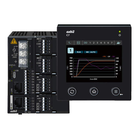
Chapter 1. Overview 1 - 3 Names of Parts and Their Functions Display unit „ LCD touch panel Power indicator (green for normal status) Terminal block Menu button Home button Main unit connector Change button Front Back Main unit „ DI/DO terminal block Power supply terminal block (with cover) -
Page 27: Input/Output Configuration
Chapter 1. Overview 1 - 4 Input/output Configuration Other Analog Analog output 1 to 4 output (Output by scaling the MV, process PV, and other using the Analog input 1 to 4 * PV process Control process* current output.)* (PID control, ON/OFF control) RSP process Internal cascade... - Page 28 Chapter 1. Overview Digital output (DO) Output functions such as event output that are set using the DO bank, or the time proportioning output function set using the TP (time proportioning) bank, can be used. Linear approximation is available for time proportioning output. CT (current transformer) input (block positions: A2, B2, A1, B1) The current can be measured by the input from the CT.
-
Page 29: Button Operation
Chapter 1. Overview 1 - 5 Button Operation Various kinds of data can be displayed or set using the buttons on the display unit screen and the buttons on the lower section of the display unit screen. Screen transitions „ When the power is turned on, the monitor screen is displayed. -
Page 30: X84; Z Parameter Bank
Chapter 1. Overview Parameter bank „ The order of the parameter banks and parameter items is shown by the tree structure below. Parameter bank Parameter item SP values of LSP1 to LSP8, RSP for loops 1 to 4 PID group number of LSP1 to LSP8, RSP for loops 1 to 4 EVENT Main setting for event groups 1 to 16 Sub-setting for event groups 1 to 16... - Page 31 Chapter 1. Overview Parameter bank Parameter item CONTROL Control action for loops 1 to 4 Differential for ON/OFF control for loops 1 to 4 Heating/cooling control dead zone for loops 1 to 4 PID initial MV for loops 1 to 4 PID initialization for loops 1 to 4 Type of change to MANUAL for loops 1 to 4 Preset MANUAL value for loops 1 to 4...
- Page 32 Chapter 1. Overview Parameter bank Parameter item TP output type of DO groups 4 to 7 and blocks A2, B2, A1, and B1 TP output cycle of DO groups 4 to 7 and blocks A2, B2, A1, and B1 TP operation type of DO groups 4 to 7 and blocks A2, B2, A1, and B1 Linearization table group definition of DO groups 4 to 7 and blocks A2, B2, A1, and B1...
- Page 33 Chapter 1. Overview Parameter bank Parameter item LINEARIZATION TABLE Operation type of linearization table groups 1 to 8 10 break points of linearization table groups 1 to 8 CASCADE Scaling method Scaling low limit Scaling high limit Filter PATTERN CONFIG Pattern start number for loops 1 to 4 Pattern start number low limit for loops 1 to 4 Pattern start number high limit for loops 1 to 4...
- Page 34 Chapter 1. Overview Parameter bank Parameter item DATE TIME Year, month, day, hour, minutes, and seconds INPUT ASSIGNMENT PV assignments for loops 1 to 4 RSP assignment for loops 1 to 4 Assignment range low limit for loops 1 to 4 Assignment range high limit for loops 1 to 4 VIRTUAL ANALOG INPUT Virtual AI assignment of virtual AI 1 to 4...
-
Page 35: X84; Z Monitor And Graph Screen Transitions
Chapter 1. Overview Monitor and graph screen transitions „ For 1 loop Power-on Home button The home screen is the 1-loop monitor screen. 1-loop monitor screen (LOOP1) Graph icon Numeric icon 1-loop graph screen (LOOP1) 1-17... - Page 36 Chapter 1. Overview For 2 loops Power-on Home button The home screen is the multi-loop monitor screen. Touch the display of each loop. Multi-loop 1-loop monitor 1-loop monitor monitor screen screen screen (LOOP1 to 2) (LOOP1) (LOOP2) Change button Graph icon Numeric icon Touch the PV No.
- Page 37 Chapter 1. Overview For 3 loops Power-on Home button The home screen is the multi-loop monitor screen. Touch the display of each loop. Multi-loop 1-loop monitor 1-loop monitor 1-loop monitor monitor screen screen screen screen (LOOP1 to 3) (LOOP1) (LOOP2) (LOOP3) Change button Graph icon...
- Page 38 Chapter 1. Overview For 4 loops Power-on Home button The home screen is the multi-loop monitor screen. Touch the display of each loop. Multi-loop 1-loop monitor 1-loop monitor 1-loop monitor 1-loop monitor screen screen screen screen monitor screen (LOOP1) (LOOP2) (LOOP3) (LOOP4) (LOOP1 to 4)
-
Page 39: X84; Z Screen Transitions Of The User Home Screen
Chapter 1. Overview Screen transitions of the user HOME screen „ From the loops set to be used in the loop type setting, enable the loop to be displayed on the user HOME screen with the following settings. Item (bank) Display Description Initial value... - Page 40 Chapter 1. Overview The "HOME screen layout" setting (left/right split, left/right swap, vertically arranged) also applies to the 2-loop screen. The 3-loop screen is vertically arranged regardless of the "HOME screen layout" setting. If the graph icon on the user HOME screen is touched, the display changes to the graph screen.
-
Page 41: Operation Modes
Chapter 1. Overview 1 - 6 Operation Modes Up to four loops can be controlled individually. The operation modes can also be changed individually or all together. The following shows the transition of the operation modes. RUN + AUTO mode READY + AUTO mode Constant value operation Constant value operation... - Page 42 Chapter 1. Overview Constant value operation: Process control uses the LSP or RSP. Pattern operation: Process control uses the pattern SP (the SP is generated from the segment setting stored in the measuring instrument). RUN: Control execution status (the three statuses of RUN, RUN-HOLD, and RUN-END in the case of pattern operation) READY: Control stop status...
-
Page 43: Mounting
Chapter 2. Mounting 2 - 1 External View and Mounting Dimensions Standard mounting „ Unit: mm Display unit Main unit Other device Panel cutout (front) +1.5 (3.6) Hole Φ30 ±0.2 −0 4×Φ3.6 Hole ±0.2 100.5 17.3 ±0.3 Standard gasket DIN rail holder * Wiring hole * Dimensions when pulled out Other device... -
Page 44: Mounting Method
Chapter 2. Mounting 2 - 2 Mounting Method Standard mounting „ Main unit Mount the main unit on a DIN rail with a width of 35 mm. Check that the DIN rail holding tab on the main unit is pushed in. Hook the catches on the upper back of the main unit onto the DIN rail and press the main unit until it clicks into place. - Page 45 Chapter 2. Mounting (3) Hold the setscrews firmly from the back of the panel and screw the display unit mounting screws into the remaining mounting screw holes. Two types of display unit mounting screws (M3 machine screws) are supplied with the product. Select appropriate screws according to the thickness of the control panel.
- Page 46 Chapter 2. Mounting (5) Further tighten the four display unit mounting screws. (Tightening torque: 0.6 N·m) (6) Connect the display unit and the display unit connector on the main unit using the LAN cable. LAN cable...
-
Page 47: X84; Z Integrated Mounting
Chapter 2. Mounting Integrated mounting „ Main unit After mounting the display unit on the control panel, mount the main unit on the main unit mounting rail of the integrating bracket. Display unit To mount the display unit on the control panel, follow the steps below. Be sure to mount the display unit securely on the integrating bracket using the display unit mounting screws (M3 machine screws) included with the product. - Page 48 Chapter 2. Mounting (3) Working from the front of the control panel, pass the integrating cable and the upper part of the integrating bracket through the cutout in the panel. (4) Raise the display unit, pass the bottom part of the integrating bracket through the cutout in the panel, and hang it on the connecting part of the setscrews.
- Page 49 Chapter 2. Mounting Handling Precautions • Tightening the screws excessively may deform the display unit and control panel or prevent proper use of the touch panel and buttons. • When the display unit is used for a waterproof application, be sure to mount the gasket with 92 ×...
- Page 50 -MEMO-...
-
Page 51: Wiring
Chapter 3. Wiring 3 - 1 Wiring Precautions WARNING Do not use this device in an environment with conductive pollution, or with dry non- conductive pollution which can become conductive due to condensation, etc. Otherwise, problems such as tracking phenomena may damage parts, resulting in fire. Before removing, mounting, or wiring the device, be sure to turn off the power to this device and any connected devices. -
Page 52: X84; Z Wiring Precautions
Chapter 3. Wiring Wiring precautions „ • Be sure to mount a switch for shutoff of the main power to this device within reach of the operator. Add this switch to the wiring on the non-grounded side. • The following table shows the meaning of the symbols printed on the main unit. Symbol Description Caution: risk of electrical shock... -
Page 53: Recommended Cables
Chapter 3. Wiring 3 - 2 Recommended Cables • For the thermocouple input, after crimping the bare thermocouple lead on the ferrule, connect it to the terminal block. If the wiring distance is long or if the thermocouple uses a terminal connection, extend the lead wires using compensating lead wires to connect them to the terminals. -
Page 54: Crimp Terminals
Chapter 3. Wiring 3 - 3 Crimp Terminals Crimp terminals „ CAUTION Firmly tighten the terminal screws to the torque listed in the specifications. Insufficient tightening may result in fire or electric shock. Do not use unused terminals as relay terminals. There is a danger of fire, electric shock, or device failure. - Page 55 Chapter 3. Wiring Recommended ferrules (for DI/DO, RS-485, AI, AO-C, V-P) Product Cross-sectional area Model Notes number AI 0,25-8 YE 3203037 0.25 (24 AWG) With insulation sleeve AI 0,34-8-TQ 3203066 0.34 (22 AWG) With insulation sleeve AI 0,5-8 WH 3200014 0.50 (20 AWG) With insulation sleeve AI 0,75-8 GY...
-
Page 56: Wiring
Chapter 3. Wiring 3 - 4 Wiring WARNING Before wiring, installing, or removing this device, be sure to shut off the power supply. Otherwise, there is a danger of electric shock. CAUTION Before handling the main unit and display unit or removing/inserting cables, touch a grounded panel to discharge any static electricity. -
Page 57: X84; Z Power Input
Chapter 3. Wiring Power input „ AC models 1: Live side of AC power supply 2: AC power neutral line 3: Frame ground DC models 1: DC power + 2: DC power − 3: Frame ground Handling Precautions • Before touching the power input terminal box, shut off the input power. •... -
Page 58: X84; Z Di/Do Block (7 Digital Inputs Or Outputs, Selectable)
Chapter 3. Wiring DI/DO block (7 digital inputs or outputs, selectable) „ z : N.C. (Do not connect to this terminal.) N1: DI/DO1 (DI/DO can be switched by changing the setting.) N2: DI/DO2 (DI/DO can be switched by changing the setting.) N3: DI/DO3 (DI/DO can be switched by changing the setting.) N4: DI/DO4 (DI/DO can be switched by changing the setting.) N5: DI/DO5 (DI/DO can be switched by changing the setting.) -
Page 59: Rs-485 Communication Port)
Chapter 3. Wiring • To use as DO or time proportional output: • Pay attention to the polarity of the external power supply. Reverse polarity connection may cause breakage. • An overcurrent protection circuit is incorporated. If an overcurrent is detected, the DO is forced OFF and an alarm is generated. -
Page 60: X84; Z Analog Input Block (Analog Input)
• If equipment controller devices that do not allow connection of a terminating resistor (such as Azbil Corporation's SDC15/25/26/35/36 and DMC10) are included in the transmission line, do not connect any terminating resistor to the external or communication lines of the C7G. -
Page 61: X84; Z Analog Input Block Layout
Chapter 3. Wiring Analog input block layout „ 1 loop C7G _ _ 10 _ _ _ _ _ _ C7G _ _ 20 _ _ _ _ _ _ C7G _ _ 11 _ _ _ _ _ _ LOOP1... -
Page 62: X84; Z Analog Output Block (Current Outputs, Ct Inputs, And Vt Inputs)
Chapter 3. Wiring 4 loops C7G _ _ 22 _ _ _ _ _ _ LOOP3 LOOP3 LOOP4 LOOP4 LOOP1 LOOP1 LOOP2 LOOP2 Handling Precautions • The AI value of an AI block that is not used for control cannot be monitored using the display or communication. -
Page 63: X84; Z Voltage Pulse Output Block (Voltage Pulse Outputs And 2 Ct Inputs)
Chapter 3. Wiring Handling Precautions • Do not connect or disconnect any load while the power of this device is on. Failure of this device or the load may result. • The CT, VT, and current outputs inside the same block are not isolated. •... -
Page 64: X84; Z Di Block (4 Digital Inputs)
Chapter 3. Wiring • When the current transformer input is used for phase angle control, the input accuracy of the product may not be satisfied. • If a current transformer is used for a UL-compliant model, the transformer must be compliant with UL 2808 (categories XOBA and XOBA7). Do not use an uncertified current transformer. -
Page 65: X84; Z Motor Block (Motor Drive Outputs And Motor Feedback Inputs)
Chapter 3. Wiring MOTOR block (motor drive outputs and motor feedback inputs) „ 1: OPEN Open 2: Common 3: CLOSE Close 4: MFB (Y) Open 5: MFB (T) 6: MFB (G) Close Contact rating For models other than UL-compliant models 2 A, 250 V AC (inductive load) 2.5 A, 24 V DC (inductive load) For UL-compliant models... -
Page 66: X84; Z I/O Isolation
Chapter 3. Wiring I/O isolation „ I/O isolation Internal Motor drive output Motor block circuits Power input Frame ground input DI/DO block AI block AO-C block Analog VT input CT input output V-P block Voltage RS-485 block pulse output CLOCK block HMI block HMI2 block DI block... -
Page 67: X84; Z Inserting Or Removing A Microsd Memory Card
Chapter 3. Wiring Inserting or removing a microSD memory card „ Insert the microSD memory card all the way inside. Pushing on the memory card lightly will enable you to remove the card. Handling Precautions • Do not insert or remove a memory card while the indicator next to the connector is flashing. -
Page 68: X84; Z Connecting The Cable Between The Main Unit And Display Unit
Chapter 3. Wiring Connecting the cable between the main unit and display unit „ Handling Precautions • Do not pull on the wires of the display unit excessively. Doing so may damage the connector. • Before connecting the display unit, turn off the power to the main unit. Standard mounting Use a Cat5E or higher straight LAN cable to make the connection. - Page 69 Chapter 3. Wiring Mounting of additional display unit Use a Cat5E or higher straight LAN cable to make the connection. (Cat5E, T568A, or T568B wiring. Both ends use an RJ45 plug (8P8C modular).) Handling Precautions • A 4-core LAN cable cannot be used. •...
- Page 70 Output current: 0.5 A min. Insulation between commercial power supply and 5 V DC: reinforced insulation LAN cable → To C7G main unit 5 V DC (+) 5 V DC (-) 5 V DC power supply To AC power supply ←...
-
Page 71: Chapter 4. Functions
Chapter 4. Functions 4 - 1 Loop Types This device has from 1 to 4 analog inputs (selected by model No.). For control execution, PV and RSP (remote SP) input can be assigned to any of the analog inputs in the [Loop type] settings. The loop type can be set by the SLP-C7 Smart Loader Package. - Page 72 Chapter 4. Functions 6th and 7th digits of the model No. (C7GA_ _ _ _ _ _ _ _ _ ) Loop type 5: 3 loops – – – A4: PV1 A4: PV1 A3: PV3 A3: PV3 B4: PV2 B4: PV2 B3: Unused 6: 3 loops + 1 RSP...
- Page 73 Chapter 4. Functions 6th and 7th digits of the model No. (C7GA_ _ _ _ _ _ _ _ _ ) Loop type 21: 4 loops + 4 RSPs – – – – – Handling Precautions • The value of an unused AI cannot be displayed. To display the value of the AI, even if it is not a control target, assign it to PV in the loop type.
-
Page 74: X84; Z Setting The Loop Type
(4) If [Write (SLP to C7)] is clicked on the toolbar, the SLP-C7 writes the loop type setting to the C7G along with other parameter settings. If the loop type is changed, the device restarts. Handling Precautions •... - Page 75 Chapter 4. Functions Note • 4 - 22 Advanced Loop Type Setting (p. 4-121) (for details on the advanced loop type setting and input assignments)
-
Page 76: Ai (Analog Input)
Chapter 4. Functions 4 - 2 AI (Analog Input) A maximum of 4 analog input points can be implemented. The following is a functional block diagram for analog input. For thermocouple For RTD For DC voltage/current Range type Range type Range type Scaling Alarm low and high limits... -
Page 77: X84; Z Range Types
Chapter 4. Functions Range types „ The setting is valid if the AI block is in the A4, B4, A3 or B3 slot. For thermocouple and resistance temperature detector, the sensor type and the temperature range can be selected. For DC voltage and DC current, the signal type can be selected. Item (bank) Display Description... -
Page 78: X84; Z Filter
(/, etc.) can be used. (5) Click [OK] to close the screen. (6) If [Write (SLP to C7)] is clicked on the toolbar, the SLP-C7 writes the characters set for the unit of measurement to the model C7G along with other parameter settings. Filter „... -
Page 79: X84; Z Ratio And Bias
Chapter 4. Functions Ratio and bias „ The setting is valid if the AI block is in the A4, B4, A3 or B3 slot. Input scaling can be used if the range type is set to DC voltage or DC current. Item (bank) Display Description... -
Page 80: X84; Z Sampling Cycle
Chapter 4. Functions Configuration is possible for any range type of thermocouple, resistance temperature detector, DC voltage, or DC current. Even if the number of decimal places for PV is changed, the decimal point position for the linear scaling and LSP in the AI bank does not change. The decimal point position is set so that the entire value does not exceed 5 digits. - Page 81 Chapter 4. Functions Handling Precautions • If the sampling cycle is 10 ms, or if CT input or VT input is used, set the power supply frequency for the region where the product will be used. If a different power supply frequency is set, the specifications for analog input indication accuracy may not be satisfied.
-
Page 82: Mode
Chapter 4. Functions 4 - 3 Mode Up to four loops can be controlled individually by this device. The following mode selections are available for each control loop. • AUTO/MANUAL mode selection • Constant value operation / Pattern operation selection •... -
Page 83: X84; Z Constant Value Operation / Pattern Operation
Chapter 4. Functions • Method 2: (1) Press the [„] (mode) button on the 1-loop monitor screen. > The mode selection screen appears. (2) Press the [MANUAL] button on the right side of AUTO/MANUAL. > The confirmation screen for changing the mode to AUTO appears. (3) Press the [AUTO] button. -
Page 84: X84; Z Run/Ready Mode
Chapter 4. Functions RUN/READY mode „ You can switch between the RUN and READY modes for each control loop in the constant value operation mode. RUN → READY (1) Press the [„] (mode) button on the 1-loop monitor screen. > The mode selection screen appears. (2) Press the [RUN] button in the right side of RUN/READY. -
Page 85: X84; Z Pattern Start Number
Chapter 4. Functions Handling Precautions • The number of LSP buttons to be displayed is set according to the number set in the LSP setting system. • The master side of the internal cascade control is fixed in LSP mode. •... - Page 86 Chapter 4. Functions RUN → READY (1) Press the [„] (mode) button on the 1-loop monitor screen. > The mode selection screen appears. (2) Press the [RUN] button to the right of "RUN/READY." > The confirmation screen for changing the mode to READY appears. (3) Press the [READY] button.
-
Page 87: X84; Z Advance
Chapter 4. Functions END → READY (1) Press the [„] (mode) button on the 1-loop monitor screen. > The mode selection screen appears. (2) Press the [RUN] button to the right of "RUN/READY." > The confirmation screen for changing the mode to READY appears. (3) Press the [READY] button. -
Page 88: X84; Z G.soak Clear
Chapter 4. Functions G.SOAK clear „ In the pattern operation mode, the G.SOAK wait state can be canceled individually for each control loop. (1) Press the [„] (mode) button on the 1-loop monitor screen. > The mode selection screen appears. (2) Press the [PATTERN] button in the upper left corner of the screen. -
Page 89: Control
Chapter 4. Functions 4 - 4 Control PID control or ON/OFF control can be provided for a maximum of 4 loops. The following is a functional block diagram of the respective controls. Functional block diagram of PID control „ PID control In MANUAL mode Branching by AUTO/MANUAL mode Bumpless/preset selection... -
Page 90: X84; Z Functional Block Diagram Of Heating/Cooling Control
Chapter 4. Functions Functional block diagram of heating/cooling control „ PID1 Switch between heating/cooling PID constants P, I, D (heat) Heat when 50% ≥ MV PID2 Cool when 50% < MV Cool P, I, D OL, OH (heat) PID8 Cool OL, OH PID group selection PID calculation AT stop... -
Page 91: X84; Z Heating/Cooling Control Dead Zone
Chapter 4. Functions Heating/cooling control dead zone „ The dead zone for heating and cooling control can be set for each control loop. Item (bank) Display Description Initial value Heating/cooling control MENU > Control -100.00 to +100.00 % 0.0000 dead zone (CONTROL bank) Heat/Cool control dead zone The Heat MV and Cool MV are output based on the MV that was output by the PID control calculation. -
Page 92: X84; Z Fixed Value Output
Chapter 4. Functions Fixed value output „ Fixed value output selected by DI (digital input) can be output instead of the MV from PID control. There are eight fixed value output settings for each loop, and they can be selected by the sum of the weights of the digital inputs. However, when the sum of the weights is "0,"... -
Page 93: X84; Z Special Control Output
Chapter 4. Functions Special control output „ The output in READY mode and the output when there is a PV alarm can be set for each control loop. Item (bank) Display Description Initial value READY MV (CONTROL bank) MENU > Control -10.000 to +110.00% 0.0000 READY MV... -
Page 94: X84; Z Pid Control Initialization
Chapter 4. Functions PID control initialization „ When changing the LSP or switching SP groups, the manipulated variable (MV) may be stuck at the low or high limit, the PV may be resistant to change, or the PV may overshoot. PID control initialization is effective in preventing these problems. It can be set for each control loop. -
Page 95: X84; Z Mv Change Limit
Chapter 4. Functions MV change limit „ The amount of MV change can be limited for each control loop. Item (bank) Display Description Initial value MV increase change limit MENU > Control 0.0000: No limit 0.0000 (CONTROL bank) MV increase change limit 0.0001 to 10000 %/s MV decrease change limit MENU >... -
Page 96: At (Auto-Tuning)
Chapter 4. Functions AT (Auto-tuning) „ The settings related to AT can be set for each control loop. Item (bank) Display Description Initial value MV low limit during AT MENU > Control -10.000 to +110.00 % 0.0000 (CONTROL bank) MV low limit during AT MV high limit during AT MENU >... -
Page 97: X84; Z On/Off Control
Chapter 4. Functions Handling Precautions • If the firmware version of the MAIN block is 1.x.x (where x stands for any number), the SP lag does not operate even though it can be set. „ ON/OFF control The settings related to ON/OFF control can be configured for each control loop. Item (bank) Display Description... -
Page 98: At (Auto-Tuning)
Chapter 4. Functions 4 - 5 AT (Auto-tuning) Up to four loops can be controlled individually. Use the AT function to set the PID constants automatically. „ How to start (1) Make sure that the PV (analog input) and the actuators (heater power, etc.) are ready for control. - Page 99 Chapter 4. Functions AT abnormal end If AT does not start after the AT start operation, or if AT stops without changing the PID constants even though there was no AT stop operation, an AT abnormal end is generated and the data of the corresponding loop among the standard bit codes for "AT abnormal end"...
- Page 100 Chapter 4. Functions • While AT is running, the MV turns on and off several times to execute the limit cycle. ("Off" here refers to the fact that the MV is limited by the MV low limit during AT and by the MV low limit, and the factory setting is 0 %. Also, "on" refers to the fact that the MV is limited by the MV high limit during AT and by the MV high limit, and the factory setting is 100 %.) If there is a problem with this operation, do either of the following.
- Page 101 Chapter 4. Functions 4 - 6 Up to four loops can be controlled individually. The following is a functional block diagram for set points. Number of LSP system groups RSP range type Pattern operation For two or more LSP groups For one LSP group RSP high and low limit alarm...
-
Page 102: X84; Z Setting The Lsp From The 1-Loop Monitor Screen
Chapter 4. Functions Setting the LSP from the 1-loop monitor screen „ (1) Press the [SP] button on the 1-loop monitor screen. > The SP change screen appears. (2) Press the Change button on the right side of "LSP_VALUE." > The LSP value setting screen appears. (3) Enter a value using the numeric keypad, and press the [ENTER] button to set the LSP that is being used (from among LSP1 to 8) to that value. -
Page 103: X84; Z Lsp1 To 8 And Rsp
Chapter 4. Functions LSP1 to 8 and RSP „ It is possible to set 8 LSP groups for control loops. The RSP value can be displayed. Item (bank) Display Description Initial value LSP1 SP MENU > SP −32000 to +32000 0.0000 (SP bank) LSP1 / SP... -
Page 104: X84; Z Lsp Group No
Chapter 4. Functions LSP group No. „ The LSP group number can be set for each control loop. (1) Press the [SP] button on the 1-loop monitor screen. > The SP change screen appears. (2) Press the Change button on the right side of "LSP/RSP." >... -
Page 105: X84; Z Sp Ramp Unit
Chapter 4. Functions Item (bank) Display Description Initial value Loop definition MENU > DI When the operation type is other than (DI bank) Loop definition timer stop/start selection, 0: All loops collectively 1: Loop 1 2: Loop 2 3: Loop 3 4: Loop 4 When the operation type is timer stop/ start selection,... -
Page 106: X84; Z Sp Ramp Up And Down Slopes
Chapter 4. Functions SP ramp up and down slopes „ The up and down slopes of SP ramp can be set for each control loop. Item (bank) Display Description Initial value LSP ramp up slope MENU > SP Config 0: No slope 0.0000 (SP configuration bank) LSP ramp up slope... -
Page 107: X84; Z Sp Low And High Limits
Chapter 4. Functions SP low and high limits „ The SP low and high limits can be set for each control loop in order to specify the SP range. Item (bank) Display Description Initial value SP low limit MENU > SP Config −32000 to +32000 -32000 (SP configuration bank) -
Page 108: Pattern Operation
Chapter 4. Functions 4 - 7 Pattern Operation Pattern operations in which the SP changes over time, as shown in the figure, are available. A pattern consists of multiple segments, and each segment is determined by the specified SP and time. For each segment, a PID group number, G.SOAK (guaranteed soak), and a segment event can also be set. -
Page 109: X84; Z Number Of Patterns
Chapter 4. Functions Number of patterns „ Whether to allow or prohibit pattern operation can be set for all patterns and loops. Item Description Initial value Number of patterns 0: Do not use pattern operation. 1: 16 patterns × 16 segments Handling Precautions •... - Page 110 Chapter 4. Functions The following figure shows an example of the SP and time settings and the change of the SP. A change in the SP results in a straight line connecting the SP set for the previous segment and the SP for the relevant segment. Segment2 Segment3 Segment1...
-
Page 111: X84; Z Pid Group Number
Chapter 4. Functions PID group number „ PID group number can be set for each segment. For Segment 1, groups 1 to 8 can be set. For the group setting of Segment 2 and later segments, “0” to “8” can be set. If 0 is set, the PID group for the segment is the same as that of the previous segment. - Page 112 Chapter 4. Functions G.SOAK wait period G.SOAK wait period canceled G.SOAK width G.SOAK width G.SOAK time Time Segment2 Segment3 Segment1 G.SOAK at the start of a segment The G.SOAK wait period starts at the beginning of the segment and the pattern stops progressing.
-
Page 113: X84; Z Segment Event
Chapter 4. Functions Segment event „ Aside from internal events, 16 segment events for pattern operation are available. Only one segment event can be set to be ON for each segment. Segment events that are not set are OFF by default. Item Display Description... -
Page 114: X84; Z Cycle
Chapter 4. Functions Handling Precautions • When operation is brought back to the start of a pattern by the cycle function, PV start is not executed. • When PV start is enabled in the next pattern linked by the pattern link function, PV start is executed. -
Page 115: X84; Z End Of Operation
Chapter 4. Functions Handling Precautions • If cycle operation is set for the source of a link, the pattern link operates after the cycle operation is completed. • If the pattern number of the link source is set for the pattern link, the pattern will be repeated endlessly. -
Page 116: X84; Z Pattern Start Number
Chapter 4. Functions Pattern start number „ The pattern start number can be set for each loop. There are two ways to select the pattern number when the mode switches from READY to RUN, i.e., when pattern operation starts. • The pattern start number can be set on the display unit screen or via communication. -
Page 117: X84; Z Pattern Sp Increase/Decrease Change Limit
Chapter 4. Functions Example: Selecting patterns 1 to 3 for Loop 1 and patterns 11 and 12 for Loop 2 using DI1 and DI2 Set as in the following table. Setting Setting details (Operation performed by the setting) “Pattern selection (0/+1)” is set for The sum of the pattern numbers DI1, specifying “All loops. - Page 118 Chapter 4. Functions Handling Precautions • ADVANCE cannot be executed when the pattern SP increase change limit is something other than 0.0000 or the pattern SP decrease change limit is something other than 0.0000. • SP change continues even in the RUN-HOLD or RUN-END mode or during a G.SOAK wait period if the pattern SP change limit is active.
-
Page 119: Di (Digital Input)
Chapter 4. Functions 4 - 8 DI (Digital Input) The following is a functional block diagram for digital input. ON/OFF status of a terminal set to DI in the DI/DO con guration bank, or ON/OFF status of a standard bit code (ON/OFF status of DI block terminals is included in standard bit codes) DI with the No. -
Page 120: X84; Z Di Assignment
Chapter 4. Functions DI assignment „ Items related to DI groups 1 to 32 can be set using DI assignment in the DI settings. Item (bank) Display Description Initial value Operation type of DI groups MENU > DI 0: No function 1 to 32 Operation type 1: LSP group selection (0/+1) - Page 121 Chapter 4. Functions Item (bank) Display Description Initial value Input type of DI groups 1 MENU > DI 0: Always OFF to 32 Input type 1: Always ON (DI bank) 2 to 10: Reserved 11: DI1 12: DI2 13: DI3 14: DI4 15: DI5 16: DI6...
- Page 122 Chapter 4. Functions • For the "Linearization table group selection" operation type, the group number is the value obtained by adding the sum of the weights (+1, +2, +4) of the DIs that are set to ON to the setting value of the linearization table group definition.
- Page 123 Chapter 4. Functions The table below shows the operations for each operation type. Set value Operation type Operation at OFF Operation at ON No function Not available Not available LSP group selection (0/+1) LSP number: +0 LSP number: +1 LSP group selection (0/+2) LSP number: +0 LSP number: +2 LSP group selection (0/+4)
- Page 124 Chapter 4. Functions Set value Operation type Operation at OFF Operation at ON HOLD HOLD clear HOLD G.SOAK clear None G.SOAK clear 64–65 Reserved Not available Not available Constant value operation / pattern Constant value operation (the Pattern operation (the rising edge operation mode selection (edge) falling edge from ON to OFF is from OFF to ON is valid)
-
Page 125: Events
Chapter 4. Functions 4 - 9 Events The following is a functional block diagram for events. Operation type and loop de nition Direct/reverse, standby Event main setting, event subsetting, hysteresis ON-delay, OFF-delay READY mode operation Event status (ON/OFF) Handling Precautions •... -
Page 126: X84; Z Operation
Chapter 4. Functions Operation „ The operation of events is shown below. It differs depending on the operation type, direct/reverse setting, event main setting, event subsetting, hysteresis settings, etc. Event operation list Operation type Operation Direct action Reverse action ● means that ON/OFF changes at that ●... - Page 127 Chapter 4. Functions Operation type Operation Direct action Reverse action ● means that ON/OFF changes at that ● means that ON/OFF changes at that type setting value value ◯ means that ON/OFF changes after ◯ means that ON/OFF changes after that value is passed that value is passed Deviation high and low...
- Page 128 Chapter 4. Functions Operation type Operation Direct action Reverse action ● means that ON/OFF changes at that ● means that ON/OFF changes at that type setting value value ◯ means that ON/OFF changes after ◯ means that ON/OFF changes after that value is passed that value is passed Standard numerical...
- Page 129 Chapter 4. Functions Operation type Operation Direct action Reverse action type setting PV change rate Sets the change rate high or low limit for the event main setting. Measures the PV for each sampling cycle (in seconds) set in the event subsetting, and compares the high limit change in the PV with the change rate high limit or low limit to determine whether to turn the event on or off.
- Page 130 Chapter 4. Functions Operation type Operation Direct action Reverse action type setting Standard numerical Sets the change rate high or low limit for the event main setting, and sets the code sampling cycle for the event subsetting. Sets the standard numerical code for the Loop definition.
-
Page 131: X84; Z Operation Type And Loop Definition
Chapter 4. Functions Operation type and Loop definition „ The operation type can be set for an event. A total of 16 events is available from loops 1 to 4. Item (bank) Display Description Initial value Operation type MENU > EventConfig 0: No event (Event configuration bank) Operation type... -
Page 132: X84; Z Direct/Reverse, Standby, And Ready Mode Operation
Chapter 4. Functions Handling Precautions • If the operation type is set to Alarm (status), the loop definition setting is disabled, and regardless of the loop, the event is turned on when an alarm occurs, and the event is turned off when there is no alarm. •... - Page 133 Chapter 4. Functions This is an operation example for when the event type is set to "5: Deviation low limit event." The actual event is turned on or off, as shown in the figure below, based on the event standby settings. READY/RUN switching or power-on Hysteresis SP + Event main setting...
-
Page 134: X84; Z Event Main Setting, Event Subsetting, Hysteresis, Delay
Chapter 4. Functions Event main setting, event subsetting, hysteresis, delay „ The event main setting, event subsetting, hysteresis, and ON and OFF delays associated with the event operation type can be set. A total of 16 events is available for loops 1 to 4. Item (bank) Display Description... -
Page 135: Do (Digital Output)
Chapter 4. Functions 4 - 10 DO (Digital Output) The following is a functional block diagram for DO (digital output). DI/DO terminal set to DO in the DI/DO con guration setting or DO block terminal A certain event number or standard bit code is set for the output type of the above terminal in the DO settings ON/OFF status of the above event or standard bit code When OFF... -
Page 136: X84; Z Do Assignment
Chapter 4. Functions DO assignment „ For the DI/DO terminals whose operation type is set to DO in the DI/DO configuration bank and the terminals in the DO block, the output type can be set in the DO configuration bank. DI/DO Item (bank) Display... - Page 137 Chapter 4. Functions Block A1, B1 Item (bank) Display Description Initial value Block A1 MENU > DO Config 0: OFF DO1 to 4 output type BLOCK A1 / DO1 / Output 1 to 10: Reserved type (DO bank) 11: Event 1 MENU >...
-
Page 138: Tp (Time Proportioning) Output
Chapter 4. Functions 4 - 11 TP (Time Proportioning) Output The following is a functional block diagram for TP (time proportioning) output and ON/OFF control output. For DO4 to DO7 in the DI/DO block TP is set to DI/DO with a certain No. using the DI/DO con guration setting. -
Page 139: X84; Z Di/Do Configuration
Chapter 4. Functions DI/DO configuration „ Set the operation of the desired DI/DO number to TP. Four settings are available for DI/DO groups 4 to 7. Item (bank) Display Description Initial value Operation MENU > DI/DO Config 0: DI (DI/DO configuration bank) Operation type 1: DO 2: TP (time proportioning) output ←Select this... -
Page 140: X84; Z Tp Cycle
Chapter 4. Functions TP cycle „ The TP (time proportioning) cycle can be set to the DI/DO number and V-P output used for TP (time proportioning) output. Four settings are available for DI/DO groups 4 to 7, and four settings are available for blocks A2, B2, A1, and B1. -
Page 141: X84; Z Linearization Table Group Definition
Chapter 4. Functions Linearization table group definition „ The linearization table group used for TP (time proportioning) output linear approximation can be set. Four settings are available for DI/DO groups 4 to 7, and four settings are available for blocks A2, B2, A1, and B1. The linearization table group selections made by DI (digital input) can be combined in the case of blocks A2, B2, A1, and B1. -
Page 142: Analog Output (Ao)
Chapter 4. Functions 4 - 12 Analog Output (AO) A maximum of 4 analog output points can be implemented on this device. The following is a functional block diagram for analog output (AO). Output type and loop de nition Linear approximation Output scaling low and high limits Output range Analog output (current output) -
Page 143: X84; Z Loop Definition
Chapter 4. Functions Loop definition „ The setting is valid if the AO-C block is in the A2, B2, A1, or B1 slot. The loop definition can be set for analog output. Item (bank) Display Description Initial value Loop definition MENU >... -
Page 144: X84; Z Linearization Table Group Definition
Chapter 4. Functions Linearization table group definition „ The setting is valid if the AO-C block is in the A2, B2, A1, or B1 slot. The linearization table group used for linear approximation of analog output can be set. It is also possible to combine the linearization table group selection by DI (digital input). -
Page 145: Motor Drive Output (Position Proportional Control)
Chapter 4. Functions 4 - 13 Motor Drive Output (Position Proportional Control) In this device, implementation of a maximum of one motor drive output is possible. The function block diagram of the motor drive output (position proportional control) is shown below. Output type Motor drive block: MFB input Fully closed MFB count,... -
Page 146: X84; Z Control Method
Chapter 4. Functions Control method „ The setting is valid if a MOTOR block is inserted (using four slots) into the I/O slot. The control method of the motor drive output can be set. Item (bank) Display Description Initial value Control method selection MENU >... -
Page 147: Mfb At (Mfb Auto-Tuning)
Chapter 4. Functions Handling Precautions • Execute MFB AT (MFB auto-tuning) when using settings 0 and 1. • Accurately set "Full opening time" when using settings 2 and 3. • Factors that tend to result in the Estimating MFB status when using setting 0 include improper MFB adjustment, deterioration of the motor feedback potentiometer, poor resolution, and improper MFB input wiring connections. -
Page 148: X84; Z Mfb Adjustment Value
Chapter 4. Functions (2) The MFB AT status can be viewed on the 1-loop monitor screen. (3) Setting "Auto-tuning" to 0 (auto-tuning stop) stops MFB AT. MFB AT can also be stopped by pressing the [MFB AT STOP] button on the 1-loop monitor screen. -
Page 149: X84; Z Dead Zone
Chapter 4. Functions If MFB AT ends and the "Auto-tuning" setting changes to 3 (Auto-tuning has been completed), the settings for "Fully closed MFB count," "Fully open MFB count," and "Full opening time" are completed. Handling Precautions • If "Control method selection" is set to 0 or 1, the settings for "Fully closed MFB count,"... -
Page 150: X84; Z Linearization Table Group Definition
Chapter 4. Functions Linearization table group definition „ The setting is valid if a MOTOR block is inserted (using four slots) into the I/O slot. The linearization table used for linear approximation of motor drive output can be set. The linearization table group selections made by DI (digital input) cannot be combined. -
Page 151: Ct (Current Transformer) Input
Number of wire loops • For the number of turns, set the number of turns of the CT connected to the model C7G. • For the number of power wire loops, set the number of times that the electric wire passes through the hole in the CT. For example, if the electric wire passes through the hole of the CT twice as shown below, set "2."... -
Page 152: X84; Z Ct Input Display Range And Current Measurement Range
Chapter 4. Functions CT input display range and current measurement range „ The display range and the current measurement range of the CT input vary according to the number of turns inside the CT and the number of power wire loops through the CT. -
Page 153: X84; Z Current Measurement And Error Detection
Chapter 4. Functions Current measurement and error detection „ The V-P (voltage pulse) blocks each have two CT inputs, and can be used for continuous current measurement or heater and actuator burnout detection, overcurrent detection, and short circuit detection. Settings for both CT1 input and CT2 input groups must be made for each block: A2, B2, A1, and B1. - Page 154 Chapter 4. Functions CT operation When set to "0: Continuous current measurement," the current is measured regardless of whether V-P block output is ON or OFF. When set to "1: Detection of heater burnout for terminal OUT," different types of current value are measured depending on whether V-P block output is ON or OFF.
- Page 155 Chapter 4. Functions CT measurement wait time If "CT operation" is set to "1: Detection of heater burnout for terminal OUT," the time from the change in the output ON/OFF status to the start of the current value measurement can be set. After the ON/OFF of the monitored OUT terminal changes, measurement of the current value is started once the measurement wait time has elapsed.
- Page 156 Chapter 4. Functions Short-circuit detection current value If the measured current when output is OFF exceeds the setting, a short-circuit is detected. If the setting is 0.0, the detection function is stopped. Note • As a general guide, the set value should be midway between the normal current value and the short-circuit current value.
- Page 157 Chapter 4. Functions Note • If "heater burnout detection," "Overcurrent detection," and "Short-circuit detection" are set to ON (detection status), ON (detection status) is retained even if the delay timer reset conditions are satisfied. To set to OFF (disabled), set to the "no current measurement" status. •...
-
Page 158: X84; Z Condition For Restoring Status Before Measurement
Chapter 4. Functions Condition for restoring status before measurement „ Set the standard bit code as the determining condition for restoring the CT value to the "no current measurement" status. This function is used to cancel burnout detection that continues while control has stopped after burnout is detected. -
Page 159: Vt (Voltage Transformer) Input
Chapter 4. Functions 4 - 15 VT (Voltage Transformer) Input For models with VT (voltage transformer) input, voltage can be measured by the VT input. Also, the resistance of the actuator (heater) connected to the output of the AO-C block can be calculated from the voltage measured using VT input and the current measured using CT input. -
Page 160: Linear Approximation
Chapter 4. Functions 4 - 16 Linear Approximation Linear approximation can be used for analog input, analog output, time proportioning output, and position proportioning output. There are eight linearization groups. Each linearization group has 10 setting points. Two types of linear approximation are available, one by specifying breakpoints and another by specifying the bias, and the type is selected using the "Operation type"... -
Page 161: X84; Z Linearization By Specifying Bias
Chapter 4. Functions Linearization by specifying bias „ The input values for linear approximation are the breakpoint settings A1 to A10, the bias values for linear approximation are the breakpoint settings B1 to B10, and the output values are A1 + B1 to A10 + B10, and these appear as shown in the graph below. -
Page 162: X84; Z Example Using Linear Approximation For Analog Output
Chapter 4. Functions (2) Set the linearization table. Item (bank) Display Description Initial value Operation type MENU > Linearization Table 0: Breakpoint (Linearization table bank) Operation type 1: Bias Breakpoint A1 MENU > LinearizationTable -32000 (Linearization table bank) Breakpoint A1 Breakpoint A2 MENU >... - Page 163 Chapter 4. Functions (1) Specify the groups of the linearization table in the analog output bank. • BLOCK A2 Item (bank) Display Description Initial value Linearization table group definition MENU > AnalogOutput No linearization (ANALOG OUTPUT bank) Linearization table group 1 to 2: Groups 1 to 2 Group 3 ←Select this 4 to 8: Groups 4 to 8...
-
Page 164: X84; Z When Two Adjacent Breakpoints Have The Same Value On The A-Axis
Chapter 4. Functions When the increase in magnitude of the breakpoints on the A-axis is not in numerical order „ Linearization is done by excluding the deviating points. This can be done so that breakpoints in the middle are not used. (Breakpoint 3 in the graph below) This can be done so that excess breakpoints are not used. -
Page 165: Internal Cascade
Chapter 4. Functions 4 - 17 Internal Cascade For model numbers where the 6th and 7th digits are 11, 21, or 22, internal cascade can be selected in the loop type settings. In the internal processing of the controller, the master-side MV can be converted to slave-side RSP. No output of the master-side MV to a device outside the controller by analog output is necessary, and no input of the slave-side RSP from a device outside the controller by analog input is necessary. -
Page 166: X84; Z Example: Internal Cascade Settings
Chapter 4. Functions Example: Internal cascade settings „ In this example, the MV on the master side is converted to a 0 to 200 °C RSP, control is done on the slave side, and the MV on the slave side is output from the AO-C (current output) block of slot A2. - Page 167 Chapter 4. Functions Item (bank) Display Description Setting value Output range of block A2 MENU > AnalogOutput 0: 4 to 20 mA (ANALOG OUTPUT bank) Block A2 / Output range 1: 0 to 20 mA Output type of block A2 MENU >...
-
Page 168: Logical Operations
Chapter 4. Functions 4 - 18 Logical Operations The device is capable of logical operations (Boolean operations using 0 and 1) for a wide range of device states, and the logical operation results can be used as ON/OFF outputs or internal contact inputs. 32 groups of logical operations are provided, each with four inputs and one output. -
Page 169: X84; Z Calculation Type
Chapter 4. Functions Calculation type „ The type of logical operation can be selected from one of four patterns. Item (bank) Display Description Initial value Calculation type MENU > LogicalOperation 1: Calculation 1 (A and B) or (C and D) (Logical operation bank) Operation type 2: Calculation 2 (A or B) and (C or D) -
Page 170: X84; Z Reverse
Chapter 4. Functions Handling Precautions • Rising is detected if the target data is set to ON at power-on under the "2: Rising" setting. • Falling is not detected if the target data is set to OFF at power-on under the "3: Falling"... - Page 171 Chapter 4. Functions Handling Precautions • The time resolution of the operation is the sampling cycle. The ON-delay and OFF-delay operation are shown in the figure below. ● ON-delay process Status after reverse processing ON-delay time Calculation result Time ● OFF-delay process Status after reverse processing OFF-delay time Calculation result...
-
Page 172: Cds (Compact Data Storage)
Chapter 4. Functions 4 - 19 CDS (Compact Data Storage) CDS (compact data storage) is a function that stores health indexes and data such as SP, PV, and MV onto a microSD memory card using our proprietary process data processing technology. Using the data accumulated with CDS, process failures can be predicted and detected. -
Page 173: X84; Z Data Selection
Chapter 4. Functions Data selection „ The data type to be recorded by CDS and the recording method are determined by the settings of "Data selection." • "0: Standard" Data of the loop selected in [Loop type] setting is recorded. For the data type, types such as PID constant, health index (specific R value, R value), SP, PV, or MV are automatically determined. -
Page 174: X84; Z Number Of Data / Data1 To Data40
Chapter 4. Functions Number of data / Data1 to Data40 „ When the setting of "Data selection" is Custom or Ring, the number of data items and data type can be set. Data 1-40 are valid for the number of items set by "Number of data."... - Page 175 Chapter 4. Functions Item (bank) Display Description Initial value Data 21 MENU > CDS 1024 to 2047: Standard bit codes 1024 (CDS bank) Data21 2048 to 3071: Standard numerical codes Data 22 MENU > CDS 1024 (CDS bank) Data22 Data 23 MENU >...
-
Page 176: X84; Z Screen During Cds Operation
Chapter 4. Functions Screen during CDS operation „ (1) CDS operating icon Appears when CDS is operating. (2) SD card icon Appears when a microSD memory card is inserted in the main unit. Blinks while being accessed. Handling Precautions • Because the operation of the CDS function is only to store data, it does not affect PID control. -
Page 177: X84; Z Files
Chapter 4. Functions Files „ The following table shows the folders and files in the CDS depending on the setting of "Data selection." "Data selection" setting Item Standard Custom Ring Save destination microSD memory card Same as on the left Same as on the left Folder Root folder name... - Page 178 Chapter 4. Functions "Data selection" setting Item Standard Custom Ring Recording Recording cycle Selected from "Same as sampling Same as on the left Same as on the left operation cycle, 0.1 s, 1 s, 10 s, 1 min, and 10 min."...
- Page 179 Chapter 4. Functions Section (Custom and Ring) Section Data Notes Header section Data number Standard bit code, standard numerical code Data name (Rows 1 and 2) Data section Timestamp Year/Month/Date Hour:Minutes:Seconds. Milliseconds Data (Row 3 and later) Health index Diagnostic operation Start and stop Selected from "DI1 and 2, events 1 to 16, and standard bit code"...
- Page 180 Chapter 4. Functions • If the power is turned OFF while the CDS function is operating, or if data is written until the microSD memory card is full, a file will be created without updating the data in the context section and without writing "SectionEnd" in the time sequence section.
-
Page 181: X84; Z Customizing The Number Of Data Items And Data Types
Chapter 4. Functions Customizing the number of data items and data types „ Data is customized using the parameter settings of the display unit or using the parameter settings of the SLP-C7 Smart Loader Package. An example is presented here using the SLP-C7 screen. (1) Open the setup screen of the SLP-C7, and click the [CDS] icon. - Page 182 Chapter 4. Functions (3) Set the number of data items (1 to 40) for "Number of data." (4) When you right-click the setting field of Data1, lists of standard bit codes and standard numerical codes are displayed. (5) Click the target value in the list to enter the standard bit code or standard numerical code for the setting value.
-
Page 183: X84; Z Setting The Date And Time By The Slp-C7
Chapter 4. Functions Setting the date and time by the SLP-C7 „ The date and time can be set from the parameters of the device display unit and from the SLP-C7 Smart Loader Package. The setting procedure using the SLP-C7 is shown below. -
Page 184: X84; Z Microsd Card Operations From Slp-C7
Chapter 4. Functions microSD card operations from SLP-C7 „ Using a PC running the SLP-C7 Smart Loader Package, files on the microSD card can be transferred to the PC or deleted while the microSD card is loaded in the main unit. The procedure is as follows. (1) Open the [Health Index] screen of SLP-C7. -
Page 185: X84; Z Specifications Of Older Versions
Chapter 4. Functions Specifications of older versions „ Older versions of the MAIN block firmware have specifications that are different from those of the current version described in the following table. Version (x stands Difference from the current specifications for any number) •... -
Page 186: Health Index
Chapter 4. Functions 4 - 20 Health Index The health Index is a function that uses our proprietary process-data processing technology to convert the process status to numerical values. The CDS (compact data storage) can be used to store the health index on a microSD memory card. -
Page 187: X84; Z Operation
Chapter 4. Functions Item (bank) Display Description Initial value R value scale MENU > HealthIndex 0 to 10 (Health index bank) R value scale Ideal data MENU > HealthIndex 0.0000 to 32000 0.0000 (Health index bank) Best data Deviation low limit MENU >... -
Page 188: X84; Z Graph Display
Chapter 4. Functions Graph display „ The health index graph bank displays the last 10 specific R values for each control loop as points and numbers on a graph. The graph shows the ideal data line, deviation low limit line, and deviation high limit line. -
Page 189: Display Unit Adjustment
Chapter 4. Functions 4 - 21 Display Unit Adjustment The brightness of the LCD backlight and the position of the touch panel can be adjusted. „ Brightness adjustment When the monitor screen is displayed, press (the menu button), and select the Basic Action bank to display the following items. - Page 190 Chapter 4. Functions (3) Touch panel test 1 screen Touch the center of the "+" mark shown in the upper left. >> If touch panel test 1 is successful, the Touch panel test 2 screen appears. If the test fails, the screen returns to Touch panel calibration 1 of step 1, and it must be readjusted.
-
Page 191: Advanced Loop Type Setting
Chapter 4. Functions 4 - 22 Advanced Loop Type Setting If the advanced loop type setting is enabled for [Loop type], any loop type can be selected regardless of the model number. However, input assignment is required for the PV and RSP. Virtual AIs (analog inputs) can also be used for input assignment. - Page 192 Chapter 4. Functions Loop 1 Item (bank) Display Description Initial value PV assignment MENU > InputAssignment 2048 to 3071: Standard 2312 (Input assignment bank) numerical codes PV assignment RSP assignment MENU > InputAssignment 2048 (Input assignment bank) RSP assignment Assignment range low limit MENU >...
-
Page 193: X84; Z Virtual Ai (Analog Input)
Chapter 4. Functions Handling Precautions • Items can be set regardless of the number of loops selected by [Loop type] or whether RSP is set or not. • The input assignment range low limit and high limit work as the PV range in SP limit processing. - Page 194 Chapter 4. Functions Virtual AI 1 to 4 Item (bank) Display Description Initial value Virtual AI assignment MENU > VirtualAnalogInput 2048 to 3071: Standard 2048 (Virtual analog input bank) numerical codes Virtual AI assignment Filter MENU > VirtualAnalogInput 0.0000: No filter 0.0000 (Virtual analog input bank) Filter...
-
Page 195: Screens
Chapter 5. Screens 5 - 1 Monitor Screen and Graph Screen Home screen „ The Home screen varies in appearance depending on the number of loops controlled. The number of loops is determined by "loop type," which is set using the SLP-C7 Smart Loader Package. - Page 196 Chapter 5. Screens (7) Alarm 1 icon The light blue icon shows that there are no alarms. Touching this icon displays the block alarm screen. (8) Home button This button is disabled on the Home screen. (9) Change button Pressing this button displays the 1-loop monitor screen for LOOP1. Holding down this button displays the touch panel calibration screen.
- Page 197 Chapter 5. Screens For 3 loops The Home screen is a multi-loop monitor screen, separated into four loop displays in the four quarters of the screen. Touching the display area of any loop shows the 1-loop monitor screen for that loop.
- Page 198 Chapter 5. Screens (8) Change button Pressing this button displays the 1-loop monitor screen for LOOP1. Holding down this button displays the touch panel calibration screen. (9) Menu button Pressing this button displays the parameter bank menu screen. Holding down the button turns ON the key lock, in which case the parameter bank menu screen cannot be displayed.
- Page 199 Chapter 5. Screens For 3 loops: Vertically arranged When the "HOME screen layout" setting of the basic action bank is set to "2: Vertically arranged," the three loops on the Home screen appear as shown in the figure below.
- Page 200 Chapter 5. Screens For 2 loops The Home screen is a multi-loop monitor screen, separated into two loop displays located on the left and right sides. Touching the display area of any loop shows the 1-loop monitor screen for that loop.
- Page 201 Chapter 5. Screens (7) Change button Pressing this button displays the 1-loop monitor screen for LOOP1. Holding down this button displays the touch panel calibration screen. (8) Menu button Pressing this button displays the parameter bank menu screen. Holding down the button turns ON the key lock, in which case the parameter bank menu screen cannot be displayed.
- Page 202 Chapter 5. Screens For 2 loops: Vertically arranged When the "HOME screen layout" setting of the basic action bank is set to "2: Vertically arranged," the two loops on the Home screen appear as shown in the figure below.
- Page 203 Chapter 5. Screens For 1 loop The Home screen is the 1-loop monitor screen. 1-loop monitor screen (p. 5-10) (for details on displays and button operation)
-
Page 204: X84; Z 1-Loop Monitor Screen
Chapter 5. Screens 1-loop monitor screen „ (1) PV display The decimal point position can be set using the PV decimal point position parameter (Basic action bank). (2) SP display The SP type (LSP group number or RSP) is displayed on the left. Touching it displays the SP menu screen. - Page 205 Chapter 5. Screens (10) (11) (12) (13) (14) (15) (9) Graph icon Touching this icon displays the graph screen. (10) DO display Displays the statuses of the DO1 to 7 terminals. A green number shows ON status, a gray number shows OFF status, and "-" indicates the DI function.
-
Page 206: X84; Z Pattern Operation Monitor Screen
Chapter 5. Screens Pattern operation monitor screen „ In the pattern operation mode, pattern numbers and segment numbers are displayed on the Home screen or 1-loop monitor screen. For 4 loops P. pattern numbers S. segment numbers For 3 loops P. - Page 207 Chapter 5. Screens For 2 loops PTN. pattern numbers PTN. pattern numbers SEG. segment numbers SEG. segment numbers For 1 loop MV bar graph PTN. pattern numbers PTN. pattern numbers Speci ed pattern time and remaining time SEG. segment numbers SEG.
- Page 208 Chapter 5. Screens PTN. pattern numbers Speci ed number of cycles PTN. pattern numbers Speci ed segment time and remaining cycles and remaining time SEG. segment numbers SEG. segment numbers Handling Precautions • If the version of the MAIN block firmware is earlier than 6.x.x (where x stands for any number), the pattern operation function is not available.
-
Page 209: X84; Z Multi-Loop Graph Screen
Chapter 5. Screens Multi-loop graph screen „ This screen displays the PV graphs of up to 4 loops. (1) Numeric icon Touching this icon displays the Home screen. (2) Left axis button Shows which loop's PV scale is shown on the left axis of the graph. Touching this button changes the scale on the left axis to the PV of another loop. - Page 210 Chapter 5. Screens (7) PV No. buttons Displays the PV graph color of each loop. Touching this button displays the 1-loop graph screen for the PV No. that was touched. (8) Change button Pressing this button displays the 1-loop graph screen for LOOP1. (9) Home button Pressing this button displays the Home screen.
-
Page 211: X84; Z 1-Loop Graph Screen
Chapter 5. Screens 1-loop graph screen „ This screen displays the PV, SP, and MV graphs. (1) Numeric icon Touching this icon displays the 1-loop monitor screen. (2) Graph left axis The scale for the PV and SP is the vertical axis on the left. The display range can be set using the graph scaling low limit and graph scaling high limit parameters (in the Graph bank) of each loop. -
Page 212: X84; Z 1-Loop Monitor Screen In Manual Mode
Chapter 5. Screens 1-loop monitor screen in MANUAL mode „ (1) MV increase button Increases the numeric value at the MV numeric change digit (yellow background). (2) MV decrease button Decreases the numeric value at the MV numeric change digit (yellow background). -
Page 213: X84; Z 1-Loop Monitor Screen During At Execution
Chapter 5. Screens 1-loop monitor screen during AT execution „ When the AT is started, the 1-loop monitor screen automatically changes to the 1-loop monitor screen during AT execution. Additionally, after the AT has been completed, the display returns to the 1-loop monitor screen. -
Page 214: X84; Z 1-Loop Monitor Screen When Mfb At Is Stopped
Chapter 5. Screens 1-loop monitor screen when MFB AT is stopped „ If a value of 1, 2, or 11 to 14 is set for "Output Type" in the PP (position proportional) bank, the motor drive output status can be displayed by displaying the 1-loop monitor screen of the relevant loop. -
Page 215: X84; Z 1-Loop Monitor Screen During Mfb At
Chapter 5. Screens 1-loop monitor screen during MFB AT „ If a value of 1, 2, or 11 to 14 is set for "Output Type" in the PP (position proportional) bank, the motor drive output status can be displayed by displaying the 1-loop monitor screen of the relevant loop. -
Page 216: X84; Z Screen At Key Lock
Chapter 5. Screens Screen at key lock „ (1) Key lock icon Displayed when the key lock is ON. (2) Menu button Holding down this button cancels the key lock status, allowing you to perform the button operation. Handling Precautions •... -
Page 217: X84; Z 1-Loop Monitor Screen If There Is An Alarm
Chapter 5. Screens 1-loop monitor screen if there is an alarm „ If an alarm occurs in the displayed loop, the background of the screen is displayed in red. (1) Alarm 1 icon The red color shows that there is an alarm. Touching this icon displays the block alarm screen. -
Page 218: X84; Z Block Alarm Screen
Chapter 5. Screens Block alarm screen „ An alarm occurs in the block displayed in red. This schematically displays the block positions when viewing the main unit from the terminal side. (1) View change button Touching this button displays the function alarm screen. (2) Close button Touching this button closes the screen and returns the display to the previous screen. -
Page 219: X84; Z Function Alarm Screen
Chapter 5. Screens Function alarm screen „ An alarm occurs in the function displayed in red. (1) View change button Touching this icon displays the block alarm screen. (2) Next page and previous page buttons Touching the relevant button displays the function alarm on the next or previous page. -
Page 220: X84; Z Sp Menu Screen
Chapter 5. Screens SP menu screen „ (1) [LSP/RSP CHANGE] button Touching this button displays the LSP/RSP select screen. (2) [LSP VALUE CHANGE] button Touching this button displays the LSP set value change screen. (3) Close button Touching this button closes the screen and returns the display to the monitor screen. -
Page 221: X84; Z Lsp/Rsp Select Screen
Chapter 5. Screens LSP/RSP select screen „ The currently selected LSP or RSP is displayed in the blue frame. (1) LSP group selection Touch a desired LSP group to select it. The display does not return to the monitor screen even when this is selected. (2) RSP selection Touch this portion to select the RSP. -
Page 222: X84; Z Lsp Setting Change Screen
Chapter 5. Screens LSP setting change screen „ The SP value of the selected LSP group can be changed. (10) (11) (1) Loop number Displays the loop number of the LSP. (2) SP value Displays the current set value. Since the LSP group selection is enabled even in the RSP mode, the SP value of this LSP group is displayed. - Page 223 Chapter 5. Screens (9) [ENTER] button Touching this button writes the input value to the SP of the LSP group and returns the display to the monitor screen. (10) Home button Pressing this button displays the Home screen. (11) Menu button Pressing this button displays the parameter bank menu screen.
-
Page 224: X84; Z Mode Menu Screen
Chapter 5. Screens Mode menu screen „ Each mode change can be selected. ⑦ (1) AUTO/MANUAL mode display Touching this portion displays the AUTO/MANUAL change screen. AUTO display → Screen to change to MANUAL MANUAL display → Screen to change to AUTO (2) RUN/READY mode display Touching this portion displays the RUN/READY change screen. -
Page 225: X84; Z Mode Menu Screen (Pattern)
Chapter 5. Screens Mode menu screen (pattern) „ If pattern operation is enabled, operations related to pattern operation can be executed on this screen. (1) [HOLD ON]/[HOLD OFF]button Touching this button displays the HOLD mode change screen. (2) [ADVANCE] button Touching this button displays the ADVANCE operation screen. -
Page 226: X84; Z Auto/Manual Change Screen
Chapter 5. Screens AUTO/MANUAL change screen „ (1) [CANCEL] button Touching this button returns the display to the monitor screen without changing AUTO/MANUAL. (2) [MANUAL]/[AUTO] button Touching this button switches the mode between AUTO and MANUAL and returns the display to the monitor screen. Selecting MANUAL changes AUTO to MANUAL. -
Page 227: X84; Z Run/Ready Change Screen
Chapter 5. Screens RUN/READY change screen „ (1) [CANCEL] button Touching this button returns the display to the monitor screen without changing RUN/READY. (2) [READY]/[RUN] button Touching this button returns the display to the monitor screen with RUN/ READY changed. Selecting READY changes RUN to READY. -
Page 228: X84; Z At Start/Stop Screen
Chapter 5. Screens AT start/stop screen „ (1) [CANCEL] button Touching this button returns the display to the monitor screen without changing the AT mode. (2) [START]/[STOP] button Touching this button changes the AT mode and returns the display to the monitor screen. -
Page 229: X84; Z Hold Mode Change Screen
Chapter 5. Screens HOLD mode change screen „ (1) [CANCEL] button Touching this button returns the display to the monitor screen without changing the HOLD mode. (2) [HOLD ON] button, [HOLD OFF] button Touching this button changes the HOLD mode and returns the display to the monitor screen. -
Page 230: X84; Z Advance Operation Screen
Chapter 5. Screens ADVANCE operation screen „ (1) [CANCEL] button Touching this button returns the display to the monitor screen without executing ADVANCE. (2) [ADVANCE] button Touching this button executes ADVANCE and returns the display to the monitor screen. Executing ADVANCE steps the operation forward to the start of the next segment. -
Page 231: X84; Z G.soak Clear Screen
Chapter 5. Screens G.SOAK clear screen „ (1) [CANCEL] button Touching this button returns the display to the monitor screen without clearing G.SOAK wait. (2) [CLEAR] button Touching this button clears G.SOAK wait and returns the display to the monitor screen. -
Page 232: X84; Z Di/Do Monitor Screen
Chapter 5. Screens DI/DO monitor screen „ The statuses of DI/DO terminals 1 to 7 can be monitored. (1) DI terminal status If the number has a green background, the DI terminal is ON. If the number has a gray background, the DI terminal is OFF. If the actual terminal ON/OFF time is shorter than the display update time, the terminal's activity may not be reflected on the display. -
Page 233: X84; Z Di Monitor Screen
Chapter 5. Screens DI monitor screen „ When using models in which the DI block is located in slot A3 or B3, the states of terminals 1 to 4 of the DI block can be monitored. (1) DI terminal status Displays the name of the slot in which the DI block is located. -
Page 234: X84; Z Do Monitor Screen
Chapter 5. Screens DO monitor screen „ When using models in which the DO block is located in slot A1 or B1, the states of terminals 1 to 4 of the DO block can be monitored. (1) DO terminal status Displays the name of the slot in which the DO block is located. -
Page 235: X84; Z Ev Monitor Screen
Chapter 5. Screens EV monitor screen „ The statuses of events 1 to 16 can be monitored. (1) Event status A number with a green background indicates a terminal whose event is ON. A number with a gray background indicates a terminal whose event is OFF. If the actual event ON/OFF time is shorter than the display update time, the status may not be reflected on the display. -
Page 236: X84; Z Seg-Ev Monitor Screen
Chapter 5. Screens SEG-EV monitor screen „ The statuses of segment events 1 to 16 can be monitored. (1) Segment event status A number with a green background indicates a terminal whose segment event is A number with a gray background indicates a terminal whose segment event is OFF. -
Page 237: Parameter Screen
Chapter 5. Screens 5 - 2 Parameter screen Parameter bank menu screen „ The parameter bank containing the parameter item to be displayed or set can be selected. (1) Page number Displays the page number of the parameter bank. For example, "1/5" means that the 1st page of five pages is displayed. (2) Next page button (right), previous page button (left) Touching the relevant button displays the next or previous page of the parameter bank. -
Page 238: X84; Z Parameter Item Menu Screen
Chapter 5. Screens Parameter item menu screen „ The parameter item to be displayed or set can be selected. (1) Parameter bank Displays the parameter bank name to which the parameter item belongs. (2) Group button Displays the group name for the parameter item. The name may vary depending on the parameter bank. -
Page 239: X84; Z Parameter Item Setting Change Screen
Chapter 5. Screens Parameter item setting change screen „ The set value of the selected parameter item can be changed. (10) (1) Set value Displays the current set value. (2) Input value Displays the value that has been input using the numeric keypad. The initial value is 0. -
Page 240: X84; Z Pattern Settings/Segment Settings
Chapter 5. Screens Pattern settings/segment settings „ The setting procedures for the pattern bank and segment bank are the same as those for the normal parameter item menu. However, the group button is replaced by the pattern number button and segment number button. (1) Pattern number button Touch here to display the next pattern No. - Page 241 Chapter 5. Screens (6) Home button Pressing this button displays the Home screen. (7) Menu button Pressing this button displays the parameter bank menu screen. Handling Precautions • If the version of the MAIN block firmware is earlier than 6.x.x (where x stands for any number), the pattern bank and segment bank are not displayed.
-
Page 242: X84; Z Ip Address
Chapter 5. Screens IP address „ The IP address bank screen and setting procedures differ from usual. The IP address, subnet mask, and default gateway each have four individual address settings available. After setting the individual addresses, touching [ENTER] finishes the setting change. If [CANCEL] is touched, changes in the individual address settings are not applied. - Page 243 Chapter 5. Screens (7) Menu button Pressing this button displays the parameter bank menu screen. Handling Precautions • If the IP address, subnet mask, or default gateway was changed, the settings are applied when the power is turned on the next time. Turn the power off and then on again.
-
Page 244: X84; Z Date And Time
Chapter 5. Screens Date and Time „ The setting procedure for the date and time screen is different from the regular procedure for screens. The date and time each have three individual settings. After changing the individual settings, touching [ENTER] finishes the setting change. If [×] at the top right is touched, changes in the individual settings are not applied. - Page 245 Chapter 5. Screens (6) Menu button Pressing this button displays the parameter bank menu screen. Handling Precautions • For models without a clock function, the date and time when the power is turned on is January 1, 2000 at a time of 00:00:00. •...
-
Page 246: X84; Z Firmware Versions
Chapter 5. Screens Firmware Versions „ The firmware version bank screen differs from usual. MODEL (model number) and S/N (serial number) are displayed above the version table. The table shows the firmware versions for the MAIN, HMI (display unit), DI/DO, and RS-485 blocks. It also displays the block type and firmware version for each block inserted in slots A1 to A4 and B1 to B4. -
Page 247: Chapter 6. Display And Setting Data
Chapter 6. Display and Setting Data 6 - 1 Operation Display Data Home screen „ Number of Screen Item Description Notes control loops display 4 loops 4-loop screen Displays the PV. · The 4-loop screen is divided top and bottom, 3 loops 3-loop screen Unit: If the PV sensor is a thermocouple or resistance... -
Page 248: X84; Z 1-Loop Monitor Screen
Chapter 6. Display and Setting Data 1-loop monitor screen „ Screen Item display Description Notes PV display Displays the PV. Unit: When the PV sensor is a thermocouple or resistance temperature detector, °C is displayed. For DC voltage or DC current, the set unit is displayed. - Page 249 Chapter 6. Display and Setting Data Screen Item display Description Notes Variable Displays the SP. Variable display (4) and (5) are applied when display (4) Same as on variable display (1) the loop is specified to be displayed for the AO-C (current output) block in the Basic action Displays the MV.
- Page 250 Chapter 6. Display and Setting Data Screen Item display Description Notes Variable Displays the SP. display Same as SP display in variable display (1) (executing Displays the MV. MFB AT) Same as MV display in variable display (1) MFB AT STOP: [MFB AT STOP] button OPEN/CLOSE Status of motor drive OPEN relay / CLOSE relay Lit: ON...
-
Page 251: X84; Z Graph Screen
Chapter 6. Display and Setting Data Graph screen „ Screen Graph Description Notes 1-loop graph screen PV Displays the PV using a graphed line. The vertical axis on the left is set by the "Graph scaling low limit for loops 1 to 4" The scale uses the vertical axis on the left. -
Page 252: Parameter Setting Display Data
Chapter 6. Display and Setting Data 6 - 2 Parameter Setting Display Data The operations performed by "Write" in the "Communication" column of the table are as follows. RAM: Data is only written to RAM. Data is not retained in the event of power failure. EEPROM: Data is written to both RAM and EEPROM. -
Page 253: X84; Z Event Bank
Chapter 6. Display and Setting Data EVENT bank „ Bank selection: EVENT Loop selection: None Group selection: Event groups 1 to 16 Event groups 1 to 16 (common) Communication Initial Write Item display Item Settings Notes Read value RAM EEPROM Event main Main setting −32000 to +32000... -
Page 254: X84; Z Analog Input Bank
Chapter 6. Display and Setting Data ANALOG INPUT bank „ Bank selection: ANALOG INPUT Block selection: A4, B4, A3, B3 Group selection: None Blocks A4, B4, A3, and B3 (common) Communication Initial Write Item display Item Settings Notes value Read RAM EEPROM Range type Range type... -
Page 255: X84; Z Basic Action Bank
Chapter 6. Display and Setting Data Basic action bank „ This holds separate parameters for the standard display unit and additional display unit. The parameters for one of the display units cannot be set from the other display unit. However, "Sampling cycle," "Power supply frequency," "Time unit of patterns,"... - Page 256 Chapter 6. Display and Setting Data Communication Write Item display Item Settings Initial value Notes Read RAM EEPROM No. of decimal No. of decimal places 0: No decimal point Applies to the PV places for PV2 for PV2 and SP for loop 1: 1 digit after the 2 on the monitor decimal point...
- Page 257 Chapter 6. Display and Setting Data Communication Write Item display Item Settings Initial value Notes Read RAM EEPROM HOME screen HOME screen setting 0: Disabled The loops that are setting loop1 loop1 available and set 1: Enabled to 1 (Enabled) are HOME screen HOME screen setting 0: Disabled...
-
Page 258: X84; Z Control Bank
Chapter 6. Display and Setting Data CONTROL bank „ Bank selection: CONTROL Loop selection: Loops 1 to 4 Group selection: None Loops 1 to 4 (common) Communication Initial Item display Item Settings Write Notes value Read RAM EEPROM Control action Control action 0: PID control reverse ... - Page 259 Chapter 6. Display and Setting Data Communication Initial Item display Item Settings Write Notes value Read RAM EEPROM Preset MANUAL Preset MANUAL value -10.000 to +110.00 % 0.0000 When the mode value is MANUAL mode at power ON, the preset MANUAL value is used as the With decimal point...
- Page 260 Chapter 6. Display and Setting Data Communication Initial Item display Item Settings Write Notes value Read RAM EEPROM Fixed value Fixed value output 7 -10.000 to +110.00 % 0.0000 With decimal point output 7 Fixed value Fixed value output 8 -10.000 to +110.00 % 0.0000 With decimal point...
-
Page 261: X84; Z Sp Config Bank
Chapter 6. Display and Setting Data SP CONFIG bank „ Bank selection: SP CONFIG Loop selection: Loops 1 to 4 Group selection: None Loops 1 to 4 (common) Communication Initial Item display Item Settings Write Notes value Read RAM EEPROM SP low limit SP low limit −32000 to +32000... -
Page 262: X84; Z Analog Output Bank
Chapter 6. Display and Setting Data ANALOG OUTPUT bank „ Bank selection: ANALOG OUTPUT Block selection: A2, B2, A1, B1 Group selection: None Blocks A2, B2, A1, and B1 (common) Communication Initial Item display Item Settings Write Notes value Read RAM EEPROM Output range Output range... -
Page 263: X84; Z Event Config Bank
Chapter 6. Display and Setting Data EVENT CONFIG bank „ Bank selection: EVENT CONFIG Loop selection: None Group selection: Event groups 1 to 16 Events 1 to 16 (common) Communication Item Initial Item Settings Write Notes display value Read RAM EEPROM Operation Operation 0: No event... - Page 264 Chapter 6. Display and Setting Data Communication Item Initial Item Settings Write Notes display value Read RAM EEPROM Loop Loop 1: Loop 1 definition definition 2: Loop 2 3: Loop 3 4: Loop 4 5 to 2047: Reserved 2048 to 3071: Standard numerical codes 14 - 2 Standard Bit Codes and Standard Numerical Codes (p. 14-6) Direct/...
-
Page 265: X84; Z Di/Do Config Bank
Chapter 6. Display and Setting Data DI/DO CONFIG bank „ Bank selection: DI/DO CONFIG Loop selection: None Group selection: DI/DO 1 to 7 Communication Initial Item display Item Settings Write Notes value Read RAM EEPROM DI/DO1 / DI/DO1 Operation type 0: DI ... -
Page 266: X84; Z Do Configuration Bank
Chapter 6. Display and Setting Data DO configuration bank „ Bank selection: DO CONFIG Block selection: DI/DO, A1, B1 Group selection: DO 1 to 7 (for DI/DO), DO 1 to 4 (for blocks A1 and B1) Block DI/DO Communication Initial Item display Item Settings... - Page 267 Chapter 6. Display and Setting Data Blocks A1 and B1 (common) Communication Initial Item display Item Settings Write Notes value Read RAM EEPROM DO1 / Output type DO1 Output type Same as Block DI/DO DO1 output type DO2 / Output type DO2 Output type Same as DO1 ...
-
Page 268: X84; Z Di Bank
Chapter 6. Display and Setting Data DI bank „ Bank selection: DI Loop selection: None Group selection: DI groups 1 to 32 DI groups 1 to 32 (common) Communication Initial Item display Item Settings Write Notes value Read RAM EEPROM Operation type Operation type 0: No function... - Page 269 Chapter 6. Display and Setting Data Communication Initial Item display Item Settings Write Notes value Read RAM EEPROM Input type Input type 0: Always OFF The status of DI block terminals 1: Always ON is included in the 2 to 10: Undefined standard bit codes.
-
Page 270: X84; Z Tp (Time Proportioning) Bank
Chapter 6. Display and Setting Data TP (time proportioning) bank „ Bank selection: TP (TIME PROPORTIONAL) Block selection: DI/DO, A2, B2, A1, B1 (when A2, B2, A1, B1 are V-P blocks) Group selection: DO groups 4 to 7 (for DI/DO block) None (for the A2, B2, A1, B1 blocks) Block DI/DO / DO groups 4 to 7 (common) Communication... - Page 271 Chapter 6. Display and Setting Data Communication Initial Item display Item Settings Write Notes value Read RAM EEPROM TP operation type TP operation type 0: Priority on controllability 1: Priority on device life (only one ON/ OFF operation within the time proportional cycle) Linearization...
- Page 272 Chapter 6. Display and Setting Data Communication Initial Item display Item Settings Write Notes value Read RAM EEPROM TP operation type TP operation type 0: Priority on controllability 1: Priority on device life (only one ON/ OFF operation within the time proportional cycle) Linearization...
-
Page 273: X84; Z Logical Operation Bank
Chapter 6. Display and Setting Data Logical operation bank „ Bank selection: LOGICAL OPERATION Loop selection: None Group selection: Groups 1 to 32 Logical operations Groups 1 to 32 (common) Communication Initial Item display Item Settings Write Notes value Read RAM EEPROM Operation type Calculation type... -
Page 274: X84; Z User-Defined Bit Bank
Chapter 6. Display and Setting Data User-defined bit bank „ Bank selection: USER DEFINED BIT Loop selection: None Group selection: None Communication Initial Write Item display Item Settings Notes value Read RAM EEPROM User-defined bit1 User-defined bit 1 0 to 1 ... -
Page 275: X84; Z User-Defined Number Bank
Chapter 6. Display and Setting Data User-defined number bank „ Bank selection: USER DEFINED VALUE Loop selection: None Group selection: None Communication Initial Item display Item Settings Write Notes value Read RAM EEPROM User-defined User-defined value 1 -32768 to +32767 0.0000 ... -
Page 276: X84; Z User-Defined Alarm Bank
Chapter 6. Display and Setting Data User-defined alarm bank „ Bank selection: USER-DEFINED ALARM Loop selection: None Group selection: Groups 1 to 4 Groups 1 to 4 (common) Communication Initial Item display Item Settings Write Notes value Read RAM EEPROM Assignment1 Assignment 1 1024 to 2047:... -
Page 277: X84; Z Ct Input Bank
Chapter 6. Display and Setting Data CT INPUT bank „ Bank selection: CT Block selection: A2, B2, A1, B1 Group selection: None for the AO-C (current output) block. "CT1" and "CT2" for the V-P (voltage-pulse output) block Blocks A2, B2, A1, and B1 (common) Communication Initial Item display... - Page 278 Chapter 6. Display and Setting Data Communication Initial Item display Item Settings Write Notes value Read RAM EEPROM CT2 / Unmeasured CT2 condition for 1024 to 2047 1024 For V-P block value condition restoring status before (Standard bit code) measurement VT INPUT bank „...
-
Page 279: X84; Z Pp (Position Proportional) Bank
Chapter 6. Display and Setting Data PP (position proportional) bank „ Bank selection: PP (POSITION PROPORTIONAL) Loop selection: None Group selection: None Communication Initial Item display Item Settings Write Notes value Read RAM EEPROM Output type Output type 0: Output OFF ... - Page 280 Chapter 6. Display and Setting Data Communication Initial Item display Item Settings Write Notes value Read RAM EEPROM Auto-tuning Auto-tuning 0: Auto-tuning stop 0 and 1 can be set but are not saved. 1: Auto-tuning start 2 to 4 are saved 2: Auto-tuning not automatically implemented...
-
Page 281: X84; Z Linearization Table Bank
Chapter 6. Display and Setting Data Linearization table bank „ Bank selection: LINEARIZATION TABLE Loop selection: None Group selection: Groups 1 to 8 Table groups 1 to 8 (common) Communication Initial Item display Item Settings Notes Write value Read RAM EEPROM Operation type Operation type 0: Breakpoint... -
Page 282: X84; Z Graph Bank
Chapter 6. Display and Setting Data Graph bank „ Bank selection: GRAPH Loop selection: Loops 1 to 4 Group selection: None Communication Initial Item display Item Settings Write Notes value Read RAM EEPROM LOOP1 / Sampling Loop 1 1 to 3600 s cycle Recording cycle LOOP1 / Graph... -
Page 283: X84; Z Ip Address Bank
Chapter 6. Display and Setting Data IP ADDRESS bank „ Bank selection: IP ADDRESS Loop selection: None Group selection: None Communication Item display Item Settings Initial value Write Notes Read RAM EEPROM IP address IP address 0.0.0.0 to 192.168.255.254 255.255.255.255 Subnet mask Subnet mask 0.0.0.0 to... -
Page 284: X84; Z Cds Bank
Chapter 6. Display and Setting Data CDS bank „ Bank selection: CDS Loop selection: None Group selection: None Communication Initial Item display Item Settings Write Notes value Read RAM EEPROM Recording cycle Recording cycle 0: Same as sampling cycle 1: 0.1 s 2: 1 s 3: 10 s... - Page 285 Chapter 6. Display and Setting Data Communication Initial Item display Item Settings Write Notes value Read RAM EEPROM Number of data Number of data items 1 to 40 Enabled when Data Selection Data1 Data 1 1024 to 2047: 1024 ...
-
Page 286: X84; Z Health Index Bank
Chapter 6. Display and Setting Data Handling Precautions • When Data Selection is “0: Standard, ” Number of data and Data1 to Data40 are disabled. • When Data Selection is set to "1: Custom" or "2: Ring," data items for the number set in "Number of data items"... -
Page 287: X84; Z Health Index Graph
Chapter 6. Display and Setting Data HEALTH INDEX graph „ Bank selection: HEALTH INDEX GRAPH Loop selection: Loops 1 to 4 Group selection: None Screen Item Displayed information Notes LOOP1 Latest specific R value 0 to 9999999 The rightmost point on the graph is the latest. -
Page 288: X84; Z Input Assignment Bank
Chapter 6. Display and Setting Data Input assignment bank „ Bank selection: INPUT ASSIGNMENT Loop selection: Loops 1 to 4 Group selection: None Loop 1 Communication Initial Item display Item Settings Write Notes value Read RAM EEPROM PV assignment PV assignment 2048 to 3071: Standard 2312 2312 is "PV (block... - Page 289 Chapter 6. Display and Setting Data Loop 4 Communication Initial Item display Item Settings Write Notes value Read RAM EEPROM PV assignment PV assignment 2048 to 3071: Standard 2315 2315 is "PV (block numerical codes B3)." RSP assignment RSP assignment 2048 to 3071: Standard 2048 2048 is "fixed to 0.0."...
-
Page 290: X84; Z Virtual Analog Input Bank
Chapter 6. Display and Setting Data Virtual analog input bank „ Bank selection: VIRTUAL ANALOG INPUT Loop selection: Virtual AI 1 to 4 Group selection: None Virtual AI 1 Communication Initial Item display Item Settings Write Notes value Read RAM EEPROM 2111 2111 is "User- Virtual AI assignment... - Page 291 Chapter 6. Display and Setting Data Communication Initial Item display Item Settings Write Notes value Read RAM EEPROM Linearization table Linearization 0: No linearization group table group 1 to 8 definition Virtual AI 4 Communication Initial Item display Item Settings Write Notes...
-
Page 292: Pattern Setting Display Data
Chapter 6. Display and Setting Data 6 - 3 Pattern Setting Display Data The operations performed by "Write" in the "Communication" column of the table are as follows. RAM: Data is only written to RAM. Data is not retained in the event of power failure. EEPROM: Data is written to both RAM and EEPROM. -
Page 293: X84; Z Pattern Bank
Chapter 6. Display and Setting Data Pattern bank „ Bank selection: PATTERN Pattern selection: Patterns 1 to 16 Segment selection: None The table below lists the relevant items for one pattern. These items are the same for patterns 1 to 16. Pattern settings Communication Initial... -
Page 294: X84; Z Segment Bank
Chapter 6. Display and Setting Data Segment bank „ Bank selection: SEGMENT Pattern selection: Patterns 1 to 16 Segment selection: Segments 1 to 16 The table below lists the relevant items for one segment. These items are the same for segments 1 to 16 of patterns 1 to 16. Segment settings Communication Item display... -
Page 295: Parameter Data For Communication
Chapter 6. Display and Setting Data 6 - 4 Parameter Data for Communication The operations performed by "Write" in the "Communication" column of the table are as follows. RAM: Data is only written to RAM. Data is not retained in the event of power failure. EEPROM: Data is written to both RAM and EEPROM. -
Page 296: X84; Z Monitor/Operation Display (Loop1 To 4)
Chapter 6. Display and Setting Data Monitor/Operation display (Loop1 to 4) „ Communication Item Settings Write Notes Read RAM EEPROM Loop1: PV Depends on the AI range With decimal point Loop1: SP −32000 to +32000 Writing is limited by the common range of the SP limit low to high limits and PV range. -
Page 297: X84; Z Monitor/Operation Display (V-P Block)
Chapter 6. Display and Setting Data Monitor/operation display (V-P block) „ Communication Item Settings Write Notes Read RAM EEPROM Block A1 (V-P): CT1 Continuous current / Current at 0 to 350 A With decimal point output ON Depends on the setting for the number of turns and on the number of passes by the power... -
Page 298: X84; Z Monitor/Status (Events 1 To 16)
Chapter 6. Display and Setting Data Monitor/Status (Events 1 to 16) „ Communication Item Settings Write Notes Read RAM EEPROM Event 1 0: OFF, 1: ON Event 2 Same as above Event 3 Same as above Event 4 Same as above ... -
Page 299: X84; Z Alarm Condition
Chapter 6. Display and Setting Data Alarm condition „ Communication Item Settings Write Notes Read RAM EEPROM Alarm (logical sum of all alarms that can be displayed) 0: No errors, 1: Error Block diagnosis alarm 0: No errors 1: Block type error Memory diagnosis alarm 0: No errors... -
Page 300: X84; Z Monitor/Pattern Mode
Chapter 6. Display and Setting Data Monitor/Pattern mode „ Communication Item Settings Write Notes Read EEPROM Loop1 Constant value operation/pattern operation 0: Constant value operation 1: Pattern operation Loop1 ADVANCE 0: Perform ADVANCE 1: Do not perform ADVANCE Loop1 HOLD 0: Do not perform HOLD ... -
Page 301: X84; Z Monitor/Segment Event
Chapter 6. Display and Setting Data Monitor/Segment event „ Communication Item Settings Write Notes Read RAM EEPROM Segment event 1 0: OFF, 1: ON Segment event 2 0: OFF, 1: ON Segment event 3 0: OFF, 1: ON ... -
Page 302: X84; Z Device Info
Chapter 6. Display and Setting Data Device info. „ Communication Item Settings Write Notes Read RAM EEPROM Date code (year) Production year (last two digits) Date code (month/day) Production date Serial No. Serial No. Calender Year (2000–2099) Year ... -
Page 303: Modbus Rtu Communication Functions
• A 3-wire RS-485 system is used. • Up to 31 of C7G controller units operating as slave stations can be connected to one host unit operating as the master station. • Any desired communication data address can be set for almost all parameters of this controller. -
Page 304: X84; Z Settings
Chapter 7. Modbus RTU Communication Functions Settings „ For Modbus communication, use the following settings. Item name Settings Initial value Station address 0: No communication 1 to 127 Transmission speed 1: 9600 bps 2: 19200 bps 3: 38400 bps 4: 57600 bps 5: 115200 bps Data type (parity) 0: Even parity... -
Page 305: Message Structure
Chapter 7. Modbus RTU Communication Functions 7 - 2 Message Structure Message structure „ All messages use binary data. A Modbus RTU message consists of (1) to (3) below. Commands that are sent from the master station and responses from the slave station are stored in (2). -
Page 306: X84; Z Command Type
Chapter 7. Modbus RTU Communication Functions crc16 ^= next; for ( i = 0; i < 8; i++ ) carry = crc16 & 0x0001; crc16 >>= 1; if ( carry != 0 ) crc16 ^= 0xa001; p++; len--; return crc16; End-of-frame judgment The message end (end of 1 frame) is determined when the period of time during which no character is received exceeds the time specified for the transmission... -
Page 307: X84; Z Amount Of Data
Chapter 7. Modbus RTU Communication Functions The table below shows the processing related to illegal data addresses. Start data Second and later Exception code Message processing address data addresses Correct All correct Exception code for For a read command, all the data is read. illegal data address is For a write command, all the data is written. -
Page 308: Description Of Commands
Chapter 7. Modbus RTU Communication Functions 7 - 3 Description of Commands Multiple data read command (03H) „ Reads the continuous data addresses in hexadecimal notation. Instruction message Specifies the first data address and the number of data items. The structure of the instruction message is as follows. -
Page 309: X84; Z Multiple Data Write Command (10H)
Chapter 7. Modbus RTU Communication Functions Multiple data write command (10H) „ Writes continuous data addresses in hexadecimal notation. Instruction message Specifies the start address and the amount of data and 1 or more data items. The structure of the instruction message is as follows. Example: The values at addresses 01A0H and 0E53H are written to two continuous data addresses starting at 05DDH. - Page 310 Chapter 7. Modbus RTU Communication Functions (1) Station address (2) Function code (3) Data address (4) Write data (5) Check code (CRC) Response message The response message in the normal status is the same as the send message. Note • The response message in case of an error is the same as the multiple data read command in case of an error.
-
Page 311: Numeric Value Expression
Chapter 7. Modbus RTU Communication Functions 7 - 4 Numeric Value Expression The data addresses, the number of data, and the data values are expressed using hexadecimal notation. „ Hexadecimal The specifications of hexadecimal numbers are shown in the table below. If the specifications are not satisfied, this controller returns an error response without processing the instruction message. -
Page 312: Send/Receive Timing
Chapter 7. Modbus RTU Communication Functions 7 - 5 Send/Receive Timing Time specifications for instruction and response messages „ For the timing of the transmission of instruction messages from the master station and response messages from the slave station, take the following into account. Response monitoring time The response time from when the master station finishes sending an instruction message until it begins to receive a response message from the slave station is 2000... -
Page 313: Chapter 8. Modbus Tcp Communication Functions
Chapter 8. Modbus TCP Communication Functions 8 - 1 Overview of Communications This controller can communicate with a host unit such as a personal computer, PLC, or display unit using the Modbus TCP protocol, which is compliant with Ethernet TCP/IP. Features „... -
Page 314: X84; Z Communication Procedure
Chapter 8. Modbus TCP Communication Functions Communication procedure „ Modbus TCP uses the TCP/IP socket interface for communication. The procedure for using the TCP/IP socket interface may vary depending on the host unit. The following describes how to use the TCP/IP socket interface with a general computer. -
Page 315: Message Structure
Chapter 8. Modbus TCP Communication Functions 8 - 2 Message structure Message structure „ The TCP/IP frame is utilized. A Modbus TCP message is shown in the TCP data section. Modbus TCP (3) (4) (5) (1) Transaction Identifier (2 bytes) Not defined particularly. (2) Protocol Identifier (2 bytes) 0000H for the Modbus protocol (3) Length (2 bytes) -
Page 316: X84; Z Exception Code
Chapter 8. Modbus TCP Communication Functions Exception code „ In the case of a response message when there was an error, one of the exception codes shown below is put after the function code. Error type Exception code Description Illegal function code "01"... -
Page 317: X84; Z Amount Of Data
Chapter 8. Modbus TCP Communication Functions Amount of data „ The amount of data that can be read or written using a 1-frame message is shown below. Amount of data Command type (Function code) EEPROM Multiple data read (03H) 1 to 32 1 to 32 Multiple data write (10H) 1 to 32... -
Page 318: Description Of Commands
Chapter 8. Modbus TCP Communication Functions 8 - 3 Description of Commands Application section „ Following data representation is 1 byte in hexadecimal notation. (High nibble on the left) „ Multiple data read command (03H) For 1 data ● Request (1) Function code (Read Holding Registers) (2) First data address (3) Number of data (= 1) -
Page 319: X84; Z Multiple Data Write Command (10H)
Chapter 8. Modbus TCP Communication Functions Multiple data write command (10H) „ For 1 data Request (1) Function code (Write Multiple Registers) (2) Start data address (3) Number of data (= 1) (4) Number of bytes (= Number of data x 2) (5) Write data ... -
Page 320: Data Write Command (06H)
Chapter 8. Modbus TCP Communication Functions 1 data write command (06H) „ ● Request (1) Function code (Write Single Register) (2) Write address (3) Write data ● Normal response (1) Function code (Write Single Register) (2) Write address (3) Write data (echo back) ●... -
Page 321: Chapter 9. User-Defined Addresses
Chapter 9. User-defined Addresses 9 - 1 Overview of User-defined Addresses Data addresses for communication can be defined for this device. Data addresses of parameters that are frequently used for communication have already been set at the factory. Note • 9 - 3 Initial Values of User-Defined Addresses (p. 9-11). -
Page 322: Address Definition Method
Chapter 9. User-defined Addresses 9 - 2 Address Definition Method To define the data address, use the SLP-C7 Smart Loader Package. How to define the data address is described below using the SLP-C7 screen as an example. Setting a user-defined address „... - Page 323 Chapter 9. User-defined Addresses (3) Right-clicking the set value in [Parameter] allows you to select the parameter. (4) Enter the number of digits after the decimal point in [Decimal point]. Writing data to the RAM area can also be specified by this setting. Refer to User-defined addresses (p. 9-1).
-
Page 324: X84; Z Changing The Data Address Display System
Chapter 9. User-defined Addresses Changing the data address display system „ When setting the data address with the SLP-C7, you can select the decimal or hexadecimal system for the display method. Click [Option] and then click [UF Address hex display] to change the display method. - Page 325 Chapter 9. User-defined Addresses RAM area For the parameters that are read or written frequently, both the normal memory area and the RAM area are available. If the parameter is frequently read or written, specify a data address for the parameter in the RAM area. There are two methods for specifying parameters in the RAM area.
- Page 326 This writing method is complex, but it allows the C7G to continue control. • Method 3: Turn the power of the C7G off and on again, and then write to the normal memory area. This writing procedure is simple, but a power operation is required that interrupts control by the C7G.
- Page 327 Method 4: When writing from the SLP-C7 Smart Loader Package, select [Communication] → [C7 Restart] from the menu in the Setup screen of SLP-C7, to restart the C7G, and then write the data from SLP-C7. This writing procedure is simple, but the restart interrupts control by the C7G.
-
Page 328: X84; Z Bit Fields
Chapter 9. User-defined Addresses Bit fields „ • Event status (bit field) The event status (bit field) items that can be set among the user-defined addresses with the SLP-C7 are shown below. Monitor > Status > Event1 to Event16 (bit field) Bit15 = Event16 Bit14 = Event15 Bit13 = Event14... - Page 329 Chapter 9. User-defined Addresses • Alarm (bit field) The alarm (bit field) items that can be set among the user-defined addresses with the SLP-C7 are shown below. Monitor > Alarm Status > Block Failure Alarm (bit field) Bit15 = MAIN block Bit14 = DI/DO block Bit13 = RS-485 block Bit12 = HMI block...
- Page 330 Chapter 9. User-defined Addresses Monitor > Alarm Status > Loop 2 Alarm (bit field) Bit15 = User-defined alarm Bit14 to Bit4 = Empty (fixed to 0) Bit3 = RSP high limit error Bit2 = RSP low limit error Bit1 = PV high limit error Bit0 = PV low limit error Monitor >...
-
Page 331: Initial Values Of User-Defined Addresses
Chapter 9. User-defined Addresses 9 - 3 Initial Values of User-Defined Addresses In this device, the initial settings are set for some user-defined addresses. Decimal point Setting item Address Parameter position User-defined address 1 Monitor: Loop1: PV User-defined address 2 Monitor: Loop1: SP User-defined address 3 Monitor: Loop1: MV... - Page 332 Chapter 9. User-defined Addresses Decimal point Setting item Address Parameter position User-defined address 48 Monitor: Loop4: SP User-defined address 49 Monitor: Loop4: MV User-defined address 50 Monitor: Loop4: RUN/READY User-defined address 51 Monitor: Loop4: AUTO/MANUAL User-defined address 52 Monitor: Loop4: LSP/RSP User-defined address 53 Monitor: Loop4: AT stop/start User-defined address 54...
-
Page 333: Reception Monitoring
Chapter 9. User-defined Addresses 9 - 4 Reception Monitoring Reception can be monitored for Modbus RTU (RS-485) or Modbus TCP (Ethernet) read instruction messages or write instruction messages for up to three user-defined addresses. The figure below illustrates the process when reception is monitored for both reading and writing for one user- defined address. - Page 334 Chapter 9. User-defined Addresses Handling Precautions • The reception monitoring status of reception monitoring 1 to 3 is reflected in Reception monitoring 1 to 3 in the standard bit codes. These are OFF when normal and ON when abnormal. • Enabled for both Modbus RTU (RS-485) and Modbus TCP (Ethernet).
-
Page 335: Pattern Communication Data
Chapter 9. User-defined Addresses 9 - 5 Pattern Communication Data A data address for communication for pattern and segment settings can be defined for this device. Although the data address is provided only for one pattern, communication access (reading and writing) is available for all patterns, since the pattern number can be specified. -
Page 336: X84; Z Decimal Point
Chapter 9. User-defined Addresses • The 2,000 data addresses for pattern settings and segment settings cannot overlap with the user-defined addresses for other parameters. • The number of data items that can be read or written with a one-frame message depends on the type of communication. Amount of data (p. 7-5) (for Modbus/RTU) Amount of data (p. 8-5) (for Modbus/TCP) Decimal point... -
Page 337: X84; Z Pattern Communication Access Procedure
Chapter 9. User-defined Addresses ② ③ ① (2) Input the desired value for [Pattern start address]. (3) Enter the desired values for [Decimal point (SP, G.SOAK width)] and [Decimal point (G.SOAK time)] located in the lower portion of the Setup screen. Handling Precautions •... -
Page 338: X84; Z Data Address Details
Chapter 9. User-defined Addresses Writing only the SP and the time of the pattern data (1) Write the pattern number of the pattern to be written in "Pattern number" at the start of the address. (2) Write the segment settings (for batch access) for multiple segments. End the writing after writing the settings of the last segment. - Page 339 Chapter 9. User-defined Addresses Segment settings Offset Item Segment 1: SP Segment 1: Time Segment 1: PID group number G.SOAK type Segment 1: G.SOAK width Segment 1: Segment event 106 to 109 (Reserved) 110 to 115 Segment 2: Same as for Segment 1. 116 to 119 (Reserved) 120 to 125...
- Page 340 Chapter 9. User-defined Addresses Segment settings (for batch access) Offset Item Segment 1: SP Segment 1: Time Segment 2: SP Segment 2: Time Segment 3: SP Segment 3: Time Segment 4: SP Segment 4: Time Segment 5: SP Segment 5: Time Segment 6: SP Segment 6: Time Segment 7: SP...
-
Page 341: Chapter 10. Plc Link Communication
Chapter 10. PLC Link Communication 10 - 1 Data Transfer PLC link communication is a function for transferring data between the PLC and this controller. There are two transfer types: “Cyclic data transfer” and “Triggered data transfer. ” The type of transfer can be set in the PLC link settings of the SLP-C7 Smart Loader Package. The upper limits for the number of transfer processes and number of sheets are shown below. - Page 342 • The normal memory area and RAM area are available for the data written from Chapter 9. User-defined Addresses Normal memory the PLC to the C7G. area and RAM area (p. 9-4) Triggered data transfer Data from the controller is transferred to the PLC when the trigger device is detected turning from OFF to ON.
- Page 343 Chapter 10. PLC Link Communication The controller executes triggered data transfer as follows. This device (1) Trigger ON Trigger device M0000 (2) Read D0000 (3) Write D0001 LOOP1 SP D0002 LOOP2 SP D0003 LOOP3 SP LOOP4 SP M0010 (4) Notify (1) The controller reads the trigger device at the timing of the [Triggered transfer scan cycle] setting in order to monitor the trigger device turning from OFF to ON.
-
Page 344: X84; Z Connectible Plcs
Chapter 10. PLC Link Communication When the [Trigger device initialization] setting is [Yes], the trigger device is turned off immediately after the trigger is detected. When the trigger device is turned off by the trigger device initialization function, the status is the same as when the controller finds that the trigger device is off. -
Page 345: X84; Z Usable Devices
Usable devices „ The address ranges of the devices (data) usable with each model are as follows. C7G controller (this device) Various monitoring data and parameters can be selected in the PLC link settings in the SLP-C7 Smart Loader Package. -
Page 346: Plc Link Setting Method
Chapter 10. PLC Link Communication 10 - 2 PLC Link Setting Method To set up PLC link communication, use the SLP-C7 Smart Loader Package. Open the Setup screen of SLP-C7 and click the [PLC Link] button to open the [PLC Link] window. An example is presented here using the SLP-C7 screen. -
Page 347: X84; Z Transfer Settings
Chapter 10. PLC Link Communication Transfer settings „ (10) (11) (1) Select a tab from the [Transfer 1] to [Transfer 4] tabs. Section [A] Transfer operation settings (2) After selecting a tab, first select [Operation type]. (3) Drag and drop an address in section [C] to [Trigger device / live notification device], [Completion notification bit], and [Completion notification data]. -
Page 348: X84; Z Transfer Setting Examples
Chapter 10. PLC Link Communication Transfer setting examples „ Cyclic data transfer (PLC → C7) Used for continuously writing parameters from the PLC to the C7. In this example, data items D0000100 to D0000103 are converted to data with 1 digit after the decimal point and transferred to the C7 periodically. - Page 349 Chapter 10. PLC Link Communication Cyclic data transfer (C7 → PLC) Used for monitoring the C7 data on the PLC. In this example, C7 data is converted to data with 1 digit after the decimal point and transferred to D0000200 to D0000201 periodically. z Transfer operation settings Transfer type Cyclic data transfer (C7 →...
- Page 350 Chapter 10. PLC Link Communication Triggered data transfer (PLC → C7) Used for writing from the PLC to the C7 parameters at timing determined by the PLC. This example shows the transfer of M0000016 and M0000017 to the C7 mode when M0000050 changes from OFF to ON.
- Page 351 Chapter 10. PLC Link Communication Triggered data transfer (C7 → PLC) Used for writing from the C7 to the PLC data at a C7 event. This example shows the transfer of the C7 data to D0000070 and D0000071 when Event 1 of the C7 changes from OFF to ON. z Transfer operation settings Transfer type Cyclic data transfer (C7 →...
-
Page 352: List Of Plc Link Settings
Transfer sheets 1 to 4 can be set independently. Setting item Settings Initial value Notes Cyclic data transfer (PLC → C7G) Transfer type Not set Cyclic data transfer (C7G → PLC) Triggered data transfer (PLC → C7G) Triggered data transfer (C7G → PLC) -
Page 353: X84; Z Data Settings
PLC device type address See the list of address ranges for the Not set PLC device type. C7G data Selectable from the C7G monitor data Not set and parameters. No. of decimal places 0: No decimal point 1: 1 digit after the decimal point... -
Page 354: Mitsubishi Plc
SLP-C7 settings (1) Configure the PLC Link settings according to the device settings of the Mitsubishi PLC. IP address: 192.168.0.1 Port number: 1025 (2) Configure the Ethernet settings for the C7G. IP address: 192.168.0.127 Subnet mask: 255.255.255.0 Default gateway: 0.0.0.0... - Page 355 Chapter 10. PLC Link Communication PLC settings Configure the settings as shown below in GX-Works3. (1) Go to Project > New and create a new project, with "RCPU" set for Series and "R04" for Type. (2) Double-click [Module Parameter] of "Parameter." >>...
-
Page 356: X84; Z Q Series Cpu Direct Connection
Chapter 10. PLC Link Communication Drag and drop the SLMP Connection Module. Setting item Setting Model Name SLMP Connection Module Protocol PLC Port No. 1025 >> The Module Parameter Ethernet Port setting window appears. (6) Click the [Apply] button to close the window. Q series CPU direct connection „... - Page 357 Chapter 10. PLC Link Communication IP address: 192.168.0.1 Port number: 1025 (2) Configure the Ethernet settings for the C7G. IP address: 192.168.0.127 Subnet mask: 255.255.255.0 Default gateway: 0.0.0.0 PLC settings Configure the settings as shown below in GX-Developer. (1) Go to "Project" > "New" and create a new project, with "Q04UDEHCPU" set for the CPU type.
- Page 358 Chapter 10. PLC Link Communication Setting item Setting IP Address 192.168.0.1 Subnet Mask Pattern 255.255.255.0 Default Router IP Address Set the default router IP address. Communication Data Code Binary Code Enable online change Check the checkbox. (4) Click the [Open Setting] button. >>...
-
Page 359: X84; Z Q Series Ethernet Interface Module
Chapter 10. PLC Link Communication Setting item Setting Port No. Input Format Protocol Open System MC Protocol Host Station Port No. 1025 >> The Q Parameter Setting window appears. (6) Click the [End] button to close the window. Q series Ethernet interface module „... - Page 360 Chapter 10. PLC Link Communication (2) Configure the Ethernet settings for the C7G. IP address: 192.168.0.127 Subnet mask: 255.255.255.0 Default gateway: 0.0.0.0 PLC settings Configure the settings as shown below in GX-Developer. (1) Go to Project > New and create a new project, with "Q04UDEHCPU" set for the CPU type.
- Page 361 Chapter 10. PLC Link Communication Setting item Setting Communication Data Code Binary Code Initial Timing Always wait for OPEN (Communication possible at STOP time) Input Format IP Address 192.168.0.1 Send Frame Setting Ethernet (V2.0) TCP Existence Confirmation Setting Use the KeepAlive Enable Online Change Check the checkbox.
-
Page 362: X84; Z Iq-F Series Cpu Direct Connection
SLP-C7 settings (1) Configure the PLC Link settings according to the device settings of the Mitsubishi PLC. IP address: 192.168.0.1 Port number: 1025 (2) Configure the Ethernet settings for the C7G. IP address: 192.168.0.127 Subnet mask: 255.255.255.0 Default gateway: 0.0.0.0... - Page 363 Chapter 10. PLC Link Communication PLC settings Configure the settings as shown below in GX-Works3. (1) Go to Project > New and create a new project, with "FX5CPU" set for Series and "FX5U" set for Type. Double-click [Module Parameter] of "Parameter." (2) Double-click "Ethernet Port"...
- Page 364 Chapter 10. PLC Link Communication Drag and drop the SLMP Connection Module. Setting item Setting Model Name SLMP Connection Module Protocol PLC Port No. 1025 >> The Module Parameter Ethernet Port setting window appears. (6) Click the [Apply] button to close the window. 10-24...
-
Page 365: Chapter 11. Maintenance And Troubleshooting
Handling Precautions • Wait for at least 10 minutes after turning off the power to the C7G and all connected devices before replacing the block. • A special tool for replacement that comes with the replacement CLOCK block and a screwdriver are needed to remove the block. -
Page 366: Alarm
Chapter 11. Maintenance and Troubleshooting 11 - 2 Alarm Block alarm screen „ Pressing the block alarm icon in the upper right corner of the monitor screen and the graph screen displays the block alarm screen. The block alarm screen schematically shows the blocks of the main unit and the display unit. -
Page 367: X84; Z Block Alarm
Chapter 11. Maintenance and Troubleshooting Block alarm „ The following shows the possible cause and corrective action for each block alarm. Block alarm Cause Corrective action MAIN There is not enough space on the microSD Delete files from the microSD memory card. memory card. - Page 368 Chapter 11. Maintenance and Troubleshooting Block alarm Cause Corrective action MOTOR Block is pulled out or nearly pulled out. Insert the block again. Block has failed. Request repair or replacement of the block. (Slot B2) A block type that does not match the model No. Request repair or replacement of the block.
-
Page 369: X84; Z Function Alarm Screen
Chapter 11. Maintenance and Troubleshooting Function alarm screen „ Pressing the function alarm icon in the upper right corner of the PV display on the 1-loop monitor screen displays the function alarm screen. However, if there is no alarm, and the icon is darkened, the icon is not available. On the function alarm screen, the alarm status is distinguished by color for each function. -
Page 370: X84; Z Function Alarm
Chapter 11. Maintenance and Troubleshooting Function alarm „ The following shows the possible cause and corrective action for each function alarm. Function alarm Cause Corrective action Loop1 PV Analog input is out of range. Adjust the analog input to within the high and low range. -
Page 371: Display Error
Chapter 11. Maintenance and Troubleshooting 11 - 3 Display Error Display unit does not work. „ The following shows the possible cause and corrective action when the display unit does not work. Cause Corrective action The key lock is set. Press and hold the button to unlock the key. -
Page 372: X84; Z The Firmware Version Of The Display Unit Does Not Match
• Updating the firmware version of the HMI block (display unit) (1) Start the SLP-C7. (2) On the menu bar, select [Help] and then [C7G Fi0rmware Update]. (3) The F/W version update screen appears. (4) Click the [Check Version] button. -
Page 373: Chapter 12. Disposal
Chapter 12. DISPOSAL When discarding this unit, dispose of it as industrial waste, following local regulations. Removing the battery for product disposal „ The procedure for removing the battery without using a jig before discarding this product is described below. Note that this may damage the device or cause faulty operation. - Page 374 Chapter 12. DISPOSAL Handling Precautions • A jig must to be used to replace the CLOCK block. If the CLOCK block is removed without using a jig, damage or faulty operation of the device may result. For the replacement method, see the user’s manual included with the replacement CLOCK block.
-
Page 375: Chapter 13. Specifications
Chapter 13. Specifications Specifications „ AI block Input type: Full multi-range for thermocouple, resistance temperature detector (RTD), DC current, and DC voltage. Number of control loops: 4 loops max. (configurable by the SLP-C7 Smart Loader Package) Range type: Input types and ranges (p. 13-12) Sampling cycle: 10 ms, 50 ms, 100 ms (factory setting 50 ms) Burnout:... - Page 376 Chapter 13. Specifications Allowable input voltage: DC voltage input: −15 to +15 V DC current input: −1.5 to +1.5 V Scaling: −32000 to +32000 U (5 digits max. within the above range, 4 digits max. after the decimal point, reverse scaling possible) Input impedance: DC voltage input: 1 MΩ...
- Page 377 Chapter 13. Specifications (DI) digital input/(DO) digital output block Inputs and outputs: 7 max. (switch between DI/DO/TP by setting), common z Digital input (DI) Connectable output type: No-voltage contacts or open collector (sink type) Open terminal voltage: 7 V max. Terminal current (when shorted): 1 mA (under standard conditions) Allowable ON contact resistance (no-voltage contact):...
- Page 378 Chapter 13. Specifications z Time proportional output (TP) Output method: As generally for digital output Outputs: 4 max. (settable with No. 4 to 7) Minimum OFF time/ON time: 1 ms when time proportional cycle is less than 10 s 250 ms when time proportional cycle is 10 s or more Control unit Control action: PID control reverse action (heating)
- Page 379 Chapter 13. Specifications Differential for ON/OFF control: 0 to 32000 (5 digits max. within this range, 4 digits max. after the decimal point) Number of LSP groups for constant value operation: 8 (per loop) Number of patterns for pattern operation: 16 (common to all loops) Number of segments for pattern operation: Up to 16 (for each pattern)
- Page 380 Chapter 13. Specifications Indication accuracy: ±1 % FS ±1 digit Indication resolution: 0.1 V AC Input impedance: 160 kΩ (typical) Indication update cycle: 100 ms V-P block z Voltage pulse output × 1 Output voltage: 12 V DC +15 %/−10 % (under standard conditions) Allowable current: 25 mA max.
- Page 381 Chapter 13. Specifications Input method: Photo coupler (bidirectional) Rated input voltage: 24 V DC +20 %/−15 % Terminal current: 4 mA (with 24 V DC input) ON voltage/current: 19 V or more / 3 mA or more OFF voltage/current: 7 V or less / 1 mA or less Input sampling cycle: 10 ms Minimum detectable pulse width for ON:...
- Page 382 Chapter 13. Specifications Additional display unit block Number of connectible units: 1 Connector: RJ-45 External communication z Ethernet Transmission line type: Compliant with IEEE 802.3u 100BASE-TX (Fast Ethernet) Communications system: Full duplex Number of connections: 4 The total number of connections for Modbus/TCP and loader communication via Ethernet is 1 to 3, and the number of connections for PLC link communication is fixed at 1.
- Page 383 Chapter 13. Specifications z Loader communications Dedicated PC loader: SLP-C7FJ91 (free version) or SLP-C7-J91 (paid version) Recommended cable: USB-Micro USB (type A/B) cable (USB 2.0-supported, 5 m max.) or Ethernet cable Power supply: When connected with a USB cable, the device can be powered by the PC and parameters can be changed.
- Page 384 Chapter 13. Specifications DC models 1500 V AC, 1 min Between motor block output terminals (#1 to #3) and frame ground terminal (#3) Between motor block output terminals (#1 to #3) and DC power supply terminals (#1 or #2) Between motor block output terminals (#1 to #3) and secondary terminals (excluding motor block output terminals (#1 to #3)) 500 V AC for 1 min...
- Page 385 Chapter 13. Specifications Standard conditions Ambient temperature: 23 °C −2/+5 °C Ambient humidity: 60 ±5 % RH Power voltage: 105 V AC ±10 % (AC models) 24 V DC ±5 % (DC models) Power supply frequency: 50 Hz ±1 % or 60 Hz ±1 % (AC models) Vibration: 0 m/s2 Shock:...
-
Page 386: X84; Z Input Types And Ranges
Chapter 13. Specifications Input types and ranges „ Input type Range type Sensor Range Accuracy Resolution Burnout Thermocouple −200 to +1200 °C ±0.1 % FS ±1 digit * 0.1 °C Upscale (110 % FS) 0 to 1200 °C ±0.1 % FS ±1 digit 0.1 °C 0 to 800 °C... -
Page 387: X84; Z Input Sensor Standards
Chapter 13. Specifications Input type Range type Sensor Range Accuracy Resolution Burnout Linear Voltage (V) 1 to 5 V ±0.1 % FS ±1 digit 1/90000 Downscale min. (−10 % FS) Voltage (V) 0 to 5 V ±0.1 % FS ±1 digit Burnout cannot be detected (about 0 % FS) Voltage (V) - Page 388 -MEMO-...
-
Page 389: Chapter 14. Appendix
Chapter 14. Appendix 14 - 1 Function Block Diagrams AI (analog input) process block diagram „ DC current Not used Thermocouple input RTD input DC voltage Range type Range type Range type (sensor, range) (sensor, range) (sensor, range) Linear scaling Switching by range type Alarm Standard numerical code: AI... -
Page 390: X84; Z Sp Process / Pid Process Block Diagram
Chapter 14. Appendix SP process / PID process block diagram „ LSP1 LSP2 *1 LSP8 SP limit* SP limit* LSP group selection SP ramp Standard values: Standard values: Standard values: PV (LOOP1 to 4)* SP (in use) (LOOP1 to 4) SP ( nal value) (LOOP1 to 4) PID calculation Deviation... -
Page 391: X84; Z Ao (Analog Output) Process Block Diagram
Chapter 14. Appendix AO (analog output) process block diagram „ Output types: MV, Heat MV, Output types: Standard values* Cool MV, PV, SP, Deviation, etc. Loop de nition Switch by output type Linearization Scaling Standard values: AO-C percentage output value (blocks A4, B4, A3, B3) Output range AO output terminal... -
Page 392: X84; Z Tp (Time Proportioning) Output Process Block Diagram
Chapter 14. Appendix TP (time proportioning) output process block diagram „ TP output types: TP output type: OFF TP output type: MV, Heat MV, Standard values* Cool MV for LOOP1 to 4 Linearization Linearization Switch by TP output type Standard values: Standard values: V-P percentage output value TP percentage output value... -
Page 393: X84; Z Pp (Position Proportional) Output Process Block Diagram
Chapter 14. Appendix PP (position proportional) output process block diagram „ Output types: Output types: MV, Heat MV, Output type: OFF Standard values* Cool MV for loops 1 to 2 Switch by output type Standard value: Standard bit: MFB count MFB input error Control method selection MFB opening calculation... -
Page 394: Standard Bit Codes And Standard Numerical Codes
Chapter 14. Appendix 14 - 2 Standard Bit Codes and Standard Numerical Codes Standard bit codes „ The range of standard bit codes is 1024 to 2047. Numbers not listed below are reserved for the system, so do not use them for configuration. - Page 395 Chapter 14. Appendix Standard Standard Standard Meaning of standard bit code Meaning of standard bit code Meaning of standard bit code bit code bit code bit code 1461 Result of logical operation 22 1671 Enforcing loop 2 pattern SP 1904 Motor drive output CLOSE increase change limit 1462...
-
Page 396: X84; Z Standard Numerical Codes
Chapter 14. Appendix Standard numerical codes „ Standard Standard Meaning of standard numerical code Meaning of standard numerical code numerical code numerical code 2048 Fixed at 0.0 2418 Loop 3 MV 2111 User-defined value 1 2419 Loop 4 MV 2112 User-defined value 2 2432 Loop 1 Heat MV... - Page 397 Chapter 14. Appendix Standard Standard Meaning of standard numerical code Meaning of standard numerical code numerical code numerical code 2545 CT input value (block B2) 2763 Loop 4 R value 2546 CT input value (block A1) 2768 AO-C percent output value (block A2) 2547 CT input value (block B1) 2769...
-
Page 398: Precautions For Communication Function
The Loop1 LSP group 1 LSP changes to 300.00. At this time, the value in RAM is 300.00, and in the normal memory area it is 300.00. (4) Turn the C7G off and then on again. The Loop1 LSP group 1 LSP is 300.00. 14-10... - Page 399 At this time, the value in RAM is 200.00 and it is 100.00 in the normal memory area. (4) Turn the C7G off and then on again. The Loop1 LSP group 1 LSP is 100.00. Operation example 3: Writing to the RAM area, and then writing the same value using the SLP-C7 setting function.
- Page 400 The Loop1 LSP group 1 LSP changes to 200.00. At this time, the value in RAM is 200.00, and the value in the normal memory area is 200.00. (5) Turn the C7G off and then on again. The Loop1 LSP group 1 LSP is 200.00. 14-12...
-
Page 401: X84; Z Support Start Date: September 2016
Chapter 14. Appendix 14 - 4 Firmware Version History This section describes the functions that were added and the specifications that changed for each firmware version. „ Support start date: September 2016 Block Firmware version (X is 0 to 9) MAIN block 2.0.x HMI block (display unit) - Page 402 Chapter 14. Appendix Description User's Manual Reference User's Manual Change Changed the design of the function alarm Changed the position of the 5 - 1 Monitor Screen and Graph screen and partial support for the alarm alarm icon Screen details screen in the display unit Function alarm screen (p. 5-25) Added the health index bank in the display No description in the current user’s...
-
Page 403: X84; Z Support Start Date: December 2016
Chapter 14. Appendix Changed so that the SD icon blinks during Changed the content of 4 - 19 CDS (Compact Data SD card recognition in the display unit “Handling Precautions” Storage) Screen during CDS operation (p. 4-106) Changed the naming rule for files in the Changed the content of “... - Page 404 Chapter 14. Appendix Description User's Manual Reference User's Manual Change Added “Vertically arranged” to the HOME Added descriptions for vertically 5 - 1 Monitor Screen and Graph screen layout for 2-loop and 3-loop in the arranged 2-loop and 3-loop Screen display unit screens Home screen (p. 6-1),...
- Page 405 Chapter 14. Appendix Specification changes Description User's Manual Reference User's Manual Change Changed the design of the 2-loop Changed so that the mode is 5 - 1 Monitor Screen and Graph Screen multi monitor screen in the display unit Home screen (p. 6-1), displayed with text “LSP”...
-
Page 406: X84; Z Support Start Date: June 2017
Chapter 14. Appendix Support start date: June 2017 „ Block Firmware version (X is 0 to 9) MAIN block 4.0.X HMI block (display unit, additional display unit) 4.0.X DI/DO block 3.0.X RS-485 block 3.0.X AO-C block (slots A1 to A2, B1 to B2) 3.0.X V-P block (slots A1 to A2, B1 to B2) 1.0.X... - Page 407 Chapter 14. Appendix Description User's Manual Reference User's Manual Change Support for clock function Slots B1 and B2: Added L, P 1 - 2 Model No. Model Selection Guide (p. 1-2) Added the content at left 5 - 2 Parameter screen Date and Time (p. 5-50) Added a precaution for the 4 - 19 CDS (Compact Data Storage)
- Page 408 Chapter 14. Appendix Description User's Manual Reference User's Manual Change Added logical operation functions Added the content at left 4 - 18 Logical Operations Added the content at left 6 - 2 Parameter Setting Display Data Logical operation bank (p. 6-27) Added user-defined bits The standard bit codes include 14 - 2 Standard Bit Codes and...
- Page 409 Chapter 14. Appendix Specification changes Description User's Manual Reference User's Manual Change Changed the number of events from 8 to Combined the items that were 4 - 9 Events previously divided between Operation type and Loop definition events 1 to 8, and added “There (p. 4-61) are 16 events in total for loops 1 Direct/reverse, Standby, and READY...
-
Page 410: X84; Z Support Start Date: August 2017
Chapter 14. Appendix Description User's Manual Reference User's Manual Change Changed so that the alarm is not reflected Not changed 1 - 3 Names of Parts and Their when the display unit is not connected Functions Main unit (p. 1-8) Status indicator 11 - 2 Alarm Block alarm (p. 11-3) Changed the displayed content in the... - Page 411 Chapter 14. Appendix Description User's Manual Reference User's Manual Change Support for MOTOR block Added the content at left 3 - 3 Crimp Terminals Recommended Ferrules (p. 3-4) Added the content at left 4 - 13 Motor Drive Output (Position Proportional Control) (p. 4-75) Added a description for the 6 - 1 Operation Display Data display of MFB and motor drive...
- Page 412 Chapter 14. Appendix Description User's Manual Reference User's Manual Change Added Bias specification method in Added the content at left 4 - 16 Linear Approximation (p. 4-90) Linear approximation table Linearization by specifying bias (p. 4-91) Added “Operation types” items 6 - 2 Parameter Setting Display Data Linearization table bank (p. 6-35) Added user-defined values Added user-defined values (USER...
- Page 413 Chapter 14. Appendix Description User's Manual Reference User's Manual Change Added the data custom function to Added “Data selection, ” “Number 4 - 19 CDS (Compact Data Storage) the CDS of data items, ” and “Data1” to Data selection (p. 4-103) “Data40”...
- Page 414 Chapter 14. Appendix Specification changes Description User's Manual Reference User's Manual Change Changed the time proportioning current Added the description “Time 4 - 14 CT (Current Transformer) Input from undefined to 0.0 A when CT operation proportioning current = 0.0 A. ” (p. 4-81) in Time proportioning current is Heater Current measurement and error...
- Page 415 Chapter 14. Appendix Added functions Description User's Manual Reference User's Manual Change Added AI (Analog Input) range types Added PLII, PR40-20, and N to Chapter 13. Specifications thermocouple Input types and ranges (p. 13-12) Added −10 to +10 V to Linear Added the advanced loop type setting Added a description of advanced 4 - 1 Loop Types (p. 4-1)
- Page 416 Chapter 14. Appendix Description User's Manual Reference User's Manual Change Added pattern operation Added pattern operation to the 1 - 6 Operation Modes operation mode transition Added the content at left 4 - 3 Mode Pattern start number (p. 4-46) READY/RUN/HOLD/END mode (p. 4-15) ADVANCE (p. 4-17) G.SOAK clear (p. 4-18) Added the function block of...
- Page 417 Chapter 14. Appendix Description User's Manual Reference User's Manual Change Added the DI MONITOR, DO MONITOR, EV Changed the DI/DO MONITOR 5 - 1 Monitor Screen and Graph Screen MONITOR, and SEG-EV MONITOR screen DI/DO monitor screen (p. 5-38) Added the DI MONITOR screen, DI monitor screen (p. 5-39) DO MONITOR screen, and EV MONITOR screen...
- Page 418 Chapter 14. Appendix Description User's Manual Reference User's Manual Change Added linearization table group definition Added the content at left 4 - 16 Linear Approximation by DI (digital input) to linear approximation Example using linear approximation by of analog output and time proportioning analog input (p. 4-91) output (blocks A2, B2, A1, B1) Added a description of...
- Page 419 Chapter 14. Appendix Description User's Manual Reference User's Manual Change Changed the number of logical operation groups Changed the number of groups from 4 - 18 Logical Operations (p. 4-98) from 16 to 32 16 to 32 Changed the logical operations 4 - 18 Logical Operations Processing order for logical operations (p. 4-98) executed before PID calculation from...
-
Page 420: Abbreviations And Terms
Chapter 14. Appendix 14 - 5 Abbreviations and Terms The following terms and abbreviations are used in this manual. Analog input. ADV: Advance. Function used in pattern operations that steps the program operation forward to the start of the next segment. Analog output. - Page 421 Chapter 14. Appendix Output low. Low limit setting for the manipulated variable. OPEN: Open. Motor shaft rotates toward the open position. PID: Control parameters P (proportional band) I (integral time) D (derivative time) PTN: Pattern. A series of SP changes during "pattern operation." Consists of one or more segments. Process variable.
- Page 422 -MEMO-...
- Page 423 Revision History of CP-SP-1402E Date Rev. Revised pages Description Jan. 2017 Overall revision. Mar. 2017 Overall revision. 3rd ed = 6th Jp ed. Nov. 2017 Dec. 2018 Overall revision. 4th ed = 8th Jp ed.
- Page 424 Warranty period and warranty scope 1.1 Warranty period Azbil Corporation’s products shall be warranted for one (1) year from the date of your purchase of the said products or the delivery of the said products to a place designated by you.
- Page 425 Although acceleration of the above situation varies depending on the conditions or environment of use of the products, you are required not to use any Azbil Corporation’s products for a period exceeding ten (10) years unless otherwise stated in specifications or instruction manuals.
- Page 426 Specifications are subject to change without notice. (10) 1-12-2 Kawana, Fujisawa Kanagawa 251-8522 Japan https://www.azbil.com 1st edition: Jan. 2017 (V) 4th edition: Dec. 2018 (V)
Need help?
Do you have a question about the C7G and is the answer not in the manual?
Questions and answers