Table of Contents
Advertisement
(Not for use in Japan)
No. CP-UM-1757E
DCP31
DIGITRONIK
Digital Program
Controller
User's Manual
Thank you for purchasing an Azbil
Corporation product.
This manual contains information
for ensuring the correct use of this
product. It also provides necessary
information for installation, main-
tenance, and troubleshooting.
This manual should be read by
those who design and maintain
equipment that uses this product.
Be sure to keep this manual nearby
for handy reference.
Advertisement
Table of Contents

Related Manuals for Azbil DCP31


Summary of Contents for Azbil DCP31
- Page 1 No. CP-UM-1757E DCP31 DIGITRONIK Digital Program Controller User's Manual Thank you for purchasing an Azbil Corporation product. This manual contains information for ensuring the correct use of this product. It also provides necessary information for installation, main- tenance, and troubleshooting.
- Page 2 If you should find an error or omission, please contact the azbil Group. In no event is Azbil Corporation liable to anyone for any indirect, special or consequential damages as a result of using this product. © 1996–2016 Azbil Corporation All Rights Reserved.
- Page 3 Safety Requirement To reduce the risk of an electric shock resulting in personal injury, follow all safety no- tices in this document. This symbol warns the user when there is a danger of electric shock from accidental contact. • The use of this product in a manner not specified by the manufacturer will impair its built-in safety features. • Do not replace any component or part not explicitly specified as replaceable by the manufacturer.
- Page 4 Safety Precautions ■ About Icons The safety precautions described in this manual are indicated by various icons. Please be sure you read and understand the icons and their meanings described below before reading the rest of the manual. Safety precautions are intended to ensure the safe and correct use of this product, to prevent injury to the operator and others, and to prevent damage to property. Be sure to observe these safety precautions. Warnings are indicated when mishandling this product might WARNING result in death or serious injury to the user. Cautions are indicated when mishandling this product might result CAUTION in minor injury to the user, or only physical damage to this product. ■...
- Page 5 WARNING Before removing, mounting, or wiring the DCP31, be sure to turn off the power to the DCP31 and all connected devices. Failure to do so might cause electric shock. Do not disassemble the DCP31. Doing so might cause electric shock or faulty operation.
- Page 6 Otherwise, static electricity might damage the components. After the power has been turned ON, the DCP31 does not operate for at least 15s. Therefore, great care should be taken if the relay output from the controller is used.
- Page 7 Unpacking Check the following when removing the DCP31 from its package: 1. Check the model No. to make sure that you have received the product that you ordered. 2. Check the DCP31 for any apparent physical damage. 3. Check the contents of the package against the Package List to make sure that all accessories are included in the package. After unpacking, handle the DCP31 and its accessories taking care to prevent damage or loss of parts. If an inconsistency is found or the package contents are not in order, immediately contact your dealer. Product List Name Model No. Q'ty Remarks See 1-5 How Model Nos. Body Are Configured, page 1-5. Mounting bracket 81405411-003 1 set (2) The Model No. is the parts No.
- Page 8 Request The filter on the front of the controller is Covered with a protective film to protect the surface of the controller. When you have finished mounting and wiring the controller, fix cellophane adhesive tape on the corners of the filter, and pull in the direction of the arrow to peel off the protective film. Pull towards you. Handling Precautions Peeling off the protective film with your fingernail might scratch the surface of the controller.
- Page 9 DCP31 DIGITRONIK Digital Program Controller User's Manual No.CP-UM-1757E This manual. This manual is provided with the DCP31 (single-loop model). It is required reading for those in charge of designing, producing and maintaining control systems incorporating the DCP31, and for those using the DCP31 in other applications.
- Page 10 Organization of This User's Manual This manual is organized as follows: Chapter 1. GENERAL This chapter describes DCP31 applications, features and basic function blocks. It also gives a list of model numbers. Chapter 2. NAMES & FUNCTIONS OF PARTS This chapter describes the names and functions of DCP31 parts, input types and range Nos. Chapter 3. MOUNTING This chapter describes how to mount the DCP31 on control panels. This chapter is required reading for designers of control systems using the DCP31. Chapter 4. WIRING This chapter describes the precautions when wiring the DCP31 to a con- trol system and how to wire the DCP31. This chapter is required reading for designers of control systems and supervisors of wiring work. Chapter 5. FUNCTIONS This chapter describes the functions of the controller. This chapter is required reading for designers of control systems using the DCP31. Chapter 6. OPERATION This chapter describes how to switch the basic display states of the DCP31, and select and run programs. This chapter is required reading for...
- Page 11 Contents Safety Requirement Safety Precautions Unpacking Request The Role of This Manual Organization of This User's Manual Conventions Used in This Manual Chapter 1. GENERAL 1 - 1 Features 1 - 2 Basic Function Blocks 1 - 3 Data Structure 1 - 4 System Configuration ■...
- Page 12 Chapter 4. WIRING 4 - 1 Wiring Precautions 4 - 2 Compensating Lead 4 - 3 Terminal Connections 4 - 4 Layout of Terminals and Recommended Lead Draw-out Direction 4 - 5 Connecting the Ground and Power Supply ■ ■ Power supply ■...
- Page 13 Chapter 5. FUNCTIONS 5 - 1 Data ■ ■ Data types 5 - 2 Program Patterns ■ ■ Patterns ■ ■ Events 1 to 3, Time events 1 to 5 ■ ■ PID set selection 5-11 ■ ■ G.Soak (guarantee soak) 5-12 ■...
- Page 14 Chapter 7. PARAMETER SETUP 7 - 1 Parameter Setup ■ ■ Selecting the setting group in the parameter setup ■ ■ Moving individual items in the parameter setup ■ ■ Changing individual items and how to return from the setup state 7 - 2 How to Use ■...
- Page 15 Chapter 9. MAINTENANCE & TROUBLESHOOTING 9 - 1 Maintenance 9 - 2 Self-diagnostics and Alarm Code Display ■ ■ Self-diagnostics at power ON ■ ■ Self-diagnostics at each sampling cycle ■ ■ Intermittent self-diagnostics during operation ■ ■ Self-diagnostics only when certain functions are operating ■...
- Page 16 ■ ■ The controller does not change to the setting entry state by pressing in the basic display state ■ ■ Items cannot be changed by pressing in program setup state ■ ■ Event items cannot be displayed by repeatedly pressing in program setup state ■...
- Page 17 Handling Precautions indicate items that the user should pay attention to when handling the DCP31. Notes indicate useful information that the user might benefit by Note: knowing. These icons represent keys on the DCP31’s console. Combinations of icons like these indicate that must be pressed while holding down.
-
Page 19: Chapter 1. General
Chapter 1. GENERAL 1 - 1 Features The DCP31 is a general-purpose single-loop program controller for controlling temperature, pressure, flow rate and other inputs. ● High accuracy achieved by multi-range input ● Multi-range input allows you to choose between the following input types: thermocouple, resistance temperature detector (RTD), dc voltage and dc current. Accuracy of ±0.1%FS±1 digit and a sampling cycle of 0.1s ensures consistently high-precision control. ● Wide range of control output types ● A wide range of models supporting various control output types... -
Page 20: Basic Function Blocks
Chapter 1. GENERAL 1 - 2 Basic Function Blocks Input Outputs Control Operation Block • Square root • Output change extraction • Thermocouple • Current • Mode transition limitter • Lineariza- • Resistance • Relay • Upper/lower tion table temperature detector •... -
Page 21: Data Structure
Chapter 1. GENERAL 1 - 3 Data Structure Data is made up of “parameters” that are used mainly for setting controller functions and “pro- grams” that are used for setting operation during program operation of the controller. • Total of 19 program patterns Program No.=19 Number of segments=8 Program No.=3 Number of segments=15 Program No.=2 Number of segments=19 Time Program No.=1 Number of segments=6 Time Time Time • Parameters Variable parameters Event con guration data PID parameters Setup data... -
Page 22: System Configuration
■ System configuration by CPL communications On DCP31 models supporting RS-485 communications (optional), DIGITRONIK series controllers can be connected as slave stations on the CPL communications (Controller Peripheral Link: Azbil Corporation host communication protocol) network. Personal computer RS-232C RS-232C/RS-485 Converter RS-485 DCP31 (slave station) Handling Precautions • On the 3-lead RS-485 interface, the Azbil Corporation CMC10L001A000 can be used as the converter for the master sta- tion. -
Page 23: Model Numbers
Description tion P31A Digital Program Controller (single-loop model) Relay outputs (on-off, or time-proportional) Position-proportional output Current output (controller/programmer selectable) (changeable to 6D output) Voltage output (current value adjustment function supported, on-off, or time-proportional) (changeable to 5D output) Heat-cool output (relay output + relay output) (PID control or 3-position-proportional) Heat-cool output (current output + current output) (changeable between current output and voltage output) One input channel Free power supply (90 to 264 Vac) No auxiliary output 1 auxiliary output 2 auxiliary outputs External switch inputs (4), time events not supported, communications not supported External switch inputs (12), 5 time events supported, communications not supported External switch inputs (12), 5 time events supported, RS-485 communications supported No additional treatment Inspection certificate provided Complying with the traceability certificate None Handling Precautions • On 2G, 3D and 5K output models, 2 auxiliary output (option 1) cannot be designated. • Additionally, tropicalization treatment and anti-sulfuration treat- ment can be ordered. However, there are some specifications restrictions. For details, contact the azbil Group. - Page 25 Chapter 2. NAMES & FUNCTIONS OF PARTS 2 - 1 Structure This controller comprises a body, console, case, standard terminal base and add-on terminal base. Console Contains 7-segment display, LEDs, Case operation keys and loader connector. Body Contains console and electrical circuits. Standard terminal base Connectors for connecting power, input, output, event outputs, external switch inputs (4) and auxiliary outputs (options) Add-on terminal base Terminal for connecting external switch inputs (8 options), time event outputs (options) and...
-
Page 26: Chapter 2. Names & Functions Of Parts
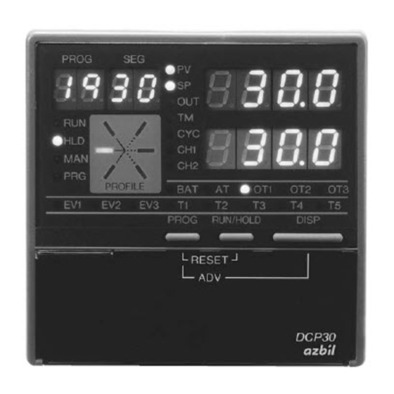
Chapter 2. NAMES & FUNCTIONS OF PARTS 2 - 2 Console The console comprises keys for operating the controller, displays and LEDs. ■ Basic display state The “basic display state” is the state in which the controller operat- ing state is displayed on the console. When the power is turned ON, the controller is in this state. Key operation changes the controller from the basic display state to one of the parameter setup, program setup, program copy or general reset states. Key operation also returns the controller to the basic display state. Power ON Parameter setups Program setups Basic display states Program copy General reset ■ Display Segment No. display Program No. -
Page 27: Basic Display State
Chapter 2. NAMES & FUNCTIONS OF PARTS • Segment No. display In the basic display state, this display indicates the currently selected segment No. In the program setup state, this display indicates the segment No. currently being set up. During constant-value operation, this display goes out in the basic display state. In the parameter setup state, this display indicates the item No. When an alarm occurs in the basic display state, the alarm code No. is displayed. • Mode indicator LEDs RUN, HLD: D isplay the READY, RUN, HOLD, FAST and END modes. (See following table.) Mode READY HOLD FAST Blinking Blinking MAN : L ights in the MANUAL mode, and goes out in the AUTO mode. PRG : L ights in the program setup state. Otherwise, this LED is out. • Upper display In the basic display state, displays PV and other values. - Page 28 Chapter 2. NAMES & FUNCTIONS OF PARTS OT2: W hen relay or voltage are assigned to output 2, lights when output is ON and goes out when output is OFF. In the case of 2G output models, lights when the closedside relay is ON and goes out when the relay is OFF. Lights when current output is assigned to output 2, and goes out when auxiliary output is assigned to output 2. OT3: Out • Basic indicator LEDs PV: Lights during PV display. Otherwise, this LED is out. SP: Lights during SP display. Otherwise, this LED is out. OUT: Lights during output display. Otherwise, this LED is out. TM: Lights during time display. Otherwise, this LED is out. CYC: Lights during cycle display. Otherwise, this LED is out. CH1: Out CH2: Out • Event LEDs EV1, EV2, : • In the basic display state or parameter setup state, light when each of events1 to 3 are ON, and go out when OFF.
- Page 29 Chapter 2. NAMES & FUNCTIONS OF PARTS ■ Keys DISP PROG : Program key : Display key FUNC : Function key : Left arrow key, right arrow key Loader jack : Up arrow key, down arrow key RUN/HOLD : Auto/Manual key : Run/Hold key : Auto-tuning key : Clear key...
-
Page 30: Keys
Chapter 2. NAMES & FUNCTIONS OF PARTS Category Function Key operation FUNC PARA Parameter setup Starts parameter setup. So the controller enters selection of setup group (major item). (in basic display state) PARA To change the setup group (major item) To fix the setup group To moves between individual items (minor items) To start changing individual item setting values... -
Page 31: Console
Chapter 2. NAMES & FUNCTIONS OF PARTS Category Function Key operation FUNC Program setup To clear item setting (while setting value is blinking) DISP To cancel changing item setting values (while setting value is blinking) FUNC To insert/delete segments FUNC PROG To change the program No. -
Page 32: Functions Using Two Or More Keys
Chapter 2. NAMES & FUNCTIONS OF PARTS ■ Functions using two or more keys PROG RUN/HOLD : R eset keys RUN/HOLD PROG P ress with held down in the basic display state to reset the controller. The controller enters the READY mode in the RUN, HOLD, FAST or END modes. The controller cannot be reset in the READY mode by key operation. PROG DISP : A dvance keys DISP PROG P ress with held down in the program operation mode in the basic display state to advance the program. -
Page 33: Loader Jack
Chapter 2. NAMES & FUNCTIONS OF PARTS FUNC DISP + + : G eneral reset keys DISP FUNC P ress and with held down in the READY AUTO mode in the basic display state to move to the general reset confirmation screen. ■ Loader jack This jack is for connecting the loader. Objects other than the loader plug should not be inserted into this jack. The loader jack is not isolated from internal digital circuits. Be sure to cap the loader jack when it is not in use. -
Page 34: Input Type And Range No.
Chapter 2. NAMES & FUNCTIONS OF PARTS 2 - 3 Input Type and Range No. ■ Inputs ● Thermocouple ● Input Format Range No. Code Temp. Range (°C) Temp. Range (°F) K (CA) 0 to 1200 0 to 2400 K (CA) 0.0 to 800.0 0 to 1600 K (CA) -
Page 35: Inputs
Chapter 2. NAMES & FUNCTIONS OF PARTS ● Resistance temperature detector (RTD) ● Input Format Range No. Code Temp. Range (°C) Temp. Range (°F) JIS' 89 Pt100 -200.0 to +500.0 -300 to +900 (IEC Pt100Ω) -200.0 to +200.0 -300 to +400 -100.0 to +150.0 -150.0 to +300.0 -50.0 to +200.0... - Page 36 Chapter 2. NAMES & FUNCTIONS OF PARTS Handling Precautions • The unit of code Z06 is Kelvin (K) • The lower limit readout of code B18 is 20 °C (68°F). The lower limit readout (°C) of codes K44, K46, T44, Z08 and Z07 is -199.9 °C.
-
Page 37: Chapter 3. Mounting
Chapter 3. MOUNTING 3 - 1 External Dimensions Unit: mm (18) 159.5 Mounting bracket 81405411-003 Soft dust-proof cover set (sold separately) 81446087-001 Hard dust-proof cover set (sold separately) 81446083-001 Terminal cover set (sold separately) 81446084-001 Terminal screw 78.4 Back plate Add-on terminal base... -
Page 38: Panel Cutout Dimensions
Chapter 3. MOUNTING 3 - 2 Panel Cutout Dimensions Use a steel panel of at least 2 mm in thickness for mounting the controller. Unit: mm Panel cutout dimensions Panel cutout dimensions during multiple mounted (recommended) + 0.8 96 x (N - 1) 96 x N - 4 N=number of units installed Panel cutout dimensions when mounting units horizontally and vertically (recommended) 99 min. -
Page 39: Mounting
3 - 3 Mounting WARNING Before removing, mounting, or wiring the DCP31, be sure to turn off the power to the DCP31 and all connected devices. Failure to do so might cause electric shock. Do not disassemble the DCP31. Doing so might cause electric shock. -
Page 40: Noise Generating Sources And Countermeasures
- P rovision of a CR filters for fast-rising noise Recommended CR filter: Azbil Corporation Model No. 81446365-001 - P rovision of a varister for noise with a high wave height Recommended varister: Azbil Corporation Model No. 8 1446366-001 (100 V) 81446367-001 (200 V) Handling Precautions • The varister may become short-circuited when trouble occurs. Pay attention to this when providing a varister on a controller. ■ Dust-proof cover Use the dust-proof cover when using the controller in a dusty or dirty location, and to prevent inadvertent operation. -
Page 41: Mounting Method
Chapter 3. MOUNTING ■ Mounting method Panel Mounting bracket 81405411-003 Mounting bracket • Firmly secure the top and bottom of the controller by the mount- ing brackets. • When mounting the controller, secure by lower mounting bracket (1) first. Mounting bracket Panel Panel Handling Precautions • To secure the controller, tighten the screw on the mounting bracket (supplied) until there is no more play and then tighten a further full turn. - Page 42 Chapter 3. MOUNTING • Keep the mounting angle to within 10° from the horizontal at both the controller rear top and bottom. Lift up from rear by 10° max. Pull down from rear by 10° max.
-
Page 43: Chapter 4. Wiring
Do not allow lead clippings, chips or water to enter the DCP31 case. Doing so might cause fire or faulty operation. Inputs to the current input terminals ( ) and ( ) on the DCP31 should be within the current and voltage ranges listed in the specifications. - Page 44 1MΩ. If the input impedance is less than 1MΩ, the DCP31 may not be able to detect sensor disconnection. • When inputting the DCP31’s I/O (parallel connection in case of input) to an A/D converter or analog scanner, read data may fluctuate.
-
Page 45: Compensating Lead
Chapter 4. WIRING 4 - 2 Compensating Lead In the case of thermocouple input, connect the bare thermocouple lead to the terminal. If the thermocouple is located a long way from the DCP31 or the thermocouple is connected to a ter- minal, extend the connection using a compensating lead and then connect to the terminal. Use shielded compensating leads only. • For I/O other than thermocouples, use JCS4364 instrument cable or equivalent product. (This is generally referred to “twisted shielded cable for instruments.”) The following cables are recom- mended. Fujikura Ltd. 2-core IPEV-S-0.9 mm x 1P 3-core ITEV-S-0.9 mm x 1T Hitachi Metals Ltd. 2-core KPEV 0.9 mm x 1P 3-core KTEV-S-0.9 mm x 1T • Shielded, multi-core microphone cord (MVVS) can be used if there is little electromagnetic induction. -
Page 46: Terminal Connections
Unit: mm 3.7dia. Handling Precautions • When installing the DCP31 in locations subject to vibration or impact, be sure to use round crimped terminals to prevent the lead from coming loose from the terminal. • When wiring with crimped terminals, take care to prevent con- tact with adjacent terminals. -
Page 47: Layout Of Terminals And Recommended Lead Draw-Out Direction
Chapter 4. WIRING 4 - 4 Layout of Terminals and Recommended Lead Draw-out Direction Wiring is carried out on the standard terminal base or add-on terminal base. The following dia- gram shows the recommended draw-out directions for the leads on the standard terminal base: The lead draw-out directions are the same when using the add-on terminal base. Lead draw-out Lead draw-out direction direction Standard terminal base... -
Page 48: Connecting The Ground And Power Supply
■ Ground When it is difficult to ground shielded cable, prepare a separate ground terminal (earth bar). Ground type: 100 Ω max. Ground cable: 2 mm sq. min soft-copper wire (AWG14) Cable length: Max. 20 m DCP31 terminal GND terminal plate GND (100 min.) Shielded cable Handling Precautions Use only the FG terminal ( ) on the DCP31 for grounding. Do not ground across other terminals. -
Page 49: Wiring Of Standard And Add-On Terminal Base
Chapter 4. WIRING 4 - 6 Wiring of Standard and Add-on Terminal Base ■ Standard terminal layout 5G output Instrument 6D output power supply External switch input (RSW) OD output 5K output 2G output 3D output Auxiliary output 90 to 264 Vac RSW1 50/60 Hz RSW2... -
Page 50: Connecting Inputs (Analog Inputs)
4 - 7 Connecting Inputs (analog inputs) CAUTION Inputs to the current input terminals 31 and 33 on the DCP31 should be within the current range listed in the specifications. Failure to do so might cause fire or faulty operation. -
Page 51: Connecting Control Outputs (Outputs 1, 2)
4 - 8 Connecting control outputs (outputs 1, 2) WARNING Before removing, mounting, or wiring the DCP31, be sure to turn off the power to the DCP31 and all connected devices. Failure to do so might cause electric shock. ■ Relay output (0D) -
Page 52: Position-Proportional Output (2G)
Chapter 4. WIRING ■ Position-proportional output (2G) Connect as follows paying attention to the switching direction: Open side Contact rating Load 4A (120 Vac, cosø=0.4) Power supply 2A (240 Vac, cosø=0.4) Load Closed side Open Feedback resistance 100 to 2500 Closed Handling Precautions • The life of internal relays is limited. Avoid setting the PID constant in such a way that results in exces- sive repeated ON/OFF switching. -
Page 53: Heat/Cool Output (3D)
Chapter 4. WIRING ■ Heat/cool output (3D) Connect as follows. Output 1 Load Contact rating, resistive load 5A (30 Vdc/120 Vac) Power supply 4A (240 Vac) Minimum switching current: 100 mA Output 2 Load Contact rating, resistive load 5A (30 Vdc/120 Vac) Power supply 4A (240 Vac) Minimum switching current: 100 mA... -
Page 54: Connecting Auxiliary Outputs (Outputs 2, 3)
Connecting auxiliary outputs (outputs 2, 3) Optional auxiliary outputs can be added on. WARNING Before removing, mounting, or wiring the DCP31, be sure to turn off the power to the DCP31 and all connected devices. Failure to do so might cause electric shock. ■ 0D, 5G, 6D auxiliary outputs... -
Page 55: Connecting Event Output (Relay Output)
Chapter 4. WIRING 4 - 10 Connecting Event Output (relay output) Event outputs EV1 and EV2 are 1a contact, and event output EV3 is 1a1b. Event outputs are con- nected on the standard terminal base. Standard terminal base Contact rating, resistive load EV1 1a Load 1A (30/250 Vdc) Power supply Contact rating, resistive load Load EV2 1a 1A (30/250 Vdc) Power supply Contact rating, resistive load Load EV3 1a1b... -
Page 56: Connecting Time Event Output (Open-Collector)
DCP31. Doing so will cause faulty open-collector output. (The DCP31 does not contain a short-circuit prevention circuit.) • When connecting to a semiconductor load such as a program- mable controller (sequencer), select a module whose current directions are matching. -
Page 57: Connecting External Switch (Rsw) Input
RSW12 Contact Handling Precautions • The external switch inputs on the DCP31 have built-in power supplies (open voltage 12 Vdc). Be sure to use no-voltage con- tacts for external contacts. • Use no-voltage contacts such as gold contacts whose small cur- rent can be switched ON/OFF. - Page 58 Chapter 4. WIRING ● Internal circuit for controller components for connecting external switch ● inputs Standard terminal base Add-on terminal base 12 Vdc 12 Vdc 12 Vdc 12 Vdc External External switch switch input input Internal circuit Internal circuit Handling Precautions • Do not connect to the SDC20/21 or SDC30/31 series in paral- lel.
-
Page 59: Connecting For Communications
Connecting for Communications Some controller models support the RS-485 communications interface. Select the RS-485 com- munications models by selected the required catalog No. Connect as follows. Handling Precautions The DCP31 operates as a slave station. ■ RS-485 interface Add-on terminal base Handling Precautions • Multi-drop connection of slave stations is possible. • Make sure that different addresses are set for each slave station. - Page 60 Chapter 4. WIRING ● 5-lead RS-485 mutual connection ● Terminating resistor Slave station DCP31 Terminating resistor Shielded cable Master station Slave station DCP31 Shielded cable Handling Precautions • Be sure to connect SG termi- nals each other. Failure to do so might cause unstable communications.
- Page 61 DIGITRONIK controller) Shielded cable Handling Precautions • Be sure to connect SG terminals each other. Failure to do so might cause unstable communications. Shielded cable Slave station (controller or DIGITRONIK controller) Terminating resistor Provide terminating resistors of 150 Ω ±5 %, 1/2 W min. at both ends of the communications path. Grounding of the shielded FG terminal should be carried out at only one end and not both ends. In this connection, the Azbil Corporation CMC10L001A000 can be used as a host sta- tion converter. When there are only three RS-485 terminals, terminals marked * are wired internally. 4-19...
-
Page 62: Isolating Inputs And Outputs
Chapter 4. WIRING 4 - 14 Isolating Inputs and Outputs The following figures show isolation between inputs and outputs. Solid lines show isolated items, and dotted lines show non-isolated items: ■ Control outputs 0D, 5G, 6D, 3D, 5K Input 1 Output 1 (full multiple-input PV (relay, current, voltage output) supported) Output 2 (relay, current, voltage output,... -
Page 63: Control Output 2G
Chapter 4. WIRING ■ Control output 2G Input 1 Output 1 (full multiple-input PV (control output 1a relay x 2) supported) Motor feedback input Output 3 (auxiliary output) Loader communications Loader jack Event output 1 (relay output 1a) 12 external switch inputs Event output 2 (relay output 1a) Event output 3... -
Page 65: Chapter 5. Functions
Chapter 5. FUNCTIONS 5 - 1 Data ■ Data types The DCP31 supports the following data types: For further details, see “Chapter 7. PARAMETER SETUP” and “Chapter 8. PRO- GRAM SETUP”. Data that can be changed even in Data Parameters Variable parameters RUN mode Event con guration data Data (e.g. event type) -
Page 66: Program Patterns
Chapter 5. FUNCTIONS 5 - 2 Program Patterns ■ Patterns SP and time comprise the settings for a single segment in a pattern. Up to 30 segments can be linked to create a broken-line whose verti- cal axis is SP and horizontal axis is time. This system is called the “RAMP-X” system. SP setting: Within range of SP limitter upper and lower limits Timesetting: 0 to 99 h, 59 min or 0 to 99 min, 59s (Select the time unit in setup data C 6 4.) SP is the point that corresponds to the time elapsed in the current segment on a straight line made by jointing the start point (SP set- ting value of the previous segment) to an end point (SP setting value of the current segment). Accordingly, segments are categorized as follows: • R ising ramp (rising ramp, rising tendency) Previous segment SP setting value < current segment SP setting value • F alling ramp (falling ramp, falling tendency) Previous segment SP setting value > current segment SP setting value • S oak (soak) Previous segment SP setting value = current segment SP setting value In the case of the No.1 segment, both the start and end points be-... - Page 67 Chapter 5. FUNCTIONS ■ Events 1 to 3, Time events 1 to 5 In event configuration data setup, they are used after setting the event type, event standby, hysteresis and ON delay time. A total of four event types which are PV type events, controller status events, time events and segment number events are available. Segment number events can be set by time events 1 to 5 only. In the constant-value operation mode, the time events 1 to 5 do not function. ● PV type events ● • B asic specifications T he next page shows event type PV, deviation, absolute value deviation, SP, MV and MFB. In the figures, the thick lines show ON-OFF changes in state. The upper line expresses the ON state, and the lower line the OFF state. E V and H stand for event setting value and hysteresis, respec- tively. Output in the READY state is OFF. • Event standby E vents function as follows when event standby has been set to ON: - I f the controller is in the state in the figure when changing from the READY to the RUN mode and after restoring the...
- Page 68 Chapter 5. FUNCTIONS • Segment progression - O utput is OFF until the program progresses to the segment containing the event setting. - W hen the program progresses to the segment containing the event setting, event ON/OFF operation is carried out according to the event setting value. - T he previous setting is valid until the program progresses to a segment containing a new event setting. F or this reason, set as follows to disable the event set in the previous segment from a certain segment onwards: Direct action events: Upper limit value of event setting Reverse action events: Lower limit value of event setting N ote, however, that some types of event turn ON even if events are set as shown above. - W hen the program has progressed to the No.1 segment by the cycle or pattern link functions, the previous setting is disabled. Output is OFF unless the No.1 segment contains an event setting. • Other O n 5G output models, when setup data C 1 8 is set to 1, and SP output (programmer functions) is selected, the MV direct/reverse event does not function.
- Page 69 Chapter 5. FUNCTIONS PV reverse Deviation direct Deviation reverse SP+EV SP+EV Absolute value deviation direct Absolute value deviation reverse SP direct SP reverse MV direct MV reverse MFB direct MFB reverse...
- Page 70 ● Controller status events ● Controller status events are turned ON and OFF according to the controller mode, alarm status and other statuses. Though the event standby function does not function, the ON delay function does. Event setting values (operating point), hysteresis and event standby are not set. • Basic operations The following basic operation types are provided: RUN+HOLD+FAST+END READY HOLD FAST G.Soak standby MANUAL Auto-tuning executing Constant-value operation MFB estimated position control, sum of all alarms PV range alarm Controller alarms Low battery voltage Console setup in progress Loader setup in progress Program end W hen the DCP31 reaches the state designated by the event type, the event is turned ON. Otherwise, the event is OFF. • Alarms A larms are divided into PV range alarm groups (alarm code Nos. 01 to 16) and controller alarm groups (alarm code Nos. 70 to 99, and low battery voltage). W hen the event type is set to the sum of all alarms, the event turns ON if any one of the alarms occurs.
- Page 71 Chapter 5. FUNCTIONS W hen the event type is set to PV range alarm, the event turns ON if any one of the alarms in the PV range alarm group occurs. W hen the event type is set to controller alarm, the event turns ON if any one of the alarms in the controller alarm group occurs. • ADV T his is ON for 1s after executing program advance. The event ON delay is disabled and a delay is not applied. • Program end W hen the DCP31 automatically (including ADV) reaches the READY mode from program operation status (RUN, HOLD, FAST) without performing RESET operation, the event is turned ON. When shifting from END mode to READY mode, the event is not turned ON as RESET operation is required. T his event is cancelled (ON→OFF) when one of the following conditions is satisfied: • When RESET operation is performed. • When shifting from READY to RUN mode. • When power is again supplied.
- Page 72 Chapter 5. FUNCTIONS ● Time events ● When the event 1 to 3 type is set to time event, the event can be used in the same way as time events 1 to 5. However, note that events 1 to 3 do not have segment No. event functions. Though the event standby function does not function, the ON delay function does. The ON and OFF times or only the ON time can be set for each event No. and segment. The following describes ON/OFF of output: • When the ON time is smaller than the Segment OFF time, output is ON for the duration ON time from the ON time to the OFF time. ON < OFF (See segments 1, 6 and 7 in the figure.) OFF time • When only the ON time is set, output is Output ON ON for the during from the ON time to Output OFF the segment end point. (See segments 2 and 5 in the figure.) Segment • When both the ON time and OFF time ON time are not set, output is OFF.
- Page 73 Chapter 5. FUNCTIONS However, ON and OFF times set for seg- Segment ment end points when the END mode is ON time shifted to are valid. ON = 0 (See segment 9 in the figure, and com- OFF time pare with segment 10 in the END mode.) Output ON • When the ON time is set to 0 (no OFF Output OFF continued time setting, or OFF time is greater than 0), output becomes OFF at time 0. Segment If output at the previous segment end G.Soak standby ON time point was ON at this time, the output OFF time status at the segment switching point Output ON does not momentarily become OFF. Segment time start (See segments 5 and 6 in the figure.) Output OFF • The G.Soak standby time is not included...
- Page 74 Chapter 5. FUNCTIONS ● Segment No. events ● The current segment No. is output as binary code. When all of T1 to T5 are selected as segment No. events in the time event type setup, all ON-OFF operations are as shown in the follow- ing table. When T1 to T4 are assigned in part to segment No. events, only the assigned time events operate as shown in the following table, and the remaining events operate as regular time events. Segment Event No. ON OFF ON OFF ON OFF ON OFF ON OFF ON OFF ON OFF ON OFF ON ON OFF OFF ON ON OFF OFF ON ON OFF OFF ON ON OFF OFF OFF ON ON ON ON OFF OFF OFF OFF ON ON ON ON OFF OFF OFF OFF OFF OFF OFF ON ON ON ON ON ON ON ON OFF OFF OFF OFF OFF OFF OFF OFF OFF OFF OFF OFF OFF OFF OFF...
-
Page 75: Pid Set Selection
Chapter 5. FUNCTIONS ■ PID set selection • Eight sets of PID parameters, PID1 to PID8, are used for control operation. When the PID set No. is set to each segment by designating the PID set segment, control output is calculated by each of the PID parameters. • There are two ways of selecting PID sets: by des- ignating the PID set segment and PID set auto- PID set No. switching. The method can be selected by setting PID set segment designation setup data C 1 1. C 1 1 set to 0: Designation of PID set segment C 1 1 set to 1: PID set auto-switching These two methods cannot be set simultaneously. Zone 8 CP. 1 7 Note Zone 7 When setup data C 1 1 is set to 1, PID items in CP. 1 6 Zone 6 the program setup are not displayed. -
Page 76: G.soak (Guarantee Soak)
Chapter 5. FUNCTIONS ■ G.Soak (guarantee soak) G.Soak ON/OFF and G.Soak width can be set for each segment. The G.Soak time can also be set by the variable parameter G S . t item. The G.Soak function ensures a segment execu- G.Soak width tion time with PV close to SP. G.Soak functions not only in soak segments but also in ramp G.Soak width segments. Segment set time At the segment start point, PV and SP are Segment execution time compared, and the absolute value of the result- ing deviation continues for the G.Soak time or G.Soak standby time Time count start Time longer. When the absolute value is smaller than G.Soak at segment start point the G.Soak width, operation of that segment is started. -
Page 77: Pv Start
Chapter 5. FUNCTIONS ■ PV start If PV start is set in the program setup, PV is SP pattern started by regular RUN operation. The first point where PV matches the SP in the Current program pattern (including bias for both PV Start point PV value and SP) is searched for, and operation is started from that point. Start point Start point However, note that if a matching point is not (1)' found, operation is started from the beginning of segment 1. (1)" When PV has started, event operating points and the time of time events are automatically PV start points corrected. If the PV start function is selected (1) PV starts at point A where the PV value first by setup data C 5 2 to C 5 4 settings relating to crosses the SP pattern. -
Page 78: Pattern Link
Chapter 5. FUNCTIONS ■ Pattern link “pattern link” is a function for linking pat- Program No.2 pattern-linked to program No.1 terns together. The link destination program No. is set by the Program No.1 pattern link item. When the pattern link item is set to 0 (initial setting), patterns are not linked. When the Time No. of the current program itself is set to the pattern link item, this creates an endless loop. If the SPs at the link source end point and the link destination start point do not match, the Program No.2 SP changes in a stepped manner during link operation. When cycle operation has been set, the pat- Time tern link function works after cycle operation has ended. After pattern link operation ends, operation begins from the No.1 segment of the link destination pattern, so operation is restarted with the settings of events 1 to 3 and time events 1 to 5 cleared. If PV start is programmed to the link destina- Time tion pattern, the PV start function operates Program No.1 Program No.2 after the link is made. -
Page 79: Mode
Chapter 5. FUNCTIONS 5 - 3 Modes ■ Mode types The following modes are available on the DCP31: Mode Program operation READY AUTO MANUAL AUTO MANUAL HOLD AUTO MANUAL FAST AUTO MANUAL AUTO MANUAL READY Constant-value operation AUTO MANUAL AUTO MANUAL ● Program operation ● Operation is carried out according to SP, times, events, etc. set to program patterns No.1 to 19. - Page 80 Chapter 5. FUNCTIONS ● READY ● In this mode, the DCP31 is ready for operation. MV output is fixed, and events to be operated according to event setting values turn OFF. However, events to be operated according to controller states are active. Parameters for all of the setup data, some event configuration data and some constantvalue operation data can be set or changed in the READY mode. During program operation, program pattern Nos.1 to 19 can be selected. ● RUN ● In this mode, the program is running. MV outputs are active in PID control or ON-OFF control, and events and time events are active. In the program operation mode, program operation progresses ac- cording to the elapsed time. However, note that progress of program operation stops in the same way as the HOLD mode when the controller is in the G.Soak (Guar- antee Soak) standby state. ● HOLD ● In this mode, the program is held. Progress of program operation stops. However, note that MV outputs are active in PID control or ON-OFF control, and events and time events are active in the same way as in the RUN mode. The HOLD mode is not available during constant-value operation. ● FAST ● In this mode, the program is fast-forwarded. This mode is like the RUN mode except that progress of the pro- gram operation time is speeded up. The time scale is selected by the variable parameter F A S T setting.
- Page 81 Chapter 5. FUNCTIONS ● END ● In this mode, operation of the program has ended. MV outputs are active in PID control or ON-OFF control, and events and time events are active with program operation stopped at the program end point. The END mode is not available during constant-value operation. ● AUTO ● In this mode, program operation is automatic. MV output is active according to controller control. (However, note that when programmer functions are selected on 5G output models, SP output is active according to controller control.) ● MANUAL ● In this mode, program operation is manual. MV output can be changed by , , , on the console or communications. (However, note that when programmer functions are selected on 5G output models, SP output can be changed by , , , on the console or communications.) 5-17...
-
Page 82: Mode Transition
Chapter 5. FUNCTIONS ■ Mode transition ● During program operation ● The solid lines in the below diagram show mode transition opera- tions. The broken lines show end of operation. RESET RESET HOLD END AUTO READY AUTO RUN AUTO HOLD AUTO END MANUAL READY MANUAL RESET RUN MANUAL HOLD MANUAL FAST FAST HOLD FAST AUTO FAST MANUAL RESET Mode changes to READY or END at end of operation. -
Page 83: Mode Transition Operations
Chapter 5. FUNCTIONS ■ Mode transition operations The following describes mode transition operations: Though “program end” is not an operation, it is described below as it is a factor in mode transition. ● RUN ● This operation involves shifting to the RUN mode from the READY, HOLD or FAST modes. To shift from the READY mode to the RUN mode, the DCP31 must be in the basic display state even in key, external switch input or communication operations. ● HOLD ● This operation involves shifting to the HOLD mode from the RUN or FAST modes. The HOLD mode is not available in the constant-value operation mode. ● RESET ● This operation involves shifting to the READY mode from the RUN, HOLD, FAST or END modes. In the program operation mode, this mode includes returning to the No.1 segment. ● ADV ● This operation involves advancing one segment in the READY, RUN, HOLD or FAST modes. The ADV mode is not available in the constant-value operation mode. ● FAST ●... - Page 84 Chapter 5. FUNCTIONS ● MANUAL ● This operation involves shifting to the MANUAL mode from the AUTO mode. When the DCP31 enters the MANUAL mode, the basic display state changes as follows. - When controller functions are selected, PV and output value (%) are displayed. - When programmer functions are selected, PV and SP are displayed. When the DCP31 enters the MANUAL mode from the AUTO mode by external switch inputs or communications, the display changes to the basic display state even in the parameter setup or program setup states. ● Program end ● When operation progresses in the RUN or FAST modes in the program operation mode, or when the segment has been advanced in the ADV mode, the program ends when all end points in the pro- gram setup including cycles and pattern links have been reached. You can select in the setup setting in which of the READY or END modes program operation ends. The program does not end in the constant-value operation mode. 5-20...
-
Page 85: Mode Transition Limitations
Chapter 5. FUNCTIONS ■ Mode transition limitations Mode transition can be carried out operating the console keys, external switching input and communications. The following table shows which operations are enabled in each of the modes: Operation HOLD RESET ADV * FAST (to RUN mode) (to HOLD mode) (to READY mode) (to next segment mode) (to FAST mode) Key Switch Com- Key Switch Com- Key Switch Com- Key Switch Com- Key Switch Com- muni-... -
Page 86: Controller And Programmer
The DCP31 is limited to use as a controller at all times on other models. ● Controller ● When the DCP31 is used as a controller, PID control operation is carried out according to PV, SP AND PID setting values, and the resulting manipulated variable (MV) is output as an analog output. ON-OFF control, heat/cool PID control and 3-position-proportional is also possible depending on the type of output supported by the model of DCP31. In the MANUAL mode, the MV can be incremented or decrement- ed in the basic display state by the console keys. DCP31 controller Controlled system ● Programmer ● When the DCP31 is used as a programmer, PID control operation is not carried out, and the SP is output in the scaled 4 to 20mA range. In the MANUAL mode, the SP can be incremented or decremented in the basic display state by the console keys. DCP31 programmer SP output 4 to 20mA RSP input SDC series SDC series SDC series... -
Page 87: Input Processing Functions
Chapter 5. FUNCTIONS 5 - 5 Input Processing Functions Input processing is carried out in the order shown below. Analog input 1 Setting: Setup data C03 Input range type A/D conversion (resistance temperature detector) Wiring resistance compensation (thermocouple) Cold junction compensation Setting: Setup data C 7 2 (DC current and voltage) Square-root extraction Setting: Setup data C0 7 (DC current and voltage) -
Page 88: Output Processing Functions
Chapter 5. FUNCTIONS 5 - 6 Output Processing Functions Three outputs are provided as output processing functions: control output, SP output and aux- iliary output. ■ Control output When the DCP31 is selected for use as a controller, control output is operational. How outputs are processed varies according to the output type supported on the model. ● 5G output ● Initialization of PID control Setting: Variable parameters 1 OUT/rpi d operation Setting: PID parameters p/ 1 / d/8 E... - Page 89 Preset manual value Setting: Setup data C 14/C 15 Handling Precautions Manual MV In ON-OFF control, the DCP31 cannot be MANUAL mode set to the MANUAL mode. (The DCP31 can be set to the MANUAL mode as ON-OFF control is not possible in the READY mode.)
- Page 90 Chapter 5. FUNCTIONS ● 2G output ● Initialization of PID control operation Setting: Variable parameters 1 OUT/rpi d Setting: PID parameters p/ 1 / d/RE PID control operation PID parameters dP/di /dd PID parameters br Output change limitter Setting: Variable parameters OTL Setting: Variable parameter AT AT operation AT execution...
- Page 91 READY mode Preset manual value Setting: Setup data C 14/C 15 Handling Precautions Manual MV In 3-position control, the DCP31 cannot MANUAL mode be set to the MANUAL mode Manipulated variable (MV1) Setting: Variable parameter DI FF Heat-cool MV operation...
-
Page 92: Sp Output
Chapter 5. FUNCTIONS ■ SP output When the DCP31 is selected for use as a programmer, control output is operational. On 5G output models, SP output is processed is as follows: Main output types Setting: Setup data C 18 Setting: Setup data C 19/C20 Upper/lower limit scaling Setting: Setup data C 16 MV in READY mode READY mode Manual SP1 Upper/lower limit scaling... -
Page 93: Auxiliary Output
Chapter 5. FUNCTIONS ■ Auxiliary output ● Auxiliary output 1 ● When auxiliary output 1 or 2 are supported on 0D, 5G or 6D output models, auxiliary output 1 is processed as follows: Auxiliary output 1 type Setting: Setup data C46 Upper/lower limit scaling Setting: Setup data C47/C48 When READY mode is entered at auxiliary 4 mA (0 mA) output type SP and deviation When auxiliary output type is NOP When auxiliary output type is set to MFB on non-2G output models... -
Page 95: Chapter 6. Operation
Chapter 6. OPERATION 6 - 1 Turning the Power ON The DCP31 is not equipped with a power switch or protective fuses. If necessary, prepare these externally. When a voltage of 90 to 264 V ac is applied across terminals and on the DCP31, display appears for about 10 s after which control and other operations are started. During controller startup until start of operations, the LEDs on the profile display light successively at uneven in- tervals clockwise from top right. The following diagram shows the flow of operations at startup: ● Startup flow ● Power ON RAM backup normal? Check start of general reset Press key. Continuation of program operation/constant-value operation Parameter=factory shipment setting modes Delete entire program. -
Page 96: Switching The Basic Display
Chapter 6. OPERATION 6 - 2 Switching the Basic Display The “basic display state” of the controller collectively refers to the display state of the program No. display, segment No. display, upper display, lower display, basic indicator LED lamps and event LEDs. DISP Each press of successively switches the basic display state. Operation of other displays and LEDs is carried out in the same way even when setting up parameters, for example. However, DISP switching by is not possible. The following figure shows the conventions used for displays in this manual. Program/segment No. Display In the program operation mode, READY indicates the currently selected program/segment No. Displays other than READY indicate the currently operating program/segment No. -
Page 97: Display In Program Operation Mode
Chapter 6. OPERATION ■ Display in program operation mode functions DISP ● ● Output Model No. Display Display 1 → Display 2 → Display 5 → Display 6 → 0D, 5G, 6D Display 7 → Display 1 (repeated) Display 1 → Display 2 → Display 3 → Display 5 → Display 6 →... - Page 98 Chapter 6. OPERATION ● Display 3 ● Program No. Segment No. Pattern Motor valve opening (%) tendency Output states of events 1 to 3, time events 1 to 5 This display is exclusive to 2 G output models (output catalog No. appended with 2 G). ● Display 4 ● Program No. Segment No. Heat-side output (%) Pattern Cool-side output (%) tendency...
- Page 99 Chapter 6. OPERATION ● Display 6 ● Program No. Segment No. Pattern Number of remaining cycles tendency Output states of events 1 to 3, time events 1 to 5 When the remaining number of cycles is “0”, subsequent cycle operation is not carried out. ● Display 7 ● Program No. Segment No. Pattern Time tendency Output states of events 1 to 3, time events 1 to 5...
-
Page 100: Display In Constant-Value Operation Mode
Chapter 6. OPERATION ■ Display in constant-value operation mode DISP functions ● ● Output Display Model No. Display 1 → Display 2 → Display 1 (repeated) 0D, 5G, 6D Display 1 → Display 2 → Display 3 → Display 1 (repeated) Display 1 →... - Page 101 Chapter 6. OPERATION ● Display 3 ● Motor valve opening (%) Output state of events 1 to 3 This display is exclusive to 2 G output models (output catalog No. appended with 2 G). ● Display 4 ● Heat-side output (%) Cool-side output (%) Output state of events 1 to 3 This display is exclusive to heat/cool output models (output catalog No. appended with 3 D or 5 K).
-
Page 102: Program Selection
Chapter 6. OPERATION 6 - 3 Program Selection The program No. can be selected on the console within the range 1 to 19. ■ How to select the program No. When the controller is in the basic display state in the program Program No.1 operation READY mode: PROG • Each press of increments PROG the program No. The display Program No.2 reverts to 1 after 19. • Each press of decrements PROG the program No. The display reverts to 19 after 1. Program No.3 Program No.4 PROG Handling Precautions • Both already set or non-set program Nos. -
Page 103: External Switch (Rsw) Operations
Chapter 6. OPERATION 6 - 4 External Switch (RSW) Operations ■ External switch (RSW) inputs In all, the DCP31 is provided with 12 external switch inputs. Each of these inputs are differentiated by RSW1, RSW2 and so forth to RSW12. On models whose option 2 catalog No. is “0”, only inputs RSW1 to RSW4 are mounted. (RSW: external switch input) ● External switch input types ● The functions of RSW1 to 4, and RSW8 to 12 are fixed. The functions of RSW5 to 7 are selected by the setup setting. Function External Detection Method Switch No. RSW1 Rising edge RSW2 HOLD Rising edge... - Page 104 Chapter 6. OPERATION • With G.Soak cancel by OR conditions, G.Soak standby is can- celed when the external switch turns ON or when the PV enters the G.Soak width. • With G.Soak cancel by AND conditions, G.Soak standby is can- celed when the external switch turns ON or when the PV enters the G.Soak width. • When the external switch turns ON by direct/reverse action switching, control operation is the opposite to that set in setup parameter C 0 1 . When the external switch turned OFF, control operation is that set in setup parameter C 0 1 . 6-10...
-
Page 105: Program Selection
Chapter 6. OPERATION ■ Program selection The program can be selected in the program operation READY mode. The table below shows program selection by external switch inputs. Two external switch states are provided for selection of pro- grams 10 to 15. When program selection by external switch inputs is set to “0”, the program can be selected by the console keys and by communication with a personal computer. External Weighting State Switch No. RSW8 OFF ON OFF ON OFF ON OFF ON OFF ON RSW9 OFF OFF ON ON OFF OFF ON ON OFF OFF RSW10 OFF OFF OFF OFF ON ON ON ON OFF OFF RSW11 OFF OFF OFF OFF OFF OFF OFF OFF ON ON... -
Page 106: Read Timing
Chapter 6. OPERATION ■ Read timing ● Timing of RSW1 to 7 ● Inputs RSW1 to RSW7 are read according to the following timing. (1) W hen input changes state from OFF to ON, the time from the change up to reading is 0.2 s max. (2) W hen input changes state from ON to OFF, the time from the change up to reading is 0.2 s max. ON read OFF read External switch input state ● Timing of RSW8 to 12, RUN and PV start ●... - Page 107 Chapter 6. OPERATION Program selection No. State of No. di erent State of State of No. di erent (5 inputs) from that selected selected No. from that selected RUN signal Program No. No. di erent from that selected Selected No. Mode READY Handling Precautions...
-
Page 108: Manual Operation And Auto-Tuning
Chapter 6. OPERATION 6 - 5 Manual Operation and Auto-tuning ■ Manual operation In the MANUAL mode, controller outputs can be manipulated by or on the console. ● Controller functions ● When outputs are displayed in the basic display state, only one digit in the output value blinks. If the output value is incremented or decremented by or , actual output also increments or decrements. Output values differ from values being entered to setting items in that need not be pressed. The blinking digit can be moved by pressing or On 2G output models, when only estimated position-proportional control is selected by variable parameter .-C setting 2, “—” not the value is displayed as the output display in the MANUAL mode. Pressing displays “O p e n” , and the open-side relay turns ON. Pressing displays “C l O S” , and the closed-side relay turns ON. Bump-less and preset output changes when shifting from the AUTO to the MANUAL mode can be selected by setup parameter C 15 set- ting. When shifting from the MANUAL to the AUTO mode, output is bumpless. (However, when the total time for the PID parameter of the PID set in use is set to “0”, a sudden change in output occurs.) ●... -
Page 109: Auto-Tuning (At)
Chapter 6. OPERATION ■ Auto-tuning (AT) When operating in the AUTO mode in either of the RUN, HOLD, FAST or END modes, setting values can be automatically written to the PID set in use by auto-tuning (AT). The following can be selected by variable parameter A t setting. 0: AT is disabled. 1: General AT is executed. 2: Overshoot-inhibited AT is executed. 3: AT by neural net is executed. • Auto-tuning does not function when programmer functions are selected on 3D or 5K heat/cool output models and 5G output models. • During execution of auto-tuning, progress of program operation time stops. Accordingly, the controller is in a similar state to the HOLD mode even in the RUN or FAST modes. • Auto-tuning in all instances involves calculating the downtime and critical sensitivity of the line according to two limit cycles and PID values according to suitable characteristic equations for each, and automatically writing these PID values. • During execution of auto-tuning, PV fluctuates according to fluctuations in MV. Before executing auto-tuning, make sure that fluctuations in PV will not cause controller trouble. • Normally, suitable values are written by setting variable param- eter At setting to 1 or 3. However, when executing auto-tuning on a line that easily overshoots, either set to 2, or also use smart- tuning for carrying out overshoot inhibit control. Setting to 3 executes AT by neural net so that the suitable value is calculated for wider range applications. • The point at which output at auto-tuning is inverted (lower limit to upper limit, and vice versa) is determined as follows from SP and PV at start of auto-tuning. - Page 110 Chapter 6. OPERATION At start At SP=PV operation PV>SP PV<SP Time Time AT start Normal end AT start Normal end • Auto-tuning can be started by , external switch inputs and communications. During auto-tuning, the AT LED blinks. • If one or more of the following conditions occurs during auto- tuning, auto-tuning is canceled without PID constants being writ- ten, and the AT LED goes out. - Cancel by - Cancel by external switch input - Cancel by communications - Change in mode (shift to MANUAL mode or READY mode) - E xecution of automatic motor valve opening adjustment on 2G output models - When variable parameter A t setting is changed to “0” - When input 1 becomes out-of-range Handling Precautions • Auto-tuning will not function properly unless the control target is connected.
-
Page 111: Chapter 7. Parameter Setup
Chapter 7. PARAMETER SETUP 7 - 1 Parameter Setup Parameters can be set up when the DCP31 is in the basic display state. DISP If the DCP31 is not in the basic display state, press to set the controller to the basic display state. ■ Selecting the setting group in the parameter setup Parameter setup is divided into two stages: setting group (major item) and individual item (minor item). PARA FUNC If you press in the basic display state, the display chang- es to selection of setting group (major item), the setting group is displayed on the upper display, and the lower display goes out. PARA If you press or , the setting group display changes in order. Basic Display State DISP... -
Page 112: Moving Individual Items In The Parameter Setup
Chapter 7. PARAMETER SETUP Upper Name Remarks Display Variable P A R A parameters Event configu- This parameter is not displayed when variable parameter L O C is 2 or 4 ration data PID parameters This parameter is not displayed when variable parameter L O C is 2 or 4 P 1 D This parameter is not displayed when constant-value operation data .O D E is 1... -
Page 113: Changing Individual Items And How To Return From The Setup State
Chapter 7. PARAMETER SETUP ■ Changing individual items and how to return from the setup state If you press when an individual item is displayed, the setting value blinks. This state is referred to as the “setting value entry state.” In this state, pressing or can increment or decre- ment the setting value that is blinking. Also, pressing or moves the position of the digit that is blinking. If you press when the setting value is at the desired value, blinking stops, the display returns to its normally lit state, and the new setting value is stored to internal memory. PARA DISP PARA To cancel changing of setting values, press or . When is pressed, the value stops blinking and the display returns to its normal lit state. DISP If you press , the display returns to the basic display state. If “- - - -” is displayed at the lower display when an individual item is displayed, or the controller does not enter the setting value entry state by pressing... - Page 114 Chapter 7. PARAMETER SETUP DISP Basic Display State DISP key, Setting group selection Individual items Setting value key, (major items) (minor items) blinking PARA PARA key * key, Change setting value. Individual items (minor items) stores setting values to memory. PARA does not store setting values to memory.
-
Page 115: How To Register Functions To Keys
Chapter 7. PARAMETER SETUP 7 - 2 How to Use PARA PARA Use for calling up individual items in frequently changed parameters. ■ How to register functions to keys Up to eight individual items in the parameter setup can be assigned PARA to each key. The assignment item must be registered to use this feature. This feature allows you to call up individual items more easily in the following order: FUNC PARA → selection of setting group → individual item matrix. ● How to register assignment items ● To register an assignment item, add the following base correspond- ing to the setting group to the item No., and then set the resultant PARA value to setup data C 5 5 to C 6 2 ( assignment items 1 to 8):... - Page 116 Chapter 7. PARAMETER SETUP ● Example ● PARA PARA Let’s register four individual items to . If you press in the basic display state, the 1st to 4th individual items in the table below are displayed successively. In this example, let’s change the setting values. PARA Order Item to Call by Setup data C 0 1 PID parameter P -2 Variable parameter Variable parameter F A S T The settings for registering these individual items are as follows: Setup Data Setting “ S E t ” Item Code Setting [auxiliary...
- Page 117 Chapter 7. PARAMETER SETUP PARA ● Operations by ● PARA If you press in the basic display state, registered individual PARA items are called up. Each press of successively calls up (up to eight) registered individual items. Only individual items to which valid assignment settings have been registered can be called up. PARA operations are not limited by the setting of “variable parameter PARA setup” L O C (key lock) setting. operations are described on the following page: DISP DISP Display item by Display item by PARA Basic Display PARA PARA key assign- key assign- State ment item 1...
-
Page 118: Parameter Setup List
Chapter 7. PARAMETER SETUP 7 - 3 Parameter Setup List Note “U” and “%FS” used in the “Factory Setting” and “Setting” columns in the table mean the following: T he decimal point changes according to the input range type setting. For example, when one digit past the decimal point is allowed, -1999 U becomes 199.9, and 9999 U becomes 999.9. %FS: T he numbers and decimal point position changes according to the input range setting. F or example, when the input range is 0.0 to 800.0°C, 0 %FS is 0.0 and 100 %FS is 800.0. ■ Variable parameter settings “ P A R A ” Factory User No. Item Code Item Setting Setting... - Page 119 Chapter 7. PARAMETER SETUP Factory User No. Item Code Item Setting Setting Setting PID operation initial 0.0 to 100 % 1 O U T MV (CH1) (50.0) [Note] On heat/cool models, the factory set- ting is 50.0. PID operation 0: Automatic judgment of initialization is R P 1 D initialization carried out by advance operation.
- Page 120 Chapter 7. PARAMETER SETUP Factory User No. Item Code Item Setting Setting Setting 16 C P . 1 4 PID auto-switching 600 U -1999 to +9999 U point 1-4 [Note] On heat/cool models, “– – – –” is dis- 17 C P . 1 5 PID auto-switching 800 U played and setting is not possible.
- Page 121 Chapter 7. PARAMETER SETUP Factory User No. Item Code Item Setting Setting Setting 23 C Y . 2 Output 2 time 5 to 120 s (relay output) proportional output 1 to 60 s (voltage output) cycle [Note] On models whose output 2 is neither relay output nor voltage output, “–...
-
Page 122: Description Of Variable Parameter Settings
Chapter 7. PARAMETER SETUP Factory User No. Item Code Item Setting Setting Setting Motor valve open- 1000 0 to (fully open adjustment - 500) .-c l ing adjustment fully [Note] closed position On models other than 2G output mod- els, “– – – –” is displayed and setting is not possible. - Page 123 Chapter 7. PARAMETER SETUP • When L O C is set to 3, the following keys are disabled. PROG Basic display state: (program selection) (program selection) RUN/HOLD (RUN, HOLD) PROG RUN/HOLD (RESET) PROG DISP (ADV) FUNC (FAST) (AUTO, MANUAL) (AT start, AT cancel) FUNC DISP (general reset) However, note that MV (when controller functions are selected) and SP (when programmer functions are selected) can be changed in the basic display state in the MANUAL mode. • W hen L O C is set to 4, all keys disabled when L O C is set to 2 and 3 are disabled.
- Page 124 Chapter 7. PARAMETER SETUP ● I O U t (PID operation initial MV) ● PID operation is started in the following cases using the I O U t set- ting value: • W hen the mode changes from READY AUTO to RUN AUTO • W hen the power is turned ON in the RUN AUTO (or HOLD, FAST, END AUTO) mode • At completion of auto-tuning As the PV, SP and PID parameters settings bear a relation to PID operation, the first MV resulting from PID operation will not necessarily match the I O U t setting value. ● R P I D (PID operation initialization) ● When SP changes suddenly by ADV (advance) operation, rate ac- tion in PID operation may cause the MV in the operation to change excessively. For this reason, excessive changes can be suppressed by...
- Page 125 Chapter 7. PARAMETER SETUP • The AT LED lights while reviewing the B R value when set to 2. • D o not set to 2 when normal control is not being carried out due to inappropriate tuning of the PID constant, for example. Also, hunting is more likely to occur when B R is set to a large value on quick-starting lines. Set the B R value to 0 then to 2. • On heat/cool models, smart-tuning does not function. ● 2 P I D (2 degrees of freedom) ● 0: 2 degrees of freedom is disabled. 1: 2 degrees of freedom is enabled. • 2 degrees of freedom is a function for improving the response to disturbance during setup without losing conventional characteris- tics at rise (or fall). When set to 1, optimum PID constants can be set individually for inhibiting disturbance in addition to conventional the PID con- stant. These constants are set automatically during AT execution, and is memorized. They can also be set and changed independently.
- Page 126 Chapter 7. PARAMETER SETUP • Position-proportional control dead zone On 2G output models, a dead zone between the motor open and mo- tor closed positions is set. As a general guideline, the minimum value is the value where this dead zone changes to stop motor hunting once a fixed value set to manual output is being output. If this value is set without any margin, the motor will be operating at all times, which will considerably shorten its service life. The factory setting is 5 %. Use this as a guideline, and take the con- trol results and motor service life into consideration when setting the dead zone. *: Dead zone setting value Dead zone Closed-side Open-side relay ON relay ON Control output (%) MFB (%) • Heat-cool control dead zone -100 to +50 % Heat-cool control is calculated as follows: Note 4) PID set selection (1 of 4 sets) Heat-side Cool-side...
- Page 127 Chapter 7. PARAMETER SETUP Note 1) O n heat/cool models, this sets how the relationship between heat-side output and cool-side output should be processed with respect to the MV resulting from PID operation. Dead zone<0 Dead zone=0 100 % 100 % Dead zone Control output values Output Output Output Output (cool) (heat) (cool) (heat) 50 % 100 % 50 % 100 % Dead zone>0 100 % Dead...
- Page 128 Chapter 7. PARAMETER SETUP ● D v -L (3-position control deviation lower limit) ● ● D v -H (3-position control deviation upper limit) ● ● H Y -L (3-position control lower limit hysteresis) ● ● H Y -H (3-position control upper limit hysteresis) ●...
- Page 129 Chapter 7. PARAMETER SETUP .-C (motor control method selection) ● ● 0: MFB control (conventional) + estimated position control 1: MFB control (conventional) only 2: Estimated position control only • 0: MFB control (conventional) + estimated position control • W hen MFB (Motor Feed Back) input is normal, the motor position is controlled by the actually measured MFB. • W hen MFB input is in error, the motor position is controlled by an estimated MFB value. This state is referred to as “estimated posi- tion control state.” For example, when the motor rotates at a position where the feed- back potentiometer has deteriorated, MFB input changes suddenly. This sudden change is detected as an error, and the correct MFB position is estimated. The motor position is also controlled by the estimated MFB value when the MFB disconnected alarm has occurred. • I n the estimated position control state, an error will inevitably occur between the actual motor valve opening and estimated MFB value. So, set the closed-side relay to ON at all times when output (MV) ≤ 0.0 %, and the open-side relay to ON at all times when MV ≥...
- Page 130 Chapter 7. PARAMETER SETUP • The MFB disconnected alarm does not occur. • T he error between actual motor valve opening and estimated MFB value is compensated by forcibly continuing motor operation in the closed or open directions when MV is 0.0 % and 100 %. .-A t (motor valve opening automatic adjustment) ● ● 0: Adjustment disabled 1: Adjustment enabled This parameter automatically measures the motor fully closed position, fully open position, and close-open times. The results of calculation are automatically written to .-C L , .-O P and .-t . • Adjustment Method and Motor Functions 1. Set .-C to 0 or 1. 2. Set .-A t to 1, and press I f set to 1 already, press twice to enter automatic adjust- ment.
- Page 131 Chapter 7. PARAMETER SETUP matic re-adjustment has ended successfully or when the power has been reset. - Fully closed count - fully open count < 500 - Fully closed count > fully open count - Time from fully closed to fully open is less than 5 s - M FB disconnected alarm ( A L 1 0 , A L 1 1 ) occurs continu- ously or frequently - The time taken for the MFB count to stabilize exceeds 5 min - F aulty wiring of MFB or switching relay (However, note that all faulty wiring cannot be detected as an error.) .-t (motor valve opening adjustment fully open/closed time) ●...
-
Page 132: Event Configuration Data Settings " E V "
Chapter 7. PARAMETER SETUP ■ Event configuration data settings “E v” Factory User No. Item Code Item Setting Setting Setting Event 1 type PV type events E T 1 0: PV direct 1: PV reverse 2: Deviation direct 3: Deviation reverse 4: Absolute value deviation1 direct 5: Absolute value deviation1 reverse 6: SP direct... - Page 133 Chapter 7. PARAMETER SETUP Factory User No. Item Code Item Setting Setting Setting Event 1 standby 0: Standby OFF E D 1 1: Standby ON [Note] The controller stands by after power is restored and in the READY mode. When the event type setting is ≥ 50, “–...
- Page 134 Chapter 7. PARAMETER SETUP Factory User No. Item Code Item Setting Setting Setting Event 2 type PV type events E T 2 0: PV direct 1: PV reverse 2: Deviation direct 3: Deviation reverse 4: Absolute value deviation1 direct 5: Absolute value deviation1 reverse 6: SP direct 7: SP reverse 8: MV direct...
- Page 135 Chapter 7. PARAMETER SETUP Factory User No. Item Code Item Setting Setting Setting Event 2 standby 0: Standby OFF E D 2 1: Standby ON [Note] The controller stands by after power is restored and in the READY mode. When the event type setting is ≥ 50, “–...
- Page 136 Chapter 7. PARAMETER SETUP Factory User No. Item Code Item Setting Setting Setting Event 3 type PV type events E T 3 0: PV direct 1: PV reverse 2: Deviation direct 3: Deviation reverse 4: Absolute value deviation1 direct 5: Absolute value deviation1 reverse 6: SP direct 7: SP reverse 8: MV direct...
- Page 137 Chapter 7. PARAMETER SETUP Factory User No. Item Code Item Setting Setting Setting 10 E D 3 Event 3 standby 0: Standby OFF 1: Standby ON [Note] The controller stands by after power is restored and in the READY mode. When the event type setting is ≥...
- Page 138 Chapter 7. PARAMETER SETUP Factory User No. Item Code Item Setting Setting Setting 17 E t . t 1 T1 event type PV type events 0: PV direct 1: PV reverse 2: Deviation direct 3: Deviation reverse 4: Absolute value deviation1 direct 5: Absolute value deviation1 reverse 6: SP direct 7: SP reverse...
- Page 139 Chapter 7. PARAMETER SETUP Factory User No. Item Code Item Setting Setting Setting 18 E d . t 1 T1 event standby 0: Standby OFF 1: Standby ON [Note] The controller stands by after power is restored and in the READY mode. When the event type setting is ≥...
- Page 140 Chapter 7. PARAMETER SETUP Factory User No. Item Code Item Setting Setting Setting 21 E t . t 2 T2 event type PV type events 0: PV direct 1: PV reverse 2: Deviation direct 3: Deviation reverse 4: Absolute value deviation1 direct 5: Absolute value deviation1 reverse 6: SP direct 7: SP reverse...
- Page 141 Chapter 7. PARAMETER SETUP Factory User No. Item Code Item Setting Setting Setting 22 E d . t 2 T2 event standby 0: Standby OFF 1: Standby ON [Note] The controller stands by after power is restored and in the READY mode. When the event type setting is ≥...
- Page 142 Chapter 7. PARAMETER SETUP Factory User No. Item Code Item Setting Setting Setting 25 E t . t 3 T3 event type PV type events 0: PV direct 1: PV reverse 2: Deviation direct 3: Deviation reverse 4: Absolute value deviation1 direct 5: Absolute value deviation1 reverse 6: SP direct 7: SP reverse...
- Page 143 Chapter 7. PARAMETER SETUP Factory User No. Item Code Item Setting Setting Setting 26 E d . t 3 T3 event standby 0: Standby OFF 1: Standby ON [Note] The controller stands by after power is restored and in the READY mode. When the event type setting is ≥...
- Page 144 Chapter 7. PARAMETER SETUP Factory User No. Item Code Item Setting Setting Setting 29 E t . t 4 T4 event type PV type events 0: PV direct 1: PV reverse 2: Deviation direct 3: Deviation reverse 4: Absolute value deviation1 direct 5: Absolute value deviation1 reverse 6: SP direct 7: SP reverse...
- Page 145 Chapter 7. PARAMETER SETUP Factory User No. Item Code Item Setting Setting Setting 30 E d . t 4 T4 event standby 0: Standby OFF 1: Standby ON [Note] The controller stands by after power is restored and in the READY mode. When the event type setting is ≥...
- Page 146 Chapter 7. PARAMETER SETUP Factory User No. Item Code Item Setting Setting Setting 33 E t . t 5 T5 event type PV type events 0: PV direct 1: PV reverse 2: Deviation direct 3: Deviation reverse 4: Absolute value deviation1 direct 5: Absolute value deviation1 reverse 6: SP direct 7: SP reverse...
- Page 147 Chapter 7. PARAMETER SETUP Factory User No. Item Code Item Setting Setting Setting 34 E d . t 5 T5 event standby 0: Standby OFF 1: Standby ON [Note] The controller stands by after power is restored and in the READY mode. When the event type setting is ≥...
-
Page 148: Description Of Event Configuration Data
Chapter 7. PARAMETER SETUP ■ Description of event configuration data ● E D 1 to 3 (event 1 to 3 standby) ● ● E D . t 1 to 5 (T1 to T5 event standby) ● 0: Standby OFF 1: Standby ON • W hen set to standby ON, event output becomes OFF if the con- troller is in the standby state even if the condition for turning event output ON is satisfied. -
Page 149: Pid Parameter Settings " P I D "
Chapter 7. PARAMETER SETUP ■ PID parameter settings “P I d” Factory User No. Item Code Item Setting Setting Setting Proportional band 100.0 : 0.0 to 999.9 % (0D, 6D output models) P -1 (PID set 1) 0.0 enables ON-OFF control. 0.1 to 999.9 % (models other than Reset time 1 -1... - Page 150 Chapter 7. PARAMETER SETUP Factory User No. Item Code Item Setting Setting Setting 18 D P -2 Disturbance inhibit 100.0 • O n heat/cool models, the set No. of the proportional band PID parameter used for the PID set No. (PID set 2) is as follows: 19 D I -2 Disturbance inhibit PID Set No.
- Page 151 Chapter 7. PARAMETER SETUP Factory User No. Item Code Item Setting Setting Setting 31 P -4 Proportional band 100.0 • I ncreasing the rate time ( D , D D ) allows (PID set 4) overshoot to be inhibited more easily. However, it also make hunting more 32 1 -4 Reset time likely to occur as the controller reacts...
- Page 152 Chapter 7. PARAMETER SETUP Factory User No. Item Code Item Setting Setting Setting 48 D P -5 Disturbance inhibit 100.0 proportional band (PID set 5) 49 D I -5 Disturbance inhibit reset time (PID set 5) 50 D D -5 Disturbance inhibit rate time (PID set 5)
- Page 153 Chapter 7. PARAMETER SETUP Factory User No. Item Code Item Setting Setting Setting 65 O H -7 MV upper limit 100.0 (PID set 7) 66 R E -7 Manual reset 50.0 (PID set 7) 67 B R -7 Brake (PID set 7) 68 D P -7 Disturbance inhibit 100.0...
-
Page 154: Setup Data Settings " S E T "
Chapter 7. PARAMETER SETUP ■ Setup data settings “S E t” Factory User No. Item Code Item Setting Setting Setting Control action (CH1) 0: Reverse action (heat) C 0 1 1: Direct action (cool) [Note] On heat/cool models, “– – – –” is dis- played and setting is not possible. - Page 155 Chapter 7. PARAMETER SETUP Factory User No. Item Code Item Setting Setting Setting Input 1 range lower Not fixed -1999 to +9999 U C 0 5 limit (0 %) [Note] When the input 1 range type is non- linear, “– – – –” is displayed and setting is not possible.
- Page 156 Chapter 7. PARAMETER SETUP Factory User No. Item Code Item Setting Setting Setting 11 C 1 1 PID set autoswitch- 0: OFF (PID set segment designation) ing (CH1) 1: ON [Note] When set to 1, the PID set items in the program are invalid.
- Page 157 Chapter 7. PARAMETER SETUP Factory User No. Item Code Item Setting Setting Setting 19 C 1 9 SP1 main output 0 U -1999 to +9999 U lower limit (4 mA set- [Note] ting) When the model is not a 5G output model and 8 setting is 0 on a 5G out- put model, “–...
- Page 158 Chapter 7. PARAMETER SETUP Factory User No. Item Code Item Setting Setting Setting 45 C 4 5 3-position control 0: 3-position control disabled 1: 3-position control enabled [Note] On models not supporting 3D output, “– – – –” is displayed and setting is not possible.
- Page 159 Chapter 7. PARAMETER SETUP Factory User No. Item Code Item Setting Setting Setting 50 C 5 0 Auxiliary output 2 -1999 to +9999 U lower limit (4 mA) -199.9 to +999.9 % [Note] When the auxiliary output type is MV 51 C 5 1 Auxiliary output 2 1000 or MFB, the unit is %.
- Page 160 Chapter 7. PARAMETER SETUP Factory User No. Item Code Item Setting Setting Setting PARA 55 C 5 5 assignment 1000 1000 to 5000 item 1 [Note] To set the No., add the No. of the item PARA 56 C 5 6 assignment 1000 PARA...
- Page 161 Chapter 7. PARAMETER SETUP Factory User No. Item Code Item Setting Setting Setting 68 C 6 8 Programming item: 0: Display ON Events 1 to 3 1: Display OFF [Note] 69 C 6 9 Programming item: Even if each of the items is set to 1, the Time events 1 to 5 function operates if program data is 70 C 7 0...
- Page 162 Chapter 7. PARAMETER SETUP Factory User No. Item Code Item Setting Setting Setting 77 C 7 7 Unused – [Note] “– – – –” is displayed and setting is not possible. 78 C 7 8 Voltage output 1 2 to 22 mA adjustment [Note] When each of the outputs are other...
- Page 163 Chapter 7. PARAMETER SETUP Factory User No. Item Code Item Setting Setting Setting 86 C 8 6 Unused – [Note] “– – – –” is displayed and setting is not 87 C 8 7 Unused – possible. 88 C 8 8 Unused –...
-
Page 164: Description Of Setup Data Settings
Chapter 7. PARAMETER SETUP ■ Description of setup data settings ● C 0 7 (input 1 square root extraction dropout) ● • G enerally, the differential pressure detected by an orifice on a dif- ferential pressure type flowmeter, is proportional to the square of the flowrate. For this reason, square root extraction is carried out when uniform signals are required. When input for square root extraction is the dropout value set by C 0 7 or less, output from square root extraction processing can be set to 0 %. • W hen C 0 7 is set to 1, square root extraction is not carried out. Output after square root extraction (Y) Y=(X/100) x 100... - Page 165 Chapter 7. PARAMETER SETUP ● C 4 7 (auxiliary output 1 lower limit) ● ● C 4 8 (auxiliary output 1 upper limit) ● ● C 5 0 (auxiliary output 2 lower limit) ● ● C 5 1 (auxiliary output 2 upper limit) ●...
- Page 166 Chapter 7. PARAMETER SETUP ● C 6 6 (PV display) ● This selects PV display in the basic display state. You can select between numerical display or no display at all. The setting of this parameter does not influence PV-related input processing, PID operation, event output, auxiliary output and alarm display. Also, to eliminate PV alarm display or PV alarm event output, select the thermocouple range by the input range to short-circuit the input terminals. ● C 7 2 (cold junction compensation) ● 0: Compensated internally 1: Compensated externally • T his selects how thermocouple cold junctions are to be compen- sated. • W hen set to 1, carry out 0°C compensation by an ice box, for example. ● C 7 4 (voltage time-proportional output system) ●...
- Page 167 Chapter 7. PARAMETER SETUP ● C 7 8 (voltage output 1 adjustment) ● ● C 7 9 (voltage output 2 adjustment) ● [Constant current type] • Input current (maximum): C heck that the input current is within the maximum allow- able current or less, then the parallel connection can be made. • Operating voltage range (input): C heck that the voltage between the terminals of the voltage pulse output is within the specified range. This example shows the calculation for the connection of this unit and the PGM10N015. (Note: For connection with other model number, check the specifi- cations of each model.) • Input current: S ince the input current is 10 mA or less, up to two units (10 mA × 2 = 20 mA < 22 mA [maximum allowable current]) can be connected in parallel.
- Page 168 Chapter 7. PARAMETER SETUP [Resistor type] When driving an SSR by voltage time-proportional output, the out- put voltage of the controller must be within the input rated voltage (optimum ignition voltage) of the SSR. On the DCP31, a newly developed variable output system is utilized that enables output of the optimum ignition voltage even when driv- ing two or more SSRs. This system sets the optimum current value on the controller so that the optimum ignition voltage with respect to the internal imped- ance of the SSR side can be obtained. The following shows equivalent circuits and related formulas: • Description of Symbols (1) Details I : S etting output current of controller (setting range: 2 to 22 mA) V : Maximum applied load voltage (approx. 14.7V) V : Actual input voltage to SSR SSR’ V : I nput rated voltage range of SSR (V to SSR/MIN SSR/MAX V : Minimum input rated voltage of SSR SSR/MIN V : Maximum input rated voltage of SSR...
- Page 169 Chapter 7. PARAMETER SETUP (3) E quivalent circuit when N number of SSRs are connected in series DCP31 SSR 1 SSR' – – SSR N SSR' – Formulas (3) and (4) formulas must be satisfied. (3) formula V ≤ I × Z + V ≤ V SSR/MIN (4) formula V ≤ V SSR' SSR/MAX = I × Z + V SSR' (4) E quivalent circuit when N number of SSRs are connected in parallel DCP31 SSR 1...
- Page 170 Chapter 7. PARAMETER SETUP (5) Example: Using Azbil Corporation’s PGM ** 2A1 series : 3 to 6 V : 260 Ω ± 5 % : 0.8 to 1.3 V • What value should IO be set to when connecting one PGM? A s shown in the figure on the right, a fixed-current system is used for the voltage output of this controller. The fixed current can be calculated as follows from the input voltage range of PGM: 8.9 mA ≤ 1 ≤ 17.2 mA × Z > 3 D/MIN >...
- Page 171 ● The following adjustment must be made when using a Zener barrier: (1) T urn the DCP31 OFF. When you have finished mounting and wiring the DCP31, short-circuit across A and B on the terminals of the RTD. DCP31 Zener barrier Zener barrier Short-circuit Zener barrier (2) T urn the DCP31 ON again, and set setup data C 9 0 setting to 241. For details on how to change settings, see 7-1 Parameter Setup (page 7-1). (3) Display the setup data C 9 1 setting. (4) P ress to display the difference (A—B) between the resistanc- es of the Zener barrier connected to leads A and B on the lower display. (5) Press to memorize the difference (A—B) between the resis- tances to the controller.
- Page 172 Chapter 7. PARAMETER SETUP ● C 9 3 (CPL communications port selection) ● • W hen set to 0, CPL communications from the loader jack is not possible. In this case, CPL communications is possible from the addon terminal under setup C 8 4 and C 8 5 communications conditions if the controller model supports CPL communications. • W hen set to 1 to 15, CPL communications from the loader jack is not possible, and the C 9 3 setting becomes the CPL communica- tions address. Communications conditions are also 4800 bps, even parity and 1 stop bit. In this case, CPL communications is not possible from the addon terminal even if the controller model supports CPL communica- tions. • U se the special cable to connect the RS-232C port on the personal computer and the loader jack on the equipment. • W hen the setup C 0 0 (ROM revision) setting indication is 0 or 1, the setup C 9 3 setting indication cannot be set at “---”.
-
Page 173: Table Data Settings " T B L "
Chapter 7. PARAMETER SETUP ■ Table data settings “ T B L ” Factory User No. Item Code Item Setting Setting Setting Input linearization table 0 U -1999 to 9999 U T -a . 1 approximation A1 [Note] When setup data C 0 8 setting is 0, “– Input linearization table 1000 U T -a . -
Page 174: Description Of Table Data Settings
Chapter 7. PARAMETER SETUP Factory User No. Item Code Item Setting Setting Setting 21 T -B . a Input linearization table 1000 U approximation B10 22 T -B . B Input linearization table 1000 U approximation B11 ■ Description of table data settings ●... - Page 175 Chapter 7. PARAMETER SETUP • P oints on the broken-line, An and Bn, must be set so that they increase in the following way (A ) = (0, 0), (A ) = (100, 100) and so forth: If set points break this relationship, the point in conflict must be excluded to create the linearization table. B-axis B-axis Excluded A-axis A-axis • W hen two equal points such as A and A are set for the A-axis, B shall be taken as the output value. B-axis A-axis 7-65...
-
Page 176: Constant-Value Operation Data Settings " C N S T "
Chapter 7. PARAMETER SETUP ■ Constant-value operation data settings “C N S t” Factory User No. Item Code Item Setting Setting Setting Operation mode 0: Program operation .O D E 1: Constant-value operation [Note] This setting can be changed only in the READY mode. - Page 177 Chapter 7. PARAMETER SETUP Factory User No. Item Code Item Setting Setting Setting 11 P . Proportional band 100.0 : 0.0 to 999.9 % (0D, 6D output models) (CH1) 0.0 enables ON-OFF control. 0.1 to 999.9 % (models other than 12 I . Reset time (CH1) 0D and 6D models) : 0 to 3600 s...
- Page 178 Chapter 7. PARAMETER SETUP Factory User No. Item Code Item Setting Setting Setting 27 – Unused – [Note] “– – – –” is displayed and setting is not 28 – Unused – possible. 29 – Unused – 30 – Unused –...
-
Page 179: Chapter 8. Program Setup
● Selecting the program No. before entering program setup ● PROG To select the program No. press or if the DCP31 is in the basic display state in the READY mode. Handling Precautions • The program No. cannot be selected on the DCP31 when selecting the program No. by external switch inputs. For details, see 6 - 3 Program Selection (P. 6-8). - Page 180 Chapter 8. PROGRAM SETUP ● Selecting the program No. after entering program setup ● FUNC PROG Each press of in the program setup state increments the program No. When 19 is reached, the program No. returns to FUNC 1. Likewise, each press of decrements the program No. When 1 is returned to, the program No. advances to 19. However, note that when setup values are being entered (setting value is blinking) during program setup, press first to quit FUNC PROG FUNC entry of values and then press or to change the program No. ● Selecting the program No. after entering program setup (continued) ●...
-
Page 181: Mode Transition
Chapter 8. PROGRAM SETUP ■ Mode transition The following diagram shows the transition between modes during program setup. The following page describes the various mode transition states (1) to (16) in the diagram. Basic Display State FUNC PROG keys (1) DISP key (16) Program setup state FUNC PROG keys FUNC key (2) key (3) keys (15) Setting value display state key (4) FUNC keys (12) FUNC... - Page 182 Chapter 8. PROGRAM SETUP ● Description of mode transition states (see page 8-2.) ● (1) Program setup is entered. (2) Setup item on programming map is moved. (3) Segment on programming map is moved. (4) Entry of the No.1 setup is started. (5) N o.1 setting value incremented/decremented, and blinking digit is moved. (6) E ntry of No.1 setup is completed. stores the value being entered to memory. With items having a No.2 setup, entry of the No.2 setup value is started. When the item does not have a No.2 setup, the setup display is returned to. FUNC When are pressed at an event/time event item, the setting for that segment is cleared. FUNC When are pressed at a G.Soak item, the setting for that segment is cleared.
-
Page 183: Programming Map
Chapter 8. PROGRAM SETUP FUNC PROG FUNC (15) P ress to increment program Nos, and to decrement program Nos. (16) Basic display state is returned to. ■ Programming map As shown in the figure below, the programming map is arranged in a matrix with the segment Nos. aligned along the horizontal axis and program setup items arranged along the vertical axis. The area surrounded by thick black lines indicates the items that can be designated by segment No. and program setup item in the program setup state. Moves to the left or right (i.e. moves segments) Moves up or down (i.e. moves program items). The programming map below shows an example where segments No.1 to No.10 have been set up. - Page 184 Chapter 8. PROGRAM SETUP Shaded items cannot be moved. Segment No..12 to 30 Remarks Program (1) No.1 setting Items (2) No.2 setting Pattern (1) SP1 1 0 0 1 0 0 0 1 0 0 - - - - (2) Time 0 .
-
Page 185: Display Details
Chapter 8. PROGRAM SETUP ■ Display details The following figure shows the conventions used for displays in this manual: Program/Segment No. Display Displays program/segment No. currently being set up. Decimal point blinks in program setup state. Basic indicator LED lamps : LED lit Program No. Segment No. – – – – Upper display Pattern Lower display... -
Page 186: Setting Up Events 1 To 3 Items
Chapter 8. PROGRAM SETUP ● Display ● Program No. Segment No. SP1 setting value Pattern Time setting value tendency EV1 to EV3 and T1 to T5 all out “- - - -” is displayed for the SP and time setting values in non-set segments. ■ Setting up events 1 to 3 items ● When event type is PV type event ●... - Page 187 Chapter 8. PROGRAM SETUP ● When event type is time event ● (1) I n the setting display state, move to the event 1 to 3 items of the segment to be set up on the programming map. (2) I f you press , the upper display starts blinking to indicate start of entry to the No.1 setup. (3) P ress or to set to the No.1 setup ON time setting. Setting range: 0 :00 to 99:59 (h:min/min:s) 0.0 to 599.9 (0.1 s) ( Select either of h:min or min:s as the time unit in setup data C 6 4 . “:” is substituted by “.” as it cannot be displayed.) (4) W hen you press , blinking on the upper display stops. The lower display then starts blinking to indicate start of entry to the No.2 setup.
-
Page 188: Setting Up Time Events 1 To 5
Chapter 8. PROGRAM SETUP the mode changes to the END mode at segments whose ON time and pattern item time are equal. ● When event type is controller status event ● In this case, the event item on the programming map is skipped and not displayed. ■ Setting up time events 1 to 5 (1) I n the setting display state, move to the event 1 to 5 items of the segment to be set up on the programming map. (2) I f you press , the upper display starts blinking to indicate start of entry to the No.1 setup. (3) P ress or to set to the No.1 setup ON time setting. - Page 189 Chapter 8. PROGRAM SETUP the programming map are all skipped and not displayed. The table below shows time events by a . Time event No. setting value • W hen setup data C 6 9 is set to 1, event 1 to 5 items on the pro- gramming map are all skipped and not displayed. • W hen the ON time is set to 99:59, “- - - -” is displayed as the OFF time, and the display does not blink. • W hen the ON time is set higher than the time setting of the pat- tern item, event output at that segment is OFF. However, note that event output is ON when the mode changes to the END mode at segments whose ON time and pattern item time are equal. 8-11...
- Page 190 Chapter 8. PROGRAM SETUP ● When event type is PV type event ● (1) I n the setting display state, move to the event 1 to 5 items of the segment to be set up on the programming map. (2) I f you press , the upper display starts blinking to indicate start of entry to the No.1 setup. (3) P ress or to set to the No.1 setup event operating point setting. Setting range: - 1999 to +9999 U 0 to 9999 U (in case of absolute value deviation event) -10.0 to +110.0% (in case of MV, MFB event) (4) When you press , blinking on the upper display stops.
-
Page 191: Setting Up Pid Set No. Items
Chapter 8. PROGRAM SETUP ■ Setting up PID set No. items (1) I n the setting display state, move to the PID set No. items of the segment to be set up on the programming map. (2) I f you press , the lower display starts blinking to indicate start of entry to the No.1 setup. (3) P ress or to set to the No.1 setup PID set No. setting. Setting range: 0 to 8 (non heat/cool models) 0 to 4 (heat/cool models) (4) When you press , blinking on the upper display stops. ● Display ● P I D Program No. -
Page 192: Setting Up G.soak (Guarantee Soak) Items
Chapter 8. PROGRAM SETUP ■ Setting up G.Soak (guarantee soak) items (1) I n the setting display state, move to the G.Soak item of the seg- ment to be set up on the programming map. (2) I f you press , the lower display starts blinking to indicate start of entry to the No.1 setup. (3) Press or to set to the G.Soak width setting. Setting range: 0 to 1000 U (4) When you press , blinking on the lower display stops. FUNC ( When are pressed, the lower display returns to “- - - -” and blinking stops.) ● Display ● G. S. Program No. -
Page 193: Setting Up Pv Start Items
Chapter 8. PROGRAM SETUP ● Display ● G. S. t O Program No. Segment No. Pattern G.Soak time -out setting value tendency EV1 to EV3 and T1 to T5 all out • “ - - - -” is displayed for the setting values in non-set segments. The G.Soak time out function does not work in non-set segments. • W hen setup data C 7 0 is set to 1, G.Soak time-out items on the programming map are skipped and not displayed. -
Page 194: Setting Up Cycle Items
Chapter 8. PROGRAM SETUP ■ Setting up cycle items (1) I n the setting display state, move to the cycle items on the pro- gramming map. ( The settings are common to all segments as the cycle items are setting items provided for each program.) (2) I f you press , the lower display starts blinking to indicate start of entry to the No.1 setup. (3) P ress or to set to the No.1 setup cycle set- ting. Setting range: 0 to 9999 (4) When you press , blinking on the lower display stops. ● Display ● C Y C L Program No. -
Page 195: Deleting Programs
• W hen setup data C 7 1 is set to 1, pattern link items on the pro- gramming map are skipped and not displayed. ■ Deleting programs (1) I n the setting display state, move to the pattern item of the seg- ment from which the program is to deleted on the programming map. To delete all the segments of a particular program, move to the No.1 segment. (2) I f you press , the upper display starts blinking to indicate start of entry to the No.1 setup. (So far, the procedure is the same as that for setting the pattern item.) FUNC (3) I f you press , the display changes to confirm clearing of the program, and “ C L R . ” is displayed blinking in the upper display. (4) Press to execute deletion of the program. (5) T he DCP31 returns to the setting display state, both the upper and lower displays change to “- - - -” to indicate no setting. 8-17... -
Page 196: Inserting And Deleting Segments
FUNC (2) I f you press , the display changes to confirm inser- tion of the segment, and “ I N S . ” is displayed blinking in the upper display. (3) I f you press , the display changes to confirm insertion of the segment, and “ I N S . ” is displayed blinking in the upper display. If you press , the display changes to confirm deletion of the segment, and “ D E L . ” is displayed blinking in the upper display. (4) I f you press while “ I N S . ” is displayed on the upper display, the segment is inserted. If you press while “ D E L . ” is displayed on the upper dis- play, the segment is deleted. (5) The DCP31 returns to the setting display state. 8-18... - Page 197 Chapter 8. PROGRAM SETUP ● Display (inserting segment) ● I N S. Program No. Segment No. Pattern tendency EV1 to EV3 and T1 to T5 all out ● Display (deleting segment) ● Program No. Segment No. D E L . Pattern tendency EV1 to EV3 and T1 to T5 all out...
-
Page 198: Copying Programs
Chapter 8. PROGRAM SETUP 8 - 2 Copying Programs The DCP31 can be set for copying programs in the program operation READY mode in the basic DISP display state. If the DCP31 is not in the basic display state, press ■ Operation (1) S et the DCP31 to the program operation READY mode. Set variable parameter L O C to either of 0, 1 or 3, and variable parameter P R T C to 0. PROG (2) I n the basic display state, press or to select the copy source program No. However, note that the program No. cannot be selected on the console when controlling the DCP31 by external switch inputs. For details, see 6-3 Program Selection (page 6-7). PROG (3) I f you press , “... -
Page 199: General Reset
8 - 3 General Reset A general reset can be executed when the DCP31 is in the READY AUTO mode in the basic dis- DISP play state. If the DCP31 is not in the basic display state, press A “general reset” involves the following operations: • Clearing all program setups for program Nos.1 to 19 • Returning parameter setups to their factory settings • Changing the mode to the program operation READY AUTO mode ■ Operation (1) S et the DCP31 to the READY AUTO mode. Set variable parameter L O C and P R T C to 0. FUNC DISP (2) I f you press in the basic display state, the display changes to confirm execution of general reset, and “ G . R E S ” is displayed on the upper display. (3) I f you press , the general reset is executed, and operation starts from startup at power ON. - Page 200 Chapter 8. PROGRAM SETUP C 0 4 , C 0 5 : T hese are set to 0 when the input 1 range type is set to linear. C 0 6 : T his is set to 1000 when the input 1 range type is set to linear. 8-22...
-
Page 201: Chapter 9. Maintenance & Troubleshooting
Chapter 9. MAINTENANCE & TROUBLESHOOTING 9 - 1 Maintenance Cleaning: When removing dirt from the instrument, wipe it off with a soft and dry cloth rag. At this time, do not use detergent, any organic solvent, such as paint thin- ner or benzene. -
Page 202: Self-Diagnostics And Alarm Code Display
Chapter 9. MAINTENANCE & TROUBLESHOOTING 9 - 2 Self-diagnostics and Alarm Code Display Self-diagnostics functions are incorporated into the controller. The table on the following page shows the alarm codes that are displayed as a result of self-diagnostics: ■ Self-diagnostics at power ON ● PROM error ● An error in the system program stored to PROM has been detected. However, note that not all PROM errors are detected. Some errors are detected as controller operation errors. The corresponding alarm code is displayed when this error is detected. ● Adjustment value error ● An error in the analog I/O adjustment data stored to volatile memo- ry has been detected. The corresponding alarm code is displayed when this error is detected. ● RAM backup error ●... -
Page 203: Intermittent Self-Diagnostics During Operation
Chapter 9. MAINTENANCE & TROUBLESHOOTING ■ Intermittent self-diagnostics during operation ● Program error ● An error in the program setup data stored to backup RAM has been detected. The corresponding alarm code is displayed when this error is detected. ● Parameter error ● An error in the parameter setup data stored to backup RAM has been detected. The corresponding alarm code is displayed when this error is detected. ● Low battery voltage error ● A drop in the battery voltage for backing up RAM data has been detected. When the low battery voltage error is detected, the red BAT LED on the console blinks. ■ Self-diagnostics only when certain functions are operating ●... -
Page 204: Alarm Categories
Chapter 9. MAINTENANCE & TROUBLESHOOTING ■ Alarm categories PV range alarm groups: A L 0 1 to A L 1 2 Controller alarm groups: A L 8 1 to A L Q Q, and low battery voltage (BAT LED on console blinks in case of low battery voltage.) Alarm Alarm Name Description Remedy Code Input 1 over-range Input 1 has exceeded 110%FS Check input 1 A L 0 1 Input 1 under-range Input 1 has fallen below -10%FS A L 0 2 Input 1 RTD disconnec-... -
Page 205: Trouble During Key Entry
Chapter 9. MAINTENANCE & TROUBLESHOOTING 9 - 3 Trouble during Key Entry ■ The program No. does not change by pressing in basic display state PROG Cause Remedy Program selection by external switch input not 0. Set all external switch inputs RSW8 to 12 OFF. The controller is not in the READY mode. -
Page 206: Display State
Chapter 9. MAINTENANCE & TROUBLESHOOTING ■ The controller cannot be reset by pressing in the basic dis- PROG RUN/HOLD play state “Reset in the program operation mode” refers to switching to the READY mode and returning to the No.1 segment. “Reset in the constant-value mode” refers to switching to the READY mode. Cause Remedy RUN/HOLD The controller is in the READY mode. Press to set the controller to the RUN mode. (The controller can be reset in case of external switch input or communications even in the READY mode.) Key lock is enabled. -
Page 207: In The Basic Display State
Chapter 9. MAINTENANCE & TROUBLESHOOTING ■ The controller does not change to MANUAL mode by pressing in the basic display state Cause Remedy ON-OFF control is being carried out by 0D and Set PID set P setting in use to other than 0.0 and switch 6D outputs. -
Page 208: Ing + In The Basic Display State
Chapter 9. MAINTENANCE & TROUBLESHOOTING ■ Setting group other than “S E T” is not displayed by pressing by se- PARA lecting the setting group in parameter set state Cause Remedy Key lock is enabled. Set variable parameter L O C setting to 0 or 3. ■... - Page 209 Chapter 9. MAINTENANCE & TROUBLESHOOTING ■ Items cannot be changed by pressing in program setup state Cause Remedy The pattern item has not been set. Set SP and time data. Programming items are set to “display All setup data C 6 8 to C 7 1 settings are “1”. Set OFF”.
-
Page 210: In Program Setup State
Chapter 9. MAINTENANCE & TROUBLESHOOTING ■ G.Soak items cannot be displayed by repeatedly pressing program setup state Cause Remedy Programming items are set to “display Set setup data C 7 0 setting to 0. OFF”. ■ PV start items, cycle items and pattern link items cannot be displayed by repeatedly pressing in program setup state Cause... - Page 211 Chapter 9. MAINTENANCE & TROUBLESHOOTING ■ The program cannot be copied by pressing in the basic display PROG state Cause Remedy The mode is not the READY mode. Reset the controller. The program of the currently selected program Select a program No. whose program is already set. No.
-
Page 212: Motor Adjustment Is Impossible
CW open CCW closed CW open CCW closed CW open CCW closed Motor Motor Clockwise ( CCW: Counterclockwise ( The DCP31 is also provided with a function ( A L 1 0 to A L 1 2 ) for detecting MFB disconnec- tion or short-circuit if the motor has been wired to the controller in the wrong way. By this function, the DCP31 judges reverse direction wiring in the same way as direct direction wiring, and does not generate an alarm. If the setting of variable parameter .-C is left at the factory setting (“0”), motor operation is continued. The following tables summarize the phenomena that occur according to how the motor and DCP31 are wired when the motor is automatically adjusted (variable parameter .-A T setting 1 is input). Motor rotation is started from the fully closed position (motor is turned as far as possible CCW). The values displayed in the lower display in the tables are only examples. Alarms are displayed after the motor fully closes or fully opens. -
Page 213: Normal Wiring For Direct Motor Rotation
Chapter 9. MAINTENANCE & TROUBLESHOOTING ■ Normal wiring for direct motor rotation Upper Display Lit LEDs Lower Display Motor Action Remarks Readout decreases from If the motor rotates CCW C A .C L ↓ when OT2 lights, motor 1000 to 500 and stabilizes. Readout increases from 500 terminals 1 and 2 are wired C A .O P... -
Page 214: Replacing The Battery
When disposing of used batteries at the user site, observe bylaws. If you touch components inside the DCP31, touch a grounded metal object to dis- charge any static electricity from your body. Otherwise, static electricity might damage the components. -
Page 215: Replacement Procedure
Handling Precautions • Replace with the lithium battery set (model No.: 81446431-001). The lithium battery set can be ordered from Azbil Corporation. • When removing or mounting the RAM board or battery con- nectors, do not use metallic tools. Doing so might short-circuit electrical circuits. - Page 216 Chapter 9. MAINTENANCE & TROUBLESHOOTING (5) P ull the body out towards you to remove from the case. >> Y ou should be able to see the button-shaped battery on the left facing the body. Battery (6) P lace the body on its save on a desk or flat surface so that the side on which the battery is installed is facing up. (7) Remove the battery from its gray holder. (8) R emove the RAM board (approx. 3 cm × 8 cm) with the battery still connected to the board. The RAM board is connected to the base board by two connectors. Handling Precautions • When placing the RAM board on the desk, make sure that the solder surface of the board is face down.
- Page 217 Chapter 9. MAINTENANCE & TROUBLESHOOTING (10) C onnect the connector of the new battery to the RAM board making sure that it is inserted the correct direction. (11) M ount the RAM Board making sure that it is mounted in the correct direction. Run the battery cables over or under the RAM board, paying attention to the following points. Connector If the cables are run over the If the cables are run under the RAM board, be sure not to RAM board, be sure not to pinch the battery cables with pinch the battery cables with the case when putting the con- the connector.
- Page 218 Chapter 9. MAINTENANCE & TROUBLESHOOTING (14) T ighten the lock screw while slightly pushing in the controller’s console. Take care not to overtighten the screw. (15) T urn the controller ON, and make sure that the BAT LED is out. Note • The following serves as a general guideline for when to replace the battery: About 3 years when using the controller under standard operating conditions (operating temperature: 23 ±2 °C) with the controller About 10 years when using the controller under standard operating conditions (operating temperature: 23 ±2 °C) with the controller OFF Using the controller in a higher operating temperature will shorten its service life. • Setups are held in memory even if the BAT LED is blinking. • The controller operates in one of two ways when memory contents are damaged. (1) “ G .R E S ” is displayed when the controller is turned ON and regular operation is not started.
-
Page 219: Chapter 10. Disposal
Chapter 10. DISPOSAL When discarding, remove the battery and dispose of both the product and the battery as industrial waste, following local regulations. • Battery removal method See ■Replacing the Battery in chapter 9. MAINTENANCE & TROUBLESHOOTING of this user's manual. 10-1... -
Page 221: Chapter 11. Specifications
Chapter 11. SPECIFICATIONS 11 - 1 Specifications Item Specification Program Number of programs Number of segments 30 per program Segment setting system RAMP-X system: Set by set points (SP) and time. Segment time 0 to 99 h 59 min, 0 to 99 min 59s, or 0.0 to 599.9 s (time unit selectable) Basic time accuracy ±0.01 % (0.1 s delay when segment time setting=0) Events (3) - Page 222 Chapter 11. SPECIFICATIONS Item Specification Input Input sampling cycle 0.1 s Input bias current Thermocouple, dc voltage input: ±1.3 A max. (at peak value, under standard conditions) At 1 V min. range: 3 A max. Input impedance dc current input: 50 ±10 % (under operating conditions) Measuring current RTD input: 1.04 mA ±0.02 mA, current flow from terminal A (under...
- Page 223 Leakage current 0.1 mA max. (under operating conditions) (allowable open- collector OFF) Parallel connection to Can be connected to Azbil Corporation SDC40 and DCP30 series. other instruments Assignments (fixed) RUN, HOLD, RESET, ADV, program No. Assignments (variable) FAST, PV start, AT, AUTO/MANUAL, G.Soak cancel, reverse/direct action Input sampling cycle 0.1 s...
- Page 224 Chapter 11. SPECIFICATIONS Item Specification Mode Program operation READY: Ready to run program (control stop/program No. selectable) mode RUN: Program run HOLD: Program hold FAST: Program fast-forward END: Program end AUTO: Automatic operation MANUAL: Manual operation (output controlled on console) Constant-value READY: Ready to run program (control stop)
- Page 225 Chapter 11. SPECIFICATIONS Item Specification Control Auxiliary output Type PV, SP, deviation, MV, MFB Scaling Supported Output resolution 1/10000 Output 0D output 1 Relay contact Contact type: 1a1b 3D outputs 1, 2 output Contact rating: 5 A (24 Vdc, resistive load) 5 A (120 Vac, resistive load) 4 A (240 Vdc, resistive load) Allowable contact voltage:...
- Page 226 Chapter 11. SPECIFICATIONS Item Specification Output 5G output 1 Current output Output current: 4 to 20 mA dc/0 to 20 mA dc 5K outputs 1, 2 (4 to 20 mA) Allowable load resistance: Auxiliary outputs 1, 2 max. (under operating conditions) Output accuracy: ±0.1 %FS max.
- Page 227 Data length 8 bits Isolation All inputs and outputs are completely isolated. RS-485 communications can be performed by connecting to a computer equipped with an RS-485 interface or to Azbil Corporation MX200, MA500 (DK link II DIM) or CMC10 controllers. 11-7...
- Page 228 Chapter 11. SPECIFICATIONS Item Specification General Memory backup Memory Battery backed-up RAM Specifica- Battery life Controller power OFF Approx. 3 years under standard tions conditions Controller power ON Approx. 10 years under standard conditions Rated power supply 100 to 240 Vac, 50/60 Hz voltage Allowable power supply 90 to 264 Vac, 50/60 Hz...
-
Page 229: Accessories/Option List
Chapter 11. SPECIFICATIONS Item Specification General Installation mode Permanently connected type controller, indoor installation, panel- Specifica- mounted tions Standards compliance EN61010-1, EN61326-1(For use in industrial locations) During EMC testing, the reading or output may fluctuate by ±10 %FS. However, MFB will be within ±30 %FS. Over-voltage category Category II (IEC60364-4-443, IEC60664-1) Pollution degree... -
Page 230: External Dimensions
Chapter 11. SPECIFICATIONS 11 - 2 External Dimensions Unit: mm (18) 159.5 78.4 11-10... -
Page 231: Soft Dust-Proof Cover Set (Sold Separately)
Chapter 11. SPECIFICATIONS ■ Soft dust-proof cover set (sold separately) (transparent silicon rubber) Model No.: 81446087-001 Unit: mm 15.5 12.5 ■ Hard dust-proof cover set (sold separately) (transparent polycarbonate) Model No.: 81446083-001 Packing 96.6 11-11... -
Page 232: Terminal Cover Set (Sold Separately)
Chapter 11. SPECIFICATIONS ■ Terminal cover set (sold separately) (gray non-flammable, heat-resistant PVC) Model No.: 81446084-001 Unit: mm Can be attached to either of standard or add-on terminal base. 5-3.6 hole R1.8 ■ China RoHS 11-12... - Page 235 Index 0D, 6D output ..... . . 5-25 Constant-value operation data setting . . 7-66 2 degrees of freedom .... 7-15 Controller ...... 5-22 2G output . ...... 5-26 Controller status events .... 5-6 3D, 5K outputs ..... . 5-27 Control/output state LED .... 2-3 3-lead RS-485 mutual connection .. 4-19 CPL communications .... 1-4 3-position control deviation lower limit . 7-18 CPL communications port selection .. 7-62 3-position control deviation upper limit . 7-18 CR filter ...... 3-4 3-position control lower limit hysteresis .
- Page 236 Hard dust-proof cover set .. 11-9, 11-11 Noise....... . 3-4 Heat/cool control dead zone . .. 7-10 Heat/cool output (3D) .... 4-11 Heat/cool output (5K) .... 4-11 ON-OFF control differential . .. 7-15 HOLD ...... 5-16, 5-19 Output Processing .... 5-24 How to Use ...... 7-5 Panel cutout dimensions .... 3-2 Input 1 root extraction dropout .. 7-45 Parameters . ...... 1-3 Input 1 zener barrier adjustment .. 7-53 Parameter Setup ..... . 7-1 Input Processing Functions... . 5-23 Pattern items ...... 8-7 Inputs ...... 2-10 Pattern link .... 5-14, 8-16 Isolating Inputs and Outputs .. 4-20...
- Page 237 Segment No. display . .... 2-3 Segments, Deleting . .... 8-18 Segments, Inserting .... 8-19 Self-diagnostics . ..... . 9-2 Setup data setting .... 7-44 Smart-tuning method selection .. 7-14 Soft dust-proof cover set .. 3-1, 11-9, 11-11 SP1 lower limit ..... . 7-45 SP1 upper limit ..... . 7-45 Special functions..... 7-53 Specifications ..... . . 11-1 SP output ...... 5-28 Standard terminal base .... 2-1 Standard terminal layout . .... 4-7 Switching the Basic Display ... . 6-2 System configuration .... 1-4 Table data settings .... 7-63 Terminal cover set .. 3-1, 11-9, 11-12...
- Page 239 Revision History of CP-UM-1757E Printed Edn. Revised pages Description Oct. 1996 Revisions made to all pages in manual Mar. 1999 May 2000 Manual title was changed RS-232C/RS-485 Converter was changed Jan. 2001 May 2001 7-32 No. 84 CPL Communications address → Station address was changed No. 85 CPL communications speed/code → Transmission rate/Character format was changed No. 94 Unused → PID type was changed Aug. 2002 Description of CPL communications changed Description "Y0" of Addition changed Label changed Events 1 to 3 to Events 1 to 3, Timeout 1 to 5 changed, description changed Program end added Description added 5-10 to 5-23 Old 5-9 to 5-22 page 7-13 Description of Heat/cool control dead zone changed 7-18, 7-19 118 to 199: NOP → 118 to 124: NOP changed 7-20 125: Program end, 126 to 129: NOP added...
- Page 240 Printed Edn. Revised pages Description Cable name change based on standard revision. Aug. 2004 10-5 Explanation of time event changed. May 2005 SP bias and foot note added. Note about SP bias added. 10-1 Input type changed. 10-6 Rated power supply voltage corrected. Allowable power supply voltage added. Dec. 2005 7-22 to 7-26 T1 to T5 event type: Factory Setting 0 changed 10-4 Voltage output: Open terminal voltage: 25V max. (output 2 of 5K output) changed to 25V max. Aug. 2006 i , 10-6 Applicable standard: EN50081-2, EN50082-2 deleted. 10-6 Power ON rush current: 15A max. changed to 30A max. UL recognized component mark added on the label. Nov. 2006 July 2007 10-1 Input readout accuracy: Specification changed. Influence of wiring resistance: Description of RTD input added.
- Page 241 Printed Edn. Revised pages Description Apr. 2015 Model selection guide was changed. “Outdoors (use indoors only)” was added to the list. A Handling Precautions was added and changed. The line filter part No. was changed from 81446364-001 to 81442557-001. 7-44 A Handling Precautions on recommended zener barriers was added.
- Page 242 Specifications are subject to change without notice. (09) 1-12-2 Kawana, Fujisawa Kanagawa 251-8522 Japan 1st edition: Oct. 1996 URL: http://www.azbil.com 24th edition: Oct. 2016 ( F )
Need help?
Do you have a question about the DCP31 and is the answer not in the manual?
Questions and answers