Table of Contents
Advertisement
Quick Links
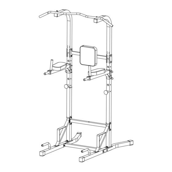
Power Tower
Assembly & User Instructions-Please
Keep for future reference
933/9277
Important
–
Please read these instructions fully before assembly or use
These instructions contain important information which will help you get the best from your
equipment and ensure safe and correct assembly, use and maintenance.
If you need help or have damaged or missing parts, call the Customer Helpline: 0345 6001714
or visit www.argos-support.co.uk
Issue 1 -5/10/17
Advertisement
Table of Contents

Related Manuals for Pro Fitness Power Tower


Summary of Contents for Pro Fitness Power Tower
- Page 1 Power Tower Assembly & User Instructions-Please Keep for future reference 933/9277 Important – Please read these instructions fully before assembly or use These instructions contain important information which will help you get the best from your equipment and ensure safe and correct assembly, use and maintenance.
-
Page 2: Table Of Contents
Contents Safety Information 错误!未定义书签。 Components - Parts 错误!未定义书签。 Components - Fixings 错误!未定义书签。 Assembly Instructions 5-12 错误!未定义书签。 Workout Area Exercise Information 14-19 2-18 错误!未定义书签。 Before starting Muscle Chart 15-16 Calf/Achilles stretch Using the equipment 18-19 Care and Maintenance Exploded Parts Diagram Parts List... -
Page 3: Safety Information
Safety Information Important – Please read fully before assembly or use This exercise equipment is built for optimum safety. However, certain precautions apply whenever you operate a piece of exercise equipment.Be sure to read the entire manual before you assemble,operate or use this equipment. -
Page 4: Components - Parts
Components - Parts If you have damaged or missing parts, please call the Customer Helpline: 0345 6001714 Please check you have all parts listed below Some of the smaller components may be pre-fitted to larger components. Please check carefully Note: before contacting Argos regarding any missing components. -
Page 5: Components - Fixings
Components - Fixings Please check you have all parts listed below The quantities below are the correct amount to complete the assembly. In some cases more hardware Note: may be supplied than are required. Some of the fixings are pre-fitted to the larger components. Please check carefully before contacting Argos regarding any missing fixings. -
Page 6: Assembly Instructions
Assembly instructions Step 1 A. Attached the Cross beam (3) to the Right Stabilizer (2), Align the hole and secure with 2 x M10x70mm Carriage Bolt (16),1XBracket(14#), 2 x Ø10mm Washer (21) and 2 x M10 Aircraft Nut (23). B. Repeat A to secure the other end of the Cross Beam(3) to the left Stabilizer (1). Note: Do not fully tighten the bolts and nuts until getting the instruction. - Page 7 Assembly instructions Step 2 A. Attach one Lower Vertical Frame (6) onto the Left Stabilizer (1) and secure them with 2xM10 Aircraft Nut(23), 2x10mmWasher (21),1xBracket (14) and 2xM10x70mm Carriage Bolt (16). B. Repeat the same way in A to install the other Lower Vertical Frame(6). Note: Do not fully tighten the bolts and nuts until getting the instruction.
- Page 8 Assembly instructions Step 3 Attach one end of the Low Connection Frame(4) to one Lower Vertical Frame(6),Align the hole and secure with 2 x M10x70mm Carriage Bolt (16),1XBracket(14), 2 x Ø10mm Washer (21) and 2 x M10 Aircraft Nut (23). Repeat the above to install the other end of the Low Connection Frame(4) with the other Lower Vertical Frame(6) together.
- Page 9 Assembly instructions Step 4 Attach the Foot Support(5) to the stabilizer(1) and lower vertical frame (6) together, align the hole and secure with 2 x M10x20mm Allen Bolt (17), 2 x Ø10mm Washer (21) . Repeat the same above information to install the other foot support. Note: Do not fully tighten the bolts and nuts until getting the instruction.
- Page 10 Assembly instructions Step 5 Insert the 1X Upper Frame(10) into the Lower Vertical Frame(6) , Attach the Backrest pad support (9) with them together, Align the hole and secure with 2 x M10x70mm Carriage Bolt (16),1X bracket(15), 2 x Ø10mm Washer (21) and 2XM10 Aircraft nut(23). Note: Do not fully tighten the bolts and nuts until getting the instruction.
- Page 11 Assembly instructions Step 6 Repeat the Step 5 to install the other end of the Backrest pad support (9) , Upper Frame(10) Lower Vertical Frame(6) together. Note: Do not fully tighten the bolts and nuts until getting the instruction.
- Page 12 Assembly instructions Step 7 Attach the Chin Up Bar(11) as the diagram shows, Align the hole and secure with 2x M10x90mm Allen Bolt (20),4 x Ø10mm Washer (21) and 2XM10 Aircraft nut(23). Note: Do not fully tighten the bolts and nuts until getting the instruction.
- Page 13 Assembly instructions Step 8 A. Attach the Backrest Pad(33) to the Backrest Pad Support, Align the hole and secure with 2 x M8x40mm Allen Bolt (19),2x Ø8mm Washer (22) . 75mm B. Attach the Left Dip Support(7) to the Lower Vertical Frame and secure it with Lock Pin(31) 70 mm Lock Pin(34).
-
Page 14: Workout Area
Workout Area The free area must be at least 0.6m greater than the training area. This is a space where you can safely dismount, without obstruction, in case of an emergency. Where two pieces of equipment are positioned adjacent to each other the free area may be shared. Only one person should be within the training area when the equipment is in use. -
Page 15: Exercise Information
Exercise Information Before starting Tailor your exercise program according to your physical condition. If you have been inactive for several years, or are overweight, you must start slowly and increase your time on the equipment; a few minutes per workout increase is advisable. Initially, you may be able to exercise only for a few minutes in your target zone, however, your aerobic fitness will improve over the next six to eight weeks. -
Page 16: Muscle Chart
If you are working above your target zone, you may want to do a lower number of reps. Targeted Muscle Groups The exercise routine that is performed on the Power Tower will develop combined total body muscle groups. These muscle groups are highlighted on the power Tower will develop chart below. - Page 17 Exercise Information Warming up and Cooling down Each workout should include the following three parts: 1. A warm-up, consisting of 5 to 10 minutes of stretching and light exercise. A proper warm-up increases your body temperature, heart rate, and circulation in preparation for exercise. 2.
-
Page 18: Calf/Achilles Stretch
Exercise Information Calf/Achilles stretch With one leg in front of the other, reach forward and place your hands against a wall. Keep your back leg straight and your back foot flat on the floor. Bend your front leg, lean forward and move your hips toward the wall. -
Page 19: Using The Equipment
Exercise Information Using the equipment Important: When working out, do the following for each exercise: exhale while exerting/lifting and inhale while returning to starting position in a slow and controlled manner. Read all caution and warning stickers before using this equipment. ... - Page 20 Exercise Information...
-
Page 21: Care And Maintenance
Care and Maintenance 1. The safety level of the Replace defective components Should you have any difficulty equipment only immediately and/or keep the with assembly, operation or maintained if it is examined equipment out of use until use of your exercise product or regularly for damage and wear repair. -
Page 22: Exploded Parts Diagram
Exploded Parts Diagram... -
Page 23: Parts List
Parts List Description Code Description Code Left Stabilizer 2A1204736 M8X60 Allen bolt 3B51DBD00139 Right Stabilizer 2A1204735 M8X40 Allen bolt 3B51DBD00135 Cross Beam 2A1204737 M10X90 Allen bolt 3B51DBD00087 Connection frame 2A1204745 φ10 washer 3B53DIB00002 Foot support 2A1204738 Φ8 washer 3B53DIB00003 Lower Vertical Frame 2A1204739 M10 Aircraft nut 3B52DCC00002... - Page 24 Guarantee Product Guarantee This product is guaranteed against manufacturing defects from a period of Year This product is guaranteed for twelve months from the date of original purchase. Any defect that arises due to faulty materials or workmanship will either be replaced, refunded or repaired free of charge where possible during this period by the dealer from whom you purchased the unit.
Need help?
Do you have a question about the Power Tower and is the answer not in the manual?
Questions and answers