Table of Contents
Advertisement
Advertisement
Table of Contents

Related Manuals for YUNEEC H850


Summary of Contents for YUNEEC H850
- Page 1 H850 Operation Manual...
-
Page 2: Table Of Contents
Product Overview ........3 Re-bind ............25 H850 Drone..........3 Data Pilot APP ........... 28 T1 Transmitter .........4 Main interface overview ....... 28 Charge the Batteries .........5 Video Link Interface ....... 33 Charging the Drone Battery ....5 Mission Flight Mode ......35 Charging Box Screen Overview ....5... -
Page 3: H850 Drone
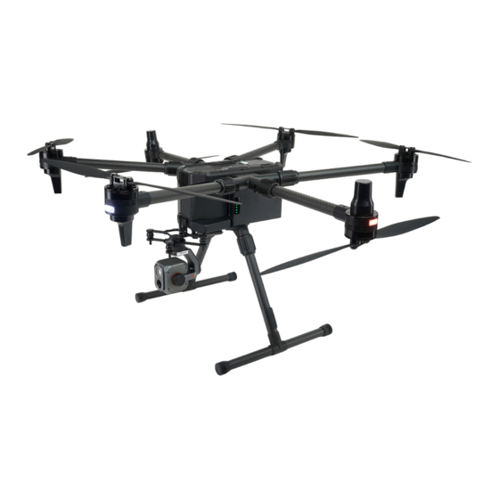
Overview H850 Drone Propeller LED Status Indicator Battery Chamber Landing Gear RTK Antennas OFDM Antennas Debug/Custom Type-C USB Port Gimbal/Custom Type-C USB Port Binding Button and LED Indicator Power Button GMAC Port Type-A USB 3.0 Port Micro SD Slot AUX out Port PWM &... - Page 4 T-1 Transmitter Antennas Previous Button Left Control Stick Customizable Knob Power Button 5D Button Flight Mode Switch Battery Level LEDs Home Page Button Right Control Stick Motor Start/Stop Button Return to Launch Button Type C USB Charging Port Micro SD Card Slot Headphone Port HDMI Port Video Record Button...
-
Page 5: Charge The Batteries
Charging the Batteries Charging the Drone Battery Connect the Charge box to a 100-240V AC outlet. Then press the power button to switch on the charger. Plug the drone or transmitter battery into the charger port as illustrated. The batteries will charge automatically. Charge Box Screen Overview Drone battery charge ports Transmitter battery charge ports... -
Page 6: Assembly
TIPS: Short click the button on the battery to roughly estimate the power level. High Payload Introduction Various payload types can be attached to the H850 drone for different purposes. The following chapter will introduce some typical payloads of choice. -
Page 7: Visible Light Camera
Visible light Camera E90X Yuneec’s E90X camera is a one-inch CMOS sensor to capture high-quality images with 4k 10 bit in-camera colour processing. Images may be captured in JPEG or DNG format, or simultaneous capture of both formats. Video may be recorded in UHD, 2K, or HD resolutions at a variety of frame rates. - Page 8 Digital Zoom function for E90x Yuneec camera E90x is capable of digital zoom. A digital zoom is an ideal tool for many types of inspection, or getting a closer view of objects further than the camera is able to originally see.
-
Page 9: Thermal Imaging Camera
Thermal imaging camera ETx/E10Tx/E10Tvx/E20Tvx These series are an innovative combination of 3-axis gimbals, thermal imaging cameras and lo cameras. While the thermal imaging camera selectively measures the temperature in the image, enabling it to display relative temperature differences, the low-light RGB camera has a 20 times higher sensitivity than the human eye. - Page 10 Zoom function for E30Zx Zoom in Press and hold the Zoom-in button to increase the optical zoom. When increasing to 30X optical zoom, if the Zoom-in button is pressed again, the camera begins to increase digital zoom. The digital zoom can increase to a maximum of 6X..
- Page 11 Get more information on www.yuneec.com. SD CARD SELECTION Yuneec recommends using a SDXC Class 10 UHS-3 micro SD card for recording 4k video. Using the UHS-3 card allows the camera buffer to record to the micro SD card faster, resulting in fewer buffer overruns.
-
Page 12: Pre-Flight Preparation
The quick start guide does not replace the operator manual. Press and hold the Power Button on the T1 to power On/Off Press and hold the Power button on H850 drone to power On/Off Notice: Always Power on the T1 before powering on the UAS. -
Page 13: Calibrating The Compass
Calibrating the Compass In the following situations recalibrating the Compass is suggested for flight safety: 1. Before the first flight, when you take the drone out of the box; 2. When feeling the drone is drifting after a long-distance flight; 3. - Page 14 Step 3: Calibrating Follow the onscreen display and instructions. During Compass calibration, the H850 will need to rotate along the specific axis which is shown by the LED of each Motor Arm, until a tone is heard to change to the next axis. Repeat this procedure for all six positions. A yellow box with a red arrow indicates the rotation axis, which is calibrating.
-
Page 15: Cors Network Binding
CORS Network Binding: The Network CORS and RTK GPS have been disabled by the default setting. The H850 Drone will be positioned and navigated by using single GPS technology. The RTCM Source was disabled by default under the GNSS RTK item. - Page 16 Step 2: Tap the Settings icon, then tap Vehicle. Select the RTK GPS and tick the Enable RTK GPS box, then restart the drone. Step 3: Tap the Settings icon then tap GNSS RTK. Select NTRIP as the RTCM source, then tick Auto Reconnect.
-
Page 17: Environment Requirement
Step 4: Fill the following NTRIP Stream Settings parameters according to your CORS Network. Notice: You must fill out the Required Tagging Form. Step 5: Tap Apply button to finish the connection process. Notice: When connected to the CORS Network has been successful, the Connection Status display will display a green “Connected”. -
Page 18: Take Off
Take OFF Unfold the propellers manually before starting the motors. The drone has 4 different basic flight modes we suggest placing the flight switch in the middle position to use the Angel mode to take off. Optimal Transmission Range The signal between the drone and the T1 Transmitter is most reliable when the antennas are positioned in relation to the drone below. -
Page 19: Take Off Option 1
Take Off - OPTION 1: After the drone we can start the motors by pressing and holding the motor Start stop button on the T-1 Transmitter and release it when the motors start. Slowly raise the left-hand stick to take off (Mode 2 Shown). Take Off - OPTION 2: Tap the Take Off icon and set the takeoff altitude, then slide on the screen to take off. -
Page 20: Angle Mode
Flight Mode Switch Overview position. ANGLE MODE When in Angle Mode and GPS is available, the H850 will respond according to the T-1 Transmitter. SPORT MODE In sport mode, the drone responses are optimised for agility and speed, making it more responsive to joystick movements. -
Page 21: Indoor Flight
Indoor flight When flying the drone without GPS signal, please switch to the indoor flight mode first then start the motors. Step 1: After the drone and transmitter are connected tap the system setting button, then select the Vehicle item, and tap the Indoor Mode button. Step2: Tick the Enable Indoor Flight Step 3: Push the Flight Mode Selection Switch to the Manual Flight Mode, then press and hold the START/STOP button for about 3 seconds to start the motors. -
Page 22: Go To Location Flight
Go to Location flight. After the drone has taken off with GPS Lock the operator can command the drone fly to a specific point on the map by directly tapping the map. Click the “Go to location” then the tapped point will be marked on the map as the “Go here” point. Slide the slider;... -
Page 23: Orbit Flight
Orbit Flight After the drone has taken off with GPS Lock the operator can command the drone to fly to orbit a specific point on the map by tapping the map directly. Tap the “Orbit at location” point then the tapped point will be marked on the map as the orbit centre point. -
Page 24: Roi Flight
ROI Flight After the drone has taken off with GPS Lock the operator , can command the gimbal towards a specific point of interest on the map by directly tapping the map Select the “ROI at location”, then slide to confirm the tapped point will be marked on the map as the ROI point. -
Page 25: Land
Landing Slowly lower the throttle/altitude joystick below the centre position, H850 will descend slowly and land. After the drone lands, the motors will stop after 2 seconds without any operation. Mode 2 Shown Emergency Motor Stop The s operator can force stop the motors by the following operation in the emergency situation such as the blades could hit the people and cause serious injury. -
Page 26: Gimbal Control
The pilot can follow the steps below if rebinding is needed. Step 1: Power on the H850 Drone. Wait a few seconds for all systems to boot up. Step 2: After initialisation completes, use a paperclip or similar item to push the bind button inside the hole as shown the picture. - Page 27 Step 3: Power on the T1 Transmitter and tap the USYNC Button to bind. Step 4: Tap the Next Button to start the binding process.
- Page 28 Step 5: Connecting. Step 6: Tap the “Finish” button to finish the binding process.
-
Page 30: Data Pilot App
Data Pilot APP DataPilot ™ is an economical and efficient task planning software tailored for industry operators, which is preinstalled in the smart transmitter for all the YUNEEC commercial drones. Main Interface Overview Full-Screen Map Interface Main Interface Button Return to the main interface from any other interface by tapping this button. - Page 31 Flight Modes Indicator Display the current Flight Mode of the drone. Obstacle Avoidance Indicator After the Obstacle Avoidance is switched on, this icon will turn green to remind the operator this function is enabled. enabled Note: For the drones without the Obstacle Avoidance function, this indicator will be hidden. Communication status indicator This indicator shows 3 different communication statuses, as in the picture shown below Gray: The drone doesn’t connect to the transmitter.
- Page 32 To close the dialog box, just tap other areas on the screen. Drone GPS indicator This icon displays the Drone GPS status. When the icon turns green it means the drone has an ideal positioning accuracy for flight. Tap this icon to display more information of the drones GPS status. To close the dialog box, just tap other areas on the screen.
- Page 33 The operator can select, refresh, connect or reset the available Wi-Fi hotspot under the Wi-Fi Setting Menu. Refresh the Wi-Fi hotspots Connected Wi-Fi hotspot Available Wi-Fi hotspots Close the Wi-Fi Setting Menu Available Wi-Fi hotspots The operator can select the Wi-Fi hotspot wanted by tapping the SSID in the available Wi-Fi hotspot list, and then enter the passwords to connect.
- Page 34 The operator can tap the hide icon to hide the thumbnail window, or drag the icon to adjust the size of the window. Tap and drag to adjust the size of the thumbnail window Tap to hide the thumbnail window Flight Data Panel Indicate the flight data Compass and Course...
-
Page 35: Video Link Interface
Video Link Interface After The Main Screen has been switched to the Video Link feedback interface, the operator will get the screen shown below: 1Camera quick access menu The operator can adjust the camera parameter quickly by using this menu. Such as exposure mode, white balance, etc. - Page 36 Photo/Video Mode Switch Switch the Camera mode between the Photo mode with the Video recording mode. Just tap the Icon to switch the Camera work mode. Camera in video mode Camera in Photo mode Shutter/Record button In the Video Recording mode the icon is a red dot. Tap it to start recording the video and tap again to stop recording.
-
Page 37: Mission Flight Mode
Camera Setting Button Tap this button to open the camera menu for further settings. Note: According to different camera types the camera setting menu change. Please refer to the corresponding chapter of the gimbal manual for the camera setting menu instruction in detail. - Page 38 Add Waypoints If the operator needs to plan a fight mission in a new area, connect the transmitter to the internet via a Wi-Fi hotspot to download maps After entered the Mission planning mode, select a Blank plan and tap the Takeoff icon on the left side of the screen.
- Page 39 Selected Waypoint Parameters Display the parameters of the selected waypoint. Mission Summary Display the Summary of the entire flight mission added to this map. Selected Waypoint When a waypoint was selected, it will be marked colour in “Green” Ahead Direction Indicator This white arrow shows the forward direction of the drone along the flight route.
-
Page 40: Adjust The Waypoint Parameters
Other Waypoints Take Off Point Selected Waypoint Waypoint number Mission Start Point Terrain Altitude 9Waypoint Setting Panel This panel isthe setting panel for each waypoint to adjust the waypoint parameters in detail. Adjusting the waypoint parameters Once a waypoint was set and selected, the screen will pop up the ‘Way point Setting Panel’ on the right side. - Page 41 Camera Behavior Setting Menu Tap to open the Drop-down menu for Camera behavior setting for the selected waypoint. Camera Mode Setting Menu Tick the Box before the “Mode” then tap to open the Drop-down menu for Camera mode setting for the selected waypoint.
-
Page 42: Pattern
When the drone was positioned by GPS and Connected with the Transmitter. The operator can tap the “Move to vehicle position” to make the waypoint coinside with the drone. Tap the “Move to previous item position” to make the selected waypoint coincide with the previous one. -
Page 43: Survey Mode
Survey Mode Survey mode allows the Pilot to quickly place a survey grid over a desired area. To select a survey grid mission, tap the Survey button after tapping the Mission Route Setting icon. Then tap the Survey button on the right side of the screen to finish the further settings. There are 3 preset templates to choose from for editing the survey area. - Page 44 Basic preset template overview Tap the “Basic” button, the App will generate a rectangle survey area. Tap and hold the Centre dot to drag the survey area on the map. Tap and hold the white vertices then drag them to adjust the shape of the survey area.
-
Page 45: Adjust The Survey Parameters
with Polygon” button and then tap the “Done Adjusting” button for the further settings. Notice: For the Trace template, please tap the “Done Tracing” First, and then tap the “Done with Polygon” and other buttons. Adjust the Survey parameters After the Survey area has been confirmed the operator can adjust the survey parameters. Click the “Grid”... - Page 46 Overlap Front Overlap – Creates images with a percentage of each image overlapping to the front of the image. Side Overlap – Creates images with a percentage of each image overlapping to the side of the image. Red Arrow: Flight Route Front Lap for 2 Side Lap for 2 photos...
- Page 47 Angle Angle –Drag the slider or type in the parameter to adjust the angle of the survey grid lines. Turnaround dist – Sets the distance outside the survey for the drone to turnaround. Type in the parameters directly to adjust the distance Rotate Entry Point Button -The DataPilot App will offer more than one solution to lead the drone enter and exit the survey area, the operator can change the enter and exit point by tapping the “Rotate Entry...
- Page 48 The Operator can also tap the ‘+’ dot on the enter flight route for editing a more complex entering flight route. New Enter Route Options Taps the Options to open the Drop-down menu Hover and capture image – After this Item is ticked the drone will stop and hover and then capture the image at each capture point for better image quality.
- Page 49 Capturing images continuously while flying on the turnaround route. Terrain Tap the Terrain button and tick the Vehicle follows terrain to make the drone fly closer to the ground for capturing more pictures or fill the holes in the following inner process work flow.
- Page 50 Save reload and delete the survey data Tap the Presets button to save the setting parameters under the Grid and Camera Items. Tap the “Save Settings As New Preset” button to create a new save. Type the name and tap the “Save” button to finish.
-
Page 51: Corridor Scans
After the file name was selected tap the “Apply Preset” button to load the parameters. Tap the “Delete Preset” button to delete the useless preset files. Tap the trash can icon beside the Survey to delete the whole survey mission. CORRIDOR SCANS Roadways, power lines, train tracks, footpaths, and other narrow winding areas may be set up as “corridor scans.”... - Page 52 To create the CORRIDOR SCAN, tap the Corridor Scan button after tapping the Mission Route Setting icon. If the transmitter is already connected to the drone and the drone GPS position was established, the takeoff point will be set above the drone location, otherwise place the takeoff point at the position you need then tap the “Done Adjusting”...
- Page 53 Basic preset template overview Next tap the “Basic” button, the App will generate a corridor scan area with 2 vertices. Tap and hold the vertices dot to drag the corridor scan area on the map. Tap ‘+’ dot allows additional vertices to be created/inserted in the pathway, allowing for numerous angles to follow the road.
- Page 54 side. Through this panel the operator can set all the CORRIDOR SCAN parameters. Drag the panel up and down to view more items. Adjust the Corridor Scan parameters After the Corridor Scan area has been confirmed the operator can adjust the scan parameters. Click the “Grid”...
-
Page 55: Structure Scans
A Structure Scan allows s the operator to STRUCTURE SCANS create a grid Flight pattern that captures images over vertical surfaces (e.g. walls) around a structure with an arbitrary polygonal (or circular) ground footprint. Structure Scans may be combined with nadir/survey flights to better serve architects, engineers, and construction companies looking to create accurate 3D models, or output .las files to... - Page 56 Basic preset template overview A green overlay will appear with four corners. Tap and hold the Centre dot to drag the survey area on the map. Tap and hold the white vertices then drag them to adjust the shape of the structure scan area. Tap ‘+’...
- Page 57 A green overlay will appear with four corners. The region shown in green must be modified so that it surrounds the structure. • Drag the opaque vertices on the map to the edge of the structure. • If the structure footprint is more than a simple square, click the semi-transparent circles between the vertices to create a new vertex.
-
Page 58: Other Functions Of The Plan Panel
Other functions of the Plan Panel After entering into the Mission planning mode by tapping the Mission Route Setting icon, the File button will be activated automatically. Beside the Waypoint other Pattern missions can be created by tapping directly on the pop up create plan window, the operator can also save the created flight plan or open an existing plan Select a flight plan type to create. -
Page 59: Execute The Flight Mission
After the drone and transmitter are connected the Coaching button will be displayed on the plan setting panel. The coaching function will allow the Datapilot 2.0 App to capture the drone current GPS position as a new waypoint. Tap the takeoff button to add a takeoff point for the Blank flight plan, and then tap the Coaching button, the operator can add a waypoint by a long press on the waypoint button. -
Page 60: Operations In Mission Flight Mode
Tap the Main Interface Button to switch back from the Mission planning interface. Slide the slider to confirm and the drone will execute the flight mission automatically. Operations in mission flight mode Pause the flight mission The s operator can pause the flight mission by the following 3 method: 1. - Page 61 Continue the flight mission 1. Slide the slider to continue the mission. 2. Tap the Action button then select continue or set the new altitude. Tap the “Continue Mission” Set the new altitude then button then slide to confirm slide to confirm. to continue the mission.
-
Page 62: Breakpoint Continuation
Land or Return in mission flight Tap the Land button and slide to confirm then the drone lands at the current position. Tap the Return button and slide to confirm then the drone returns to the launch point. Breakpoint continuation Sometimes surveying a huge area, the drone can’t finish the job in 1 flight. -
Page 63: Setting Interface
Due to the DataPilot 2.0 App is a cross platform flight control application, beside the H850, there are many items in the setting interface that are designed for other types of drone such as H520E and Q820, please ignore the items which are not featured in this manual. They may be not compatible or the H850 drone doesn’t have this function. - Page 64 Miscellaneous Language- s Operator can make selections according to their own requirements in the drop-down menu. Colour Scheme-The DataPilot 2.0 supports 2 different colour schemes. Indoor scheme will provide a dark interface meanwhile the outdoor has a bright interface. Indoor Outdoor Map Provider and Map Type-The operator can change the map provider and type according to their network speed or requirements.
-
Page 65: Offline Maps
Other settings in General Items-We suggest keeping them as the default setting. 2. Offline Maps The Offline Maps allows the Datapilot 2.0 App store the map tile in the cache in the transmitter for working in the field without the internet. After the transmitter is connected with the internet the map will be downloaded automatically according to the drone or the transmitter GPS position. - Page 66 New set edit interface Introduction Map centre setting button New Tile Set Name Edit Box The operator can tap this button and The operator can edit the name of the select the centre position on the sub new tile set in this box. menu.
- Page 67 Similar to the Default Tile Set, the new added tile set can be reviewed by tapping the name and can be deleted by tapping the Delete button. The difference is the new added tile set can be renamed and the “OK” button tapped to confirm. Downloaded area Name edit box The downloaded map tile set can be imported and exported between devices.
-
Page 68: Version
Import After tapping the Import button, select an import method then tap the Import button on the popped up dialog box and select the file to import. Export After tapping the Import button on the Offline Maps main interface, tick the tile set wanted and tap the Export button then assign the name and save path on the popped up dialog box, finally tap the Ok button to export. -
Page 69: Gnss Rtk
Once the later version was detected, the update process can be started. 4. GNSS RTK In the sub menu under the GNSS RTK item the operator can enter to parameters to connect the drone system to the CORS source. Please refer to the corresponding chapter in the quick start Guide and this operator manual mentioned above. - Page 70 Follow the guidelines of the transmitter to move all the joysticks and knobs to their limits. The joysticks and knobs which passed the Calibration will be marked green. After all of them have passed release your hands from the joysticks and knobs to keep them at the centre position, then tap the Stop Calibration button.
-
Page 71: Vehicle
Tap OK button to finish the calibration 6. Vehicle The roperator can reset parameters, control the motor LEDs, enable the indoor mode, enable the RTK GPS and check the vehicle info under this item. Reset parameter button... - Page 72 Tap the “Reset Parameters” button first then tap the “Reset” button. Tap the “Reboot Now” button to reboot drone then the reset will take effect. LED Control In the cases of taking the aerial photography at night the motor LEDs can influence the colour effect of the photos.
- Page 73 Tap the white arrow to open the drop-down menu then select the needed LED setting, the LEDs On is the default setting. LEDs Off - Switch off all the motor LEDs. LEDs On - Switch on all the motor LEDs. Front LEDs Off –...
- Page 74 7. Summary This item displays the summary of the settings for the vehicle. 8. RC Mode Tap to select the Joystick mode you wish to use.
-
Page 75: Sensors
This 2 item section allows the operator to edit the drone behavior after the RC or Data Link Loss. For the H850 drone please retain the “Disable” selection for the Data Link Loss Failsafe Trigger. Only editing the RC Loss Failsafe Trigger is enough. - Page 76 Tap the white arrow to open the drop-down menu then select a Failsafe behavior. Disabled- The drone will maintain the last flight mode before the RC Loss. Hold mode- The drone will keep hovering after the RC Loss. Return mode-The drone will trigger the RTL mode after RC Loss. Land mode-The drone will land directly at its current position after RC Loss.
- Page 77 Tap the white arrow to open the drop-down menu then select an Action on breach. None - Although the Max Radius and Max Altitude are already set the “None” selection will still deactivate the geo fence andthe drone will not react after it reaches the edge of the geo fence. Warning- The transmitter will trigger the continuous warnings when the drone reaches or flies out of the geo fence.
- Page 78 Return Home Settings Climb to altitude of- Tap the box then type in the altitude to set a new altitude. The 20m is the default setting. When the drone is below the altitude set after the operator enables the RTL mode the drone will climb to the RTL altitude first then flying back to the return point.
-
Page 79: Attachment
Max Vertical and Horizontal Velocity setting Tap the box for each items then type in the parameters to set the max climb, descent and horizontal velocity. Notice: We do not suggest the operator to change these parameters for flight safety. Attachment Specification T1 Transmitter... - Page 80 Max Flight Time 60min (Without payload) The propeller diameter 440mm The Motor Type BL5008 The Motor KV Value Battery LiHv 6s 12800mAh Charger H850 Charge Box Recharge Time 1.5 hours Position System GPS+GLONASS +BeiDou+Galileo Hovering Accuracy(Single) Horizon:±0.5m Vertical:±0.5m RTK(RMS) Accuracy 1cm +1ppm(H);...
- Page 81 Disclaimer...
- Page 82 Yuneec International (China) Co., Ltd shall not be held liable for any damage, injury or for use of the product in violation of legal regulations, especially in the following circumstances: Damage and/or injury as well violation of legal regulations resulting from a failure to comply with the operating instructions or the instructions at www.yuneec.com, product information, operator...
- Page 83 Damage and/or injury as well as violation of legal regulations caused by flying in legally defined no-fly zones. Further losses which do not fall within the scope of use are defined by Yuneec as improper. This product is designed for both professional use and personal private use. The national and international laws and regulations in force at the time of taking off must be adhered to.
- Page 84 You must always charge the Li-ion battery in a safe, well-ventilated area away from flammable materials. Never charge the Li-ion battery unattended at any time. When charging the battery, you must always remain in constant observation to monitor the charging process and react immediately to any potential problems that may occur.
- Page 85 Keep your hands, face and other parts of your body away from the spinning propellers/rotor blades and other moving parts at all times. Keep items that could impact or become entangled away from the propellers/rotor blades including debris, parts, tools, loose clothing, etc. Always operate your aircraft in open areas that are free from people, vehicles and other obstructions.
- Page 86 FCC Statement This equipment has been tested and found to comply with the limits for Part 15 of the FCC rules. These limits are designed to provide reasonable protection against harmful interference in a residential installation. This equipment generates, uses and can radiate radio frequency energy and, if not installed and used in accordance with the instructions, may cause harmful interference to radio communications.
- Page 87 5G: 5725-5850MHz (12dBm). EU COMPLIANCE STATEMENT Hereby, Yuneec International (China) Co., Ltd. declares that this device is in compliance with the essential requirements and other relevant provisions of the RED Directive 2014/53/EU. The full text of the EU Declaration of Conformity is available at the following internet address:...
- Page 88 H850 Yuneec Support www.yuneec.com This content is subject to change downloads the latest version from www.yuneec.com If you have any questions about this document, please contact us by starting a conversation on www.yuneec.com...
Need help?
Do you have a question about the H850 and is the answer not in the manual?
Questions and answers