
Related Manuals for ABB OMD100


Summary of Contents for ABB OMD100
- Page 1 — I N S TA L L AT I O N A N D O P E R AT I N G I N S T R U C T I O N Automatic control unit OMD100...
-
Page 2: Table Of Contents
3.1.2 No line priority 3.1.3 Manual back switching 4. Installation Dimensional drawings Mounting 4.2.1 Automatic control unit OMD100, door mounting 4.2.2 Automatic control unit OMD100, DIN-rail mounting 5. Connecting Power circuit Control circuit 5.2.1 Control circuit diagram OMD100 with motorized OTM40...125_CMA_... - Page 3 7.2.1 Rotary switches 7.2.2 DIP switches / parameter setting 31 – 32 TEST sequence 8. Technical data of the automatic control unit OMD100 9. Troubleshooting OMD100 Explanations of internal faults, OMD100 Change-over switch does not respond 36 – 37 10. Accessories 10.1...
-
Page 4: Introduction
A U T O M AT I C C O N T R O L U N I T, O M D 1 0 0 — 1. Introduction This manual describes the installation and the basic operation of the OMD100 automatic control unit. The instructive part is followed by a section on available accessories. —... -
Page 5: Product Overview
OMD100 is the basic version of the control unit of automatic switching equipment. It has two sensors to monitor two three-phase power lines, both able to work with single phase, too. OMD100 can measure voltage, frequency and the phase balance of the primary and secondary power line. -
Page 6: Typical Applications
— 2.1 Typical applications Network line a – Network line b In case of loss of the primary power line, the OMD100 device manages the switching to a secondary power line used as an emergency source. Figure 2.2 Network line a - Network line b Automatic control unit type OMD100 is designed for single and three-phase distribution systems in diverse applications. -
Page 7: Description
A U TO M AT I C C O N T R O L U N I T, O M D 1 0 0 — 3. Description — 3.1 OMD100 switching sequence 3.1.1 Line 1 priority The switching sequence can be summarized in following steps: An anomaly occurs on the Line 1... -
Page 8: No Line Priority
A U T O M AT I C C O N T R O L U N I T, O M D 1 0 0 3.1.2 No line priority The switching sequence can be summarized in following steps: An anomaly occurs on the Line 1 Switching delay Change-over switch (Switch I) to the position O Change-over switch (Switch II) to the position II... -
Page 9: Manual Back Switching
A U TO M AT I C C O N T R O L U N I T, O M D 1 0 0 3.1.3 Manual back switching The switching sequence can be summarized in following steps: An anomaly occurs on the Line 1 Switching delay Change-over switch (Switch I) to the position O Change-over switch (Switch II) to the position II... -
Page 10: Installation
A U T O M AT I C C O N T R O L U N I T, O M D 1 0 0 — 4. Installation — 4.1 Dimensional drawings Figure 4.1 OMD100, dimensions of the device... -
Page 11: Mounting
A U TO M AT I C C O N T R O L U N I T, O M D 1 0 0 — 4.2 Mounting 4.2.1 Automatic control unit OMD100, door mounting The automatic control unit OMD100 can be mounted on the door with the fastener OMZD1, see Accessories, Section 10. Door drilling according to Figure 4.2. OMZD1 ×2 Figure 4.2... -
Page 12: Automatic Control Unit Omd100, Din-Rail Mounting
A U T O M AT I C C O N T R O L U N I T, O M D 1 0 0 4.2.2 Automatic control unit OMD100, DIN-rail mounting The automatic control unit OMD100 can be mounted on the 35 mm DIN-rail and the door drilling, if needed, according to Figure 4.3. -
Page 13: Connecting
A U TO M AT I C C O N T R O L U N I T, O M D 1 0 0 — 5. Connecting — 5.1 Power circuit Operating voltage: Main voltage: 380 Vac ( 20 %) ±... -
Page 14: Control Circuit
Control circuit diagram OMD100 with motorized OTM40...125_CMA_ L1 L2 L3 N L1 L2 L3 N OMD100 Signaling OK/Equipment Alarm Alarm Equipment earth Equipment earth from DIN-rail Supply Motorized OTM40-125F_CMA Figure 5.1 Control circuit diagram OMD100 with motorized OTM40…125_CMA_ Equipment earth must always be connected. -
Page 15: Control Circuit Diagram Omd100 With Motorized Otm160
Control circuit diagram OMD100 with motorized OTM160...2500_CM_ L1 L2 L3 N L1 L2 L3 N OMD100 Signaling OK/Equipment Alarm Alarm Equipment earth Equipment earth from DIN-rail Supply Motorized OTM160-2500_CM Figure 5.2 Control circuit diagram OMD100 with motorized OTM160…2500_CM_ Equipment earth must always be connected. -
Page 16: Connectors, Omd100
Output to signal Alarm X31:1 Manual / Alarm input from handle X31:2 Status of switch I auxiliary contact X31:3 Status of switch II auxiliary contact X31:4 Voltage supply from the automatic control unit OMD100 Equipment earth Table 5.1 Connectors OMD 100... -
Page 17: Omd100 Outputs
5.2.5.2 Force manual, X31:1 (DI3) When the handle is attached this input is closed and OMD100 is forced to Manual Mode. To set the OMD100 back to the Automatic Mode the handle must be removed and the AUTO key pushed (Auto... -
Page 18: Operating
— 6.1 Automatic control unit in Manual Mode Selecting the automatic control unit OMD100 to the Manual Mode: a. Make sure that the power LED is ON, see the Figure 6.1/ . b. If the Auto LED is OFF / , the automatic control unit is in Manual Mode. - Page 19 A U TO M AT I C C O N T R O L U N I T, O M D 1 0 0 To select the switch to operate by the automatic control unit OMD100 in Manual Mode: a. Push the appropriate I, O or II key.
-
Page 20: Automatic Control Unit In Automatic Mode
— 6.2 Automatic control unit in Automatic Mode Selecting the automatic control unit OMD100 to the Automatic Mode: Make sure that power LED is ON. If Auto LED is ON/ , the automatic control unit is in Automatic Mode. If Auto LED is OFF/ , check that the Lim rotary switch is not in the TEST or SETUP position/ . -
Page 21: Selection Of Delay Time, Voltage Threshold And Test Function
Lim = Voltage threshold with SETUP and TEST function The available selections for voltage threshold in OMD100 are: ± 5, ± 10, ± 15, ± 20 %. By setting the voltage threshold, the unbalance is also set to the same level. - Page 22 MANUAL mode. By pushing AUTO key once after stopping test sequence the device is set to the AUTO mode. Tbs=300s SETUP TEST Tbs=Ts Figure 6.6 Lim rotary switch is set to the TEST function in OMD100...
-
Page 23: Operating Modes
A U TO M AT I C C O N T R O L U N I T, O M D 1 0 0 — 6.4 Operating modes 6.4.1 Operating modes in OMD100 6.4.1.1 Normal switching sequence + automatic OTM_C_D or motorized OTM40…125_CMA_ This operating mode is used when user has automatic OTM_C_D change-over switch or motorized OTM40…125_CMA_ and line priority is Line 1 –... -
Page 24: Choice Of Operating Mode In Omd100
TEST Tbs=Ts Figure 6.8 Setting of SETUP mode with Lim rotary switch in automatic control unit OMD100 Press AUTO button to choose the mode. The Operation modes are indicated by LEDs according the Table 6.1, see next page. Figure 6.9 Choosing the Operation mode by pressing the AUTO button. - Page 25 Manual back switching mode + motorized OTM160…2500_CM_ + motorized OTM160…2500_CM_ OTM160…2500_CM_ Table 6.1 Indications of the Operating modes in automatic control unit OMD100 Set Lim rotary switch back to original position Tbs=300s SETUP TEST Tbs=Ts Figure 6.10 Setting of SETUP mode with Lim rotary switch in automatic control unit OMD 100...
- Page 26 A U T O M AT I C C O N T R O L U N I T, O M D 1 0 0 Set device to AUTO mode according to the Figure 6.11. Tbs=300s Automatic mode Tbs=300s SETUP SETUP TEST TEST Tbs=Ts Tbs=Ts Automatic mode O F F Figure 6.11 Selecting the automatic control unit OMD100 to Automatic Mode...
-
Page 27: Using Automatic Control Unit Omd100
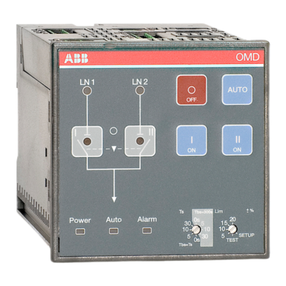
Figure 7.2 Keypad on OMD100 AUTO key Selecting the automatic control unit OMD100 to the manual or automatic mode. An active alarm can reset by the AUTO key. O key Setting the motorized change-over switch OTM_C to the OFF position in manual and auto mode;... -
Page 28: Leds
LN 2 Auto Alarm Power Figure 7.3 LEDs on OMD100 Line 1 status (LN1) A red LN 1 LED signals the status of the line LN 1. Line status and indication is explained in the Table 7.1. Line 2 status (LN2) A red LN 2 LED signals the status of the line LN 2. - Page 29 An active alarm is set off by pushing the AUTO key. Auto A green Auto LED signals the automatic or the manual mode. When the OMD100 is in automatic mode, the Auto LED is ON. When the device is in manual mode, the Auto LED is OFF. In test sequence the Auto LED is blinking.
-
Page 30: Configuration
Section 6.4.2 Choice of Operating mode in OMD100. When the Lim rotary switch is set to the TEST position, the automatic control unit OMD100 enters the test sequence. In test sequence it is possible to simulate switching and back switching... -
Page 31: Dip Switches / Parameter Setting
Do not attempt any installation or maintenance actions when an automatic transfer switch is connected to the electrical mains. Before starting work, make sure that the switch is de-energised. The parameter setting of automatic control unit OMD100 is performed by the DIP switch. The DIP OMD200 OMD300 switch is situated on the bottom of the OMD100 unit, see Figure 7.5. - Page 32 A U T O M AT I C C O N T R O L U N I T, O M D 1 0 0 7.2.2.1 Parameter settings by DIP switches S23 Figure 7.6 DIP switches in OMD100, the positions are factory default settings DIP switch S23-1 to set phase system S23-1...
-
Page 33: Test Sequence
Lim rotary switch is set to the TEST position When the Lim rotary switch is set to the TEST position, automatic control unit OMD100 enters the test sequence. While entering the test sequence OMD100 blinks all LEDs twice to give the information that the LEDs are functioning. -
Page 34: Technical Data Of The Automatic Control Unit Omd100
IP40 for the front panel Temperature area – 20 to + 60 °C Transportation and storage temperature – 40 to + 90 °C Humidity with condensation 5 % - 98 % without condensation 5 % - 90 % Table 8.1 Technical data of OMD100... -
Page 35: Troubleshooting
Motor/Manual selector of the change- over switch (only with motorized change-over switches OTM160...2500_ CM) is in Motor (M) position and check the fuse (F1) of the motor operator. Table 9.1 Fault situations in OMD100... -
Page 36: Explanations Of Internal Faults, Omd100
A U T O M AT I C C O N T R O L U N I T, O M D 1 0 0 — 9.2 Explanations of internal faults, OMD100 When digital Input 1 and 2 are both active, logic is locked and the Alarm LED is ON. -
Page 37: Change-Over Switch Does Not Respond
9.3 Change-over switch does not respond During the switching sequence, the OMD100 operates the change-over switch (Switch I) first to the position O from position I. If this transition is not completed in three seconds, the Open 1 Failure is activated. -
Page 38: Accessories
A U T O M AT I C C O N T R O L U N I T, O M D 1 0 0 — 10. Accessories — 10.1 Fastener OMZD1 ×2 Figure 10.1 Fastener OMZD1, used when the automatic control unit OMD100 is mounted on the door. - Page 39 A U TO M AT I C C O N T R O L U N I T, O M D 1 0 0...
- Page 40 — Contact us ABB Oy P.O. Box 622 FI-65101 Vaasa Finland abb.com/lowvoltage © Copyright 2023 ABB. All rights reserved. Specifications subject to change without notice.